Gesture Controlled Mobile Robotic Arm
Using Accelerometer
Vivek Bhojak1, Girish Kumar Solanki2, Sonu Daultani3
Assistant Professor, Department of Electronics and Communication, Anand International College of Engineering,
Jaipur, Rajasthan, India1
U.G Student, Department of Electronics and Communication, Anand International College of Engineering, Jaipur,
Rajasthan, India2
U.G Student, Department of Electronics and Communication, Anand International College of Engineering, Jaipur,
Rajasthan, India3
ABSTRACT:In this paper we have presented a model to control robotic arm through human gestures using accelerometer. A three axis accelerometer is mounted on human hand in order to perform the action of robotic arm according to the action of human hand. Accelerometer is connected to the Atmega 16 Microcontroller which is programmed to take analog readings from accelerometer and transmit them using RF transmitter to the receiving unit at robotic arm. Movements of the robotic arm are achieved through Servo-Motor are a type of electromechanical actuators that do not rotate continuously like DC/AC or stepper motors; rather, they are used to position and hold some object. They are used where continuous rotation is not required so they are not used to drive wheels (unless a servo is modified). The arm is also equipped with a gripper to facilitate the pick and drop facility.The whole arrangement is placed on a mobile platform with wheels to facilitate movement from one place to another which can be controlled using a wireless remote control. The main aim is to control the robotic arm using human gestures wirelessly with smooth movement over a range.
KEYWORDS:ADC, MCU, PWM, Gesture, Accelerometer, Servo motor, AVR, Gripper
I. INTRODUCTION
Nowadays, robots are increasingly being integrated into working tasks to replace humans especially to perform the repetitive task. In general, robotics can be divided into two areas, industrial and service robotics these robots are currently used in many fields of applications including office, military tasks, hospital operations, dangerous environment and agriculture. Besides, it might be difficult or dangerous for humans to do some specific tasks like picking up explosive chemicals, defusing bombs or in worst case scenario to pick and place the bomb somewhere for
containment and for repeated pick and place action in industries. Therefore a robot can replace human to do work [1].
There are certain techniques being implemented to control the movement of a robotic arms like Motion sensors &
markers [2], vision systems [3] etc. Use of accelerometer as a gesture recognition device is becoming quite popular due to
its small size and low moderate cost.
of a human arm. Robotic arm whose objective is to imitate the movements of a human arm using accelerometers as sensors for the data acquisition of the natural arm movements. This method of control allows greater flexibility in controlling the robotic arm rather than using a controller where each actuator is controlled separately. The processing unit takes care of each actuator’s control signal according to the inputs from accelerometer, in order to replicate the
movements of the human arm [1].
II. RELATEDWORK
Gesture control is becoming a popular technique in many applications and various works has been implemented in this field. Industrial arms like MOTOMAN HP6 based on learning and Artificial Neural Networks is current related work on this technology [4].
Some researchers [5] used Kinect atHumanitarian Technology (HuT) Labs of Amritathat involves the building of a
Robotic arm which mimics the motion of the human arm of the user. The system monitors the motion of the user's arm using a Kinect. The skeletal image of the arm obtained using the “Kinect Skeletal Image” project of Kinect SDK, consists of 3 joints and links connecting them. Coordinate Geometry is used to calculate the angles between the links connecting the joints. This gives us the angles for a 3D representation of the human arm.
Also, some researchers implemented a Gesture Actuated Robotic Arm [6] using MEMS- accelerometer sensors placed
on different joints of human hand.
Researchers also worked on an Integrated Vision-based robotic arm interface for operators with upper limb mobility
impairments[7] which was developed to operate a commercial wheelchair-mounted robotic manipulator (WMRM)
III.PROPOSED MODEL
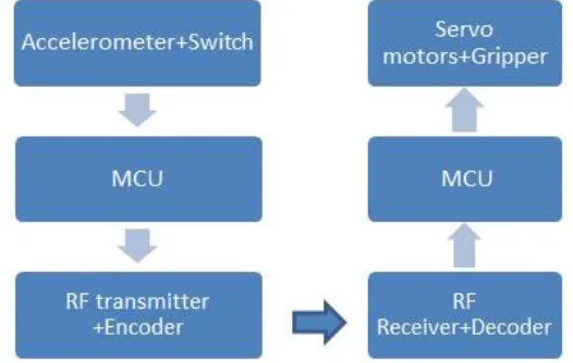
The model consists of the transmitting and receiving units. The system can be understood with the help of flow chart as shown in figure-1.The transmitting unit, as shown in figure- 2 is at human end can be mounted on a glove which is worn by human hand. The unit contains an accelerometer, a microcontroller (ATmega16) for processing the signals and analog values from accelerometer and a RF transmitter to transmit codes against different ADC values from MCU.
Figure 1: Flow Chart of Process
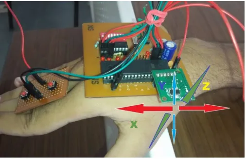
Figure 2: Transmitting End
A. DATA ACQUISITION WITH ACCELEROMETER.
3-axis wireless accelerometer mounted on aglove is used to capture human hand behaviors, and amicrocontroller acquired the values in analog form. The 3-axis accelerometers (ADXL330, Analog Device) is physically rated to measure accelerations over a range of at least +/- 3g, with a sensitivity of 300 mV/g and sensitivity accuracy of 10%. The analog readings from accelerometer can be displayed on a LCD and analyzed to create a mathematical
relation with the PWM control of motors.The advantage ofthe accelerometer
is
that the values do not changeunless there is a change inposition. But theproblem with the accelerometer
is
that itcontained high level ofnoise which makes the values inaccurate. So, to make these values accurate Gyroscopesensor can beused. Figure 3 shows the data acquisition from accelerometer and transmission from human hand.Figure 3: Accelerometer returns X, Y, Z acceleration in sensor’s frame of reference
B. COMMUNICATION
Here we used RKI-1064 Rx-Tx pair based on amplitude shift keying. The operational frequency is 433 MHZ & transmission occurs at a rate of 1Kbps - 10Kbps. Codes corresponding to different sets of ADC values are transmitted and checked at receiving end. If the code received is correct than corresponding PWM value is used to drive the motor at specified angle.
The communication between the transmitting and receiving end is done using RF transmitter-receiver pairs.
C. PWM CONTROLOF SERVO MOTORS.
AVR Timer1 Module which is a 16bit timer and has two PWM channels (A and B). The CPU frequency is 8 MHz this frequency is the maximum frequency that most AVRs are capable of running. And so it is used in
mostdevelopment board like Low Cost AVR Development Boards [8]
TOP Value = ICR1
ICR1=19999; ICR1(Top value)
Period
Figure: 4.AVR MCU TIMER count sequence
So the timer will count from 0 to ICR1 (TOP Value) as shown in figure 4. Registers of MCU are set as: TCCR1A |=1<<WGM11 | 1<<COM1A1 | 1<<COM1A0;
TCCR1B |= 1<<WGM12 | 1<<WGM13 | 1<<CS10;
Here top value is ICR1 which is 19999 so number of cycles will be 20000 each cycle of 20 millisecond and 50 cycles in one second.
The default frequency of MCU we used is 1MHZ, i.e. it corresponds to 1 second. The servo needs a pulse every 20msec. which corresponds to 50Hz. Therefore, no. of cycles we get by dividing 1MHZ.
Cycles= 100000/50 Cycles=20,000 (1)
Hence, range of ICR1=0-19999 And, top value of ICR1=19999
D. Controlling of servo against the analog values from accelerometer.
By taking various observations and relating the analog values from accelerometer with PWM values for motor, following relation is obtained.
P=b*6 (2) OCR1A=ICR1-P (3) Here, b is the accelerometer reading.
P is PWM value
However, an alternative can be used by manually taking readings over a wide range of angles, and defining those values in program.Different codes corresponding to different readings are transmitted and corresponding (Table 1) PWM value (p)for the angle is chosen to move servo. Figure 5 shows the circuitry used to drive servo motor wirelessly.
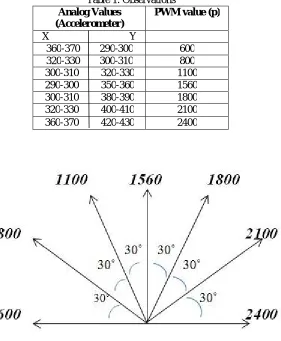
The PWM Values and angle corresponding to different ADC values from accelerometer is shown below in the observation Table 1 and figure 6.
Table 1: Observations
Analog Values (Accelerometer)
PWM value (p)
X Y
360-370 290-300 600
320-330 300-310 800
300-310 320-330 1100
290-300 350-360 1560
300-310 380-390 1800
320-330 400-410 2100
360-370 420-430 2400
Figure 6: Angle Separation Corresponding to PWM Values.
E. Robotic arm and Mobile Platform.
The arm consists of 2 servo motors which provide two degree of freedom to the arm. The servos are attached to the body of arm made of wooden plank and controlling circuitry is placed on a common base. One servo is used for the horizontal motion with angles from -180 to +180 degrees and other servo is for the wrist movement from -90 to +90 degrees. The gripper attached in front is controlled using the push button switch assembly on the glove.The whole arrangement is placed on a mobile platform with wheels for the movement from one place to another controlled using a wireless remote control.
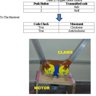
F. Gripper Control.
transmitted on pressing each button & clockwise- anticlockwise movement is decided at receiving end after matching transmitted code.
Table 2: Gripper motor control
Push Button Transmitted code
1 0xfe
2 0xdf
To The Receiver
Code Check Movement
True Clockwise
True Anticlockwise
Figure 4: Gripper Mechanism
IV.APPLICATIONS
1. Scientific:
Gesture control mobile robotic arm can help the scientist performing hazardous experiment in safer way by using robotic arm to pick the Dangerous liquids. This can also help scientist to perform the liquids which are highly flammable.
2. Military:
Gesture controlled robotic arm can also be used for military purpose to perform operation on explosives as gesture controlled robotic arm can also help the bomb squad to detonate or defuse the bomb without involving risk to their life.
3. Space:
V. RESULT
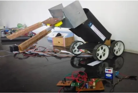
This control mechanism provides an easy movement& control of arm but doesn’t facilitate the teaching and learning. Thus, a cheap and easy way of control using popular AVR microcontrollers and RF devices is implemented. The structure of arm and mobile platform as shown in figure 8, works efficiently replicating the gestures of human arm.
Figure 8: Structure Prototype of Robotic Arm
VI. CONCLUSION
It provides a better way to control a robotic arm using accelerometer which is more intuitive and easy to work, besides offering the possibility to control a robot by other wireless means. Using this system non Experience robotic arm controller can easily control robotic arm quickly and in a natural way. Also, many applications which require precise control and work like human beings can be easily implemented using this approach. And it provides more flexible control mechanism.Accelerometer equipped with gyro sensors can help to make movement smoother. Although, the gesture control is achieved but problem of noise and jerks can be there which can be further removed by calibrating & taking more observations and using a much precise smoothing algorithm.
REFERENCES
[1] Pattnaik, Ashutosh and Ranjan, Rajiv (2013) Robotic Arm Control through Human Arm Movement using Accelerometers. B.Tech thesis,109EI0297
[2] J. Aleotti, A. Skoglund and T. Duckett, “Position teaching of a robot arm by demonstration with a wearable input device,” in International Conference on Intelligent Manipulation and Grasping (IMG04), Genoa, Italy, July 1-2, 2004
[3] I. Mihara, Y. Yamauchi, and M. Doi, “A real-time vision-based interface using motion processor and applications to robotics,” in Systems and Computers in Japan, vol. 34, pp. 10-19, 2003.
[4] Pedro Neto, J. Norberto Pires, AP Moreira RO-MAN -2009 ”Accelerometer based control of and industrial robotic arm.”
[5] Megalingam, R.K.,Saboo, N. , Ajithkumar, N. Unny, S. Menon, D. “Kinect based gesture controlled Robotic arm” in MOOC Innovation and Technology in Education (MITE), 2013 IEEE International Conference, 20-22 Dec. 2013
[6] Aakash k. Sancheti, “ Gesture Actuated Robotic Arm” , International Journal of Scientific and Research Publications, Volume 2, Issue 12, December 2012 1 ISSN 2250-3153
[7] Jiang H , Wachs JP , Duerstock BS. “Integrated vision-based robotic arm interface for operators with upper limb mobility impairments” IEEE IntConfRehabil Robot. 2013 Jun;2013:6650447