Protegé
®
616
Installation and
Maintenance
Manual
699066
Chapter 1 Introduction
1. 616 System Overview . . . .1-1
2. Hardware Summary . . . .1-1
3. Software Summary . . . .1-2
4. Installation, Programming and
Maintenance . . . .1-2
Chapter 2 Specifications
1. System Resource Capacity . . . .2-1
2. Cabling and MDF . . . .2-2 2.1 Wiring Overview . . . .2-2 2.2 Station Wiring . . . .2-2 2.3 Interface Cable . . . .2-2 2.4 Grounding Cables . . . .2-2 2.5 Station Modular Jacks . . . .2-2 2.6 Terminal Block . . . .2-2 2.7 Phone Jack Connections . . . .2-2
3. Equipment Cabinet . . . .2-3 3.1 Protegé 616 KSU . . . .2-3 3.2 Protegé 616 Power Supply . . . .2-3
4. Internal Components . . . .2-3 4.1 3x8 Interface Board
& 3x8 Expansion Board . . . .2-3 4.2 Central Control Board . . . .2-4 4.3 Auxiliary Board . . . .2-4
5. Optional System
Components . . . .2-4 5.1 3x8 Expansion Board . . . .2-4 5.2 Analog Adapter . . . .2-4 5.3 Station Instruments . . . .2-4
6. Optional Equipment . . . .2-4
6.1 Music on Hold/Background Music . . .2-4 6.2 Voice Mail . . . .2-4 6.3 Fax . . . .2-4 6.4 External Paging . . . .2-4 6.5 Power Failure Transfer . . . .2-4
7. Station Instruments . . . .2-4 7.1 Common Keyset Features . . . .2-5 7.2 Business Keyset with Display . . . .2-5 7.3 Business Keyset . . . .2-5
Chapter 3 Installation
1. Installation Overview . . . .3-1 1.1 Installation Steps . . . .3-1 1.2 Preliminary Checklist . . . .3-1 1.3 Location . . . .3-1 1.4 Power Requirements . . . .3-2 1.5 Environmental Conditions . . . .3-2 1.6 Installation Safety Guidelines . . . .3-2 1.7 Tools and Supplies . . . .3-2 1.8 Install MDF . . . .3-2
2. Installation . . . .3-3 2.1 Unpack and Inspect Cabinet . . . .3-3 2.2 EPROM Installation . . . .3-4 2.3 Install Expansion Board . . . .3.5 2.4 Install KSU . . . .3-5 2.5 Power Connections . . . .3-6 2.6 Attach KSU Cables . . . .3-7 2.7 Station Cabling . . . .3-7 2.8 Running Station Cable . . . .3-7 2.9 Terminating Station Cable . . . .3-8 2.10 Station Loop Resistance Test . . . .3-8 2.11 CO Line Connections . . . .3-8 2.12 Power Failure Transfer . . . .3-8
3. Install Protegé Digital Keysets . . . . .3-9 3.1 Insert Overlay and Directory Card . . . .3-9
3.2 Desk Mounting . . . .3-9 3.3 Wall Mounting . . . .3-9 3.4 Install Single-Line Phones and Analog
Devices . . . .3-10
4. Optional Peripheral Equipment . . . .3-10
5. System Initialization . . . .3-10
Chapter 4 Features
1. System Features . . . .4-1 1.1 Alphanumeric Display . . . .4-1 1.2 Alternate Answering Position
(Overflow Attendant) . . . .4-1 1.3 Analog Adapter . . . .4-1 1.4 Attendant . . . .4-2 1.5 Background Music . . . .4-2 1.6 Barge In . . . .4-2 1.7 Battery Back Up . . . .4-2 1.8 Calling Party Identification . . . .4-2 1.9 Call Operator (Call Attendant) . . . .4-2 1.10 Class Of Service . . . .4-3 1.11 Database Programming . . . .4-3 1.12 Dialing Type Selection . . . .4-3 1.13 Dial Intercom Non-blocking . . . .4-3 1.14 Discriminating Ringing . . . .4-3 1.15 External Music Source . . . .4-3 1.16 External Page . . . .4-3 1.17 Flexible Line Assignment . . . .4-3 1.18 Flexible Receive Assignment . . . .4-3 1.19 Flexible Ring Assignment . . . .4-4 1.20 Hold Reminder . . . .4-4 1.21 Hour Mode . . . .4-4 1.22 Incoming Call Identification (ICLID) . . .4-4 1.23 Line Group Assignment . . . .4-4 1.24 Line Interface . . . .4-4 1.25 Line Signaling . . . .4-4 1.26 Line Type Assignment . . . .4-4 1.27 Music On Hold . . . .4-4 1.28 Night Service Station . . . .4-5 1.29 Pause . . . .4-5 1.30 PBX Compatibility . . . .4-5 1.31 Power Failure Transfer . . . .4-5 1.32 Privacy . . . .4-5 1.33 Private Line . . . .4-5 1.34 Recall . . . .4-5 1.35 Ringing Line Preference . . . .4-5
1.36 Soft Key . . . .4-5 1.37 Speed Dialing (System) . . . .4-6 1.38 Station Group Assignment . . . .4-6 1.39 Station Numbering Plan . . . .4-6 1.40 System Time . . . .4-6 1.41 Toll Restriction . . . .4-6 1.42 Tone Duration Selection . . . .4-6 1.43 User Name Programming . . . .4-7 1.44 Voice Mail . . . .4-7
2.38 On Hook Dialing . . . .4-13 2.39 Paging . . . .4-13 2.40 Programmable User Feature Keys . .4-13 2.41 Release . . . .4-13 2.42 Saved Number Redial (SNR) . . . . .4-13 2.43 Service Mode . . . .4-14 2.44 Speed Dialing (Station) . . . .4-14 2.45 Station Feature Status Check . . . . .4-14 2.46 Transfer . . . .4-14 2.47 Transfer Beep . . . .4-14 2.48 Unanswered Call Management . . . .4-14 2.49 Voice Call . . . .4-14 2.50 Volume Control . . . .4-15
Chapter 5 Programming
1. Software License . . . .5-1
2. System Requirements . . . .5-1
3. Power Up Initialization . . . .5-1
4. Protegé 616 Software . . . .5-1
5. Selecting Database Items . . . .5-2
6. Entering Data
and Settings . . . .5-2
7. Database Records . . . .5-2
8. Rebooting the System . . . .5-2
9. Database Feature Programming
Categories . . . .5-4 9.1 Extension - Category 1 . . . .5 - 4 9.2 Trunkline - Category 2 . . . .5 - 4 9.3 Call Handling - Category 3 . . . .5 - 4 9.4 Resource - Category 4 . . . .5 - 5 9.5 Restriction - Category 5 . . . .5 - 5 9.6 Control - Category 6 . . . .5 - 5
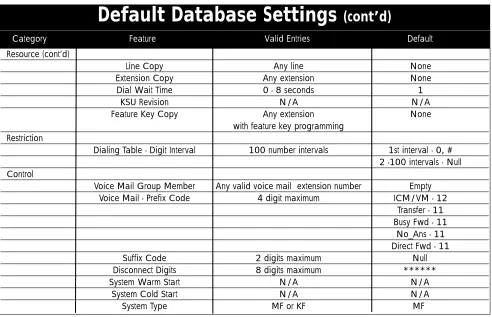
10. System Parameter Settings . . . .5-5
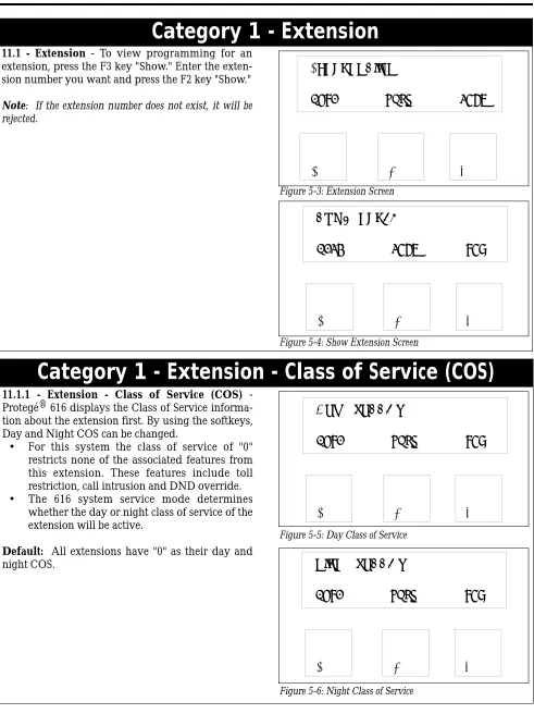
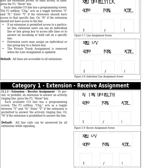
11. Enter Database Programming . . . . .5-7 11.1 Category 1 - Extension . . . .5 - 8 11.1.1 - Class of Service (COS) . . . . .5 - 8 11.1.2 - Flexible Line Assignment . . . .5 - 9 11.1.3 - Receive Assignment . . . .5 - 9 11.1.4 - Ring Assignment . . . .5 - 10 11.1.5 - Extension Group . . . .5 - 10
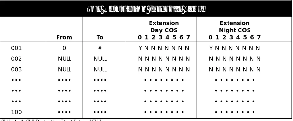
11.5 Category 5 - Restriction (cont’d.)
11.5.1.2 - Dialing Table - Ext. COS . .5 - 32 11.6 Category 6 - Control . . . .5 - 33 11.6.1 - Voice Mail . . . .5 - 33 11.6.1.1 - Prefix Code . . . .5 - 34 11.6.1.2 - Suffix Code . . . .5 - 34 11.6.1.3 - Disconnect Digits . . . .5 - 35 11.6.2 - System Warm Start . . . .5 - 35 11.6.3 - System Cold Start . . . .5 - 36 11.6.4 - System Type . . . .5 - 36
Chapter 6 Troubleshooting
1. Normal Operation . . . .6-1
2. Upgrading the System Software . . . .6-1
3. Cold Starting the System (upgrading the database) . . . .6-1
4. Troubleshooting . . . .6-2 4.1 Extensions . . . .6-2 4.1.1 Accessing An Outside Line . . . .6-2 4.1.2 Answering ICM or Incoming Call .6-2 4.1.3 Busy Display Phone Does Not Ring 6-2 4.2 System . . . .6-2 4.2.1 Heartbeat LED Is Not Lit . . . .6-2 4.2.2 DB Setup Failure . . . .6-2 4.2.3 LED Is Lit Solid Red . . . .6-2
Figures
1 - 1: Protegé® 616 Key Service Unit . . . .1-2 2 - 1: Protegé® 616 Key Service Unit Side View .2-3 3 - 1: Protegé® 616 Key Service Unit . . . .3-3 3 - 2: Protegé® 616 Common Control Board . . .3-4 3 - 3: EPROM removal . . . .3-4 3 - 4: 3x8 Expansion Board Installation . . . .3-5 3 - 5 : Cable to terminal block connection . . . . .3-6 3 - 6: Protegé station modular jack connections . .3-7 3 - 7: Attach handset cord. . . . .3-8 3 - 8: Attach keyset baseplate for desk mount . . .3-8 3 - 9: Position cradle tab for wall mount . . . .3-9 3 - 10: Attach keyset baseplate for wall mount . .3-9 5-1: Database Password Screen . . . .5-2 5-2: Password entry screen for Database
Programming. . . . .5-7 5-3: Extension Screen . . . .5-8
5-52: System Time Screen . . . .5-23 5-53: System Time Year Screen . . . .5-23 5-54: System Time Month Screen . . . .5-23 5-55: System Time Day Screen . . . .5-23 5-56: System Time Weekday Screen . . . .5-23 5-57: System Time Hour Screen . . . .5-23 5-58: System Time Minute Screen . . . .5-23 5-59: User Names Screen . . . .5-24 5-60: User Name Programming Screen . . . .5-24 5-61: Attendant Screen . . . .5-24 5-62: Alternate Attendant Screen . . . .5-25 5-63: Night Switching Screen . . . .5-25 5-64: Night Switching by Day Screen . . . .5-25 5-65: Night Switching Start Programming Screen5-25 5-66: Night Switching End Programming Screen 5-25 5-67: Database Password Screen . . . .5-26 5-68: Premises Message Screen . . . .5-26 5-69: Out for Lunch Screen . . . .5-26 5-70: Be Back SoonScreen . . . .5-26 5-71: Left for the Day Screen . . . .5-26 5-72: In a Meeting Screen . . . .5-26 5-73: Out of Office Screen . . . .5-26 5-74: On Vacation Screen . . . .5-26 5-75: System Speed Dial Screen . . . .5-27 5-76: System Speed Dial Programming Screen .5-27 5-77: Line Copy Screen . . . .5-27 5-78: Line Copy From Screen . . . .5-27 5-79: Line Copy To Screen . . . .5-27 5-80: Extension Copy Screen . . . .5-28 5-81: Extension Copy From Screen . . . .5-28 5-82: Extension Copy To Screen . . . .5-28 5-83:KSU Revision Screen . . . .5-28 5-84:KSU Revision Number Screen . . . .5-28 5-85: Feature Key Copy Screen . . . .5-29 5-86: Key Copy From Screen . . . .5-29 5-87: Key Copy To Screen . . . .5-29 5-88: Restriction Screen . . . .5-30 5-89: Dialing Table Screen . . . .5-30 5-90: Digit Interval Screen . . . .5-31 5-91: Digit Interval Starting Digit Screen . . . .5-31 5-92: Digit Interval Ending Digit Screen . . . .5-31 5-93: Extension Class Of Service Screen . . . . .5-32 5-94: Extension Day Allowed COS Screen . . . .5-32 5-95: Extension Night Allowed COS Screen . . .5-32 5-96: Extension COS Screen . . . .5-32 5-97: Extension COS Screen . . . .5-32 5-98: Control Screen . . . .5-33 5-99: Voice Mail Screen . . . .5-33
5-100: Voice Mail Group Member Screen . . . .5-33 5-101: Voice Mail Individual Member Screen . .5-33 5-102: Voice Mail Prefix Code . . . .5-34 5-103: ICM/VM Screen . . . .5-34 5-104: Transfer Screen . . . .5-34 5-105: Busy Forward Screen . . . .5-34 5-106: No Answer Forward Screen . . . .5-34 5-107: Direct Forward Screen . . . .5-34 5-108: Voice Mail Suffix Code Screen . . . .5-34 5-109: Voice Mail Disconnect Digits Screen . . .5-35 5-110: System Warm Start Screen . . . .5-35 5-111: System Warm Start Password Screen . . .5-35 5-112: System Warm Start Confirmation Screen 5-35 5-113: System Cold Start Screen . . . .5-36 5-114: System Cold Start Password Screen . . . .5-36 5-115: System Cold Start Confirmation Screen .5-36 5-116: System Type Screen . . . .5-36
Tables
Notice
This addendum reflects current Sprint Products Group standards, and its contents are subject to change without notice. While every effort has been made to avoid errors, Sprint Products Group dis-claims liability for difficulties arising from interpre-tation of information contained herein.
Electro-Static Discharge Warning
Internal components of the Protegé 616 KSU and dig-ital keysets are static sensitive. Handle expansion boards by the edges only and keep replacement com-ponents in their protective case until installation. Do not bend or touch component pins or subject them to static discharge. When working with an open 616 KSU or digital keyset, use an anti-static wrist strap and cover the work surface with anti-static material. Any static charge (no matter how small) must be dis-charged from the body before touching any internal components. The warranty for this equipment does not cover damage caused by static or mishandling. Modules or components damaged in such a manner will not be replaced.
Hazardous Voltage Warnings
The equipment owner is responsible for protecting the equipment from hazardous voltages.
The Protegé 616 system was submitted to a Nationally Recognized Testing Laboratory (NRTL), such as ETL, for safety approvals. Before installation, check your local electrical codes for installation of telephone and electronic equipment.
The following safety information is from UL 1459, Issue 2, a product safety specification governing tele-phone equipment.
Important Safety Instructions
When using your telephone equipment, the basic safety precautions described below should always be followed to reduce the risk of fire and electric shock.
1. Read and understand all instructions.
2. Follow all warnings and instructions marked on the product.
3. Unplug this product from the wall outlet before cleaning. DO NOT use liquid or aerosol cleaners.
4. Do not use this product near water (for exam-ple, in a wet basement).
5. Do not place this product on an unstable cart, stand, or table. The product may fall, causing serious damage to the product.
6. Slots and openings in the KSU are provided
for ventilation to protect it from overheating. These openings must not be blocked or cov-ered. The KSU should never be placed near or over a radiator or heat register. The KSU should not be installed in an enclosed cabinet unless proper ventilation is provided.
7. This product should be operated only from the type of power source indicated in the manual. If you are not sure of the type of power source to your building, consult your local power company.
8. Do not allow anything to rest on the power cord. Do not locate this product where the cord may be damaged by persons walking on it.
9. Do not connect an extension cord to this prod-uct's power cord. The AC outlet used for the system should not be used for any other elec-trical equipment.
10. Do not push objects into this product through the cabinet grill. They may touch dangerous voltage points or short parts that could result in a risk of fire or electric shock. Never spill liquid of any kind on this product.
11. To reduce risk of electric shock, do not disas-semble this product. Take it to a qualified service technician when service or repair is required. Opening or removing covers may expose personnel to dangerous voltages or other risks. Incorrect re-assembly can cause electric shock when the product is subse-quently used.
12. Unplug this product from the wall outlet and contact qualified service personnel for the following conditions:
a. When the power supply cord or plug is damaged or frayed.
b. If liquid has been spilled into the product. c. If the product has been exposed to rain or
water.
d. If the product does not operate normally; adjust only those controls covered by the operating instructions. Improper adjust-ment may cause damage and often requires extensive work by a qualified technician to restore normal operation.
e. If the product has been dropped or the cabi-net has been damaged.
f. If the product exhibits a distinct change in performance.
13. Never use a telephone (other than a cordless phone) during an electrical storm.
14. Do not use the telephone to report a gas leak in the vicinity of the leak.
16. Never install telephone jacks in wet locations unless the jack is specifically designed for wet locations.
17. Never touch uninsulated telephone wires or terminals unless the telephone line has been disconnected at the network interface.
18. Use caution when installing or modifying tele-phone lines.
FCC REGULATIONS
Instructions to comply with FCC Regulations:
System Registration: In some states, the tariff laws concerning the connection of multi-telephone system require that the FCC number be reported to the tele-phone company to signify the type of installation. The Protegé system has two FCC regulation numbers for each KSU type corresponding with two modes of operation. Before contacting the telephone company to order telephone lines, determine the proper FCC number from the label on the KSU. The two opera-tion modes are:
"MF" - Fully protected multi-function system,
"KF" - Fully protected key system.
The Protegé 616 System FCC Registration Num-bers are:
MF = FTZTAI-35688-MF-E
KF = FTZTAI-35689-KF-E
Only report the "KF" number if lines can only be accessed singly by pressing line keys on the keysets. If any type of pooled access to Central Office lines is available (including LCR, line routes, or even the capability of dialing 9 to search for a free outside line) the "MF" number should be reported.
Notification Requirements: The Protegé 616 equip-ment is registered with the Federal Communications Commission under Part 68 Rules and Regulations for direct connection to the telephone network. Read and follow the instructions below to comply with FCC regulations.
Terminal Equipment or Protective Circuitry: This equipment complies with Part 68 of the FCC Rules and Regulations. The information containing the FCC Registration number and ringer equivalence number (REN) is located on the label of this equip-ment. If requested, this information must be pro-vided to the telephone company.
The following information must be provided to
the telephone company, if requested.
USOC = RJ25C
Service Order Code = 9.0F
Facility Interface Code = O2LS2
REN: 1.5B
The REN is used to determine the quantity of devices that may be connected to the telephone line. Excessive RENs on the telephone line may result in the devices not ringing in response to an incoming call. In most, but not all areas, the sum of the RENs should not exceed five (5.0). To be certain of the num-ber of devices that may be connected to the line, as determined by the total RENs, contact the telephone company to determine the maximum REN for the area.
Notify the telephone company upon final discon-nect of such equipment or circuitry from the particu-lar line(s).
Systems Assembled with Individually Registered Terminal Equipment or Protective Circuitry:Notify the telephone company before connecting any system assembled with individually registered ter-minal equipment or protective circuitry to the tele-phone network. Supply the following information for each line:
1. Any information required for compatible operation of the equipment with telephone company communications facilities.
2. The FCC Registration Numbers for all equip-ment dedicated to the line.
3. The largest ringer equivalence that will be pre-sented to the line.
4. A list of FCC Registration Numbers for all equipment to be used in the system.
Connection Guidelines:Follow the guidelines below when connecting Protegé components with the tele-phone network.
1. Install equipment as specified in this manual. 2. Do not use party lines or coin lines.
3. If trouble occurs, disconnect the registered equipment from the telephone lines to deter-mine if the equipment is malfunctioning. If the equipment is malfunctioning, stop using it until the problem is corrected.
4. The telephone handsets supplied with this equipment are Hearing Aid Compatible (HAC).
remain on the line and briefly explain to the dispatcher the reason for the call. Program and test emergency numbers in off-peak hours during the early morning or late evening. 6. This equipment is capable of providing access
to interstate operator services through the use of equal access codes. Modifications by aggre-gators to alter these capabilities is a violation of the Telephone Operator Consumer Services Improvement Act of 1990 and Part 68 of the FCC Rules.
Canadian Rules
Special Notice
The Canadian Department of Communications label identifies certified equipment. This certification means that the equipment meets certain telecommu-nications network protective, operational and safety requirements. The Department does not guarantee the equipment will operate to the user's satisfaction. Before installing this equipment, users should ensure that it is permissible to be connected to the facilities of the local telecommunications company. The equip-ment must also be installed using an acceptable method of connection. The customer should be aware that compliance with the above conditions may not prevent degradation of service in some situ-ations.
Repairs to certified equipment should be made by an authorized Sprint Products Group repair facility. Any repairs or alterations made by the user to this equipment or equipment malfunctions, may give the telecommunications company cause to request the user to disconnect the equipment.
Users should ensure for their own protection that the electrical ground connections of the power utility, telephone lines and internal metallic water pipe system, if present, are connected together. This pre-caution may be particularly important in rural areas.
CAUTION: Users should not attempt to make such connections themselves, but should contact the appropriate electric inspection authority, or electri-cian, as appropriate.
LOAD NUMBER: The LOAD NUMBER (LN) assigned to each terminal device denotes the percentage of the total load to be connected to a telephone loop which is used by the device, to prevent overloading. The termination on a loop may consist of any combina-tion of devices subject only to the requirements that the sum of the load numbers of all devices does not exceed 100.
Certification Number: 2760 11075A
NOTICE
This digital apparatus does not exceed the Class A limits for radio noise emissions from the digital apparatus as set out in the Radio Interference Regu-lations of the Canadian Department of Communica-tions.
Le present appareil numerque n'emet pas de bruits radioelectriques depassant les limites applica-bles auq appareils numeriques de Classe A radioelec-trique dans le reglement sur le brouillage radioelectrique edits par le Ministere des Communi-cations du Canada.
Repairs
If trouble is experienced with the Protegé 616 system, please contact Sprint Products Group at 1-800-791-1110 for repair, return authorization, or warranty information. A return authorization must be obtained from Sprint Products Group before any products may be returned to Sprint Products Group.
Toll Fraud
WHILE THIS DEVICE IS DESIGNED TO BE REA-SONABLY SECURE AGAINST INTRUSIONS FROM FRAUDULENT CALLERS, IT IS BY NO MEANS INVULNERABLE TO FRAUD. THEREFORE NO EXPRESS OR IMPLIED WARRANTY IS MADE AGAINST SUCH FRAUD INCLUDING INTER-CONNECTION TO THE LONG DISTANCE NET-WORK.
Privacy
WHILE THIS DEVICE IS DESIGNED TO BE REA-SONABLY SECURE AGAINST INVASION OF PRI-VACY, IT IS BY NO MEANS INVULNERABLE TO SUCH INVASIONS, THEREFORE NO EXPRESSED OR IMPLIED WARRANTY IS MADE AGAINST UNLAWFUL OR UNAUTHORIZED UTILIZATION WHICH RESULTS IN THE INVASION OF ONE'S RIGHT OF PRIVACY.
Music Copyright and Broadcast
Restrictions
Limited Warranty
Sprint Products Group, Inc. provides original pur-chasers with a limited warranty against defects in material and workmanship on this product for two (2) years from date of purchase. This two (2) year limited warranty is extended only to original pur-chasers. This warranty does not apply to defects or malfunctions caused by abuse, accident, modifica-tion, negligence, or any other damage not resulting from defects in material or workmanship or for rea-sons beyond the control of Sprint Products Group, Inc.
THIS WARRANTY SPECIFICALLY EXCLUDES THE IMPLIED WARRANTIES OF MER-CHANTABILITY AND FITNESS FOR A PARTICU-LAR PURPOSE. THIS WARRANTY IS IN LIEU OF AND EXCLUDES ANY CLAIMS BY THE PUR-CHASER FOR CONSEQUENTIAL OR INCIDEN-TAL DAMAGES. Some states do not allow the exclusion of consequential or incidental damages, in which case the foregoing exclusion may not apply to you. This warranty gives you specific legal rights, and you may have other legal rights which vary from state to state. In accordance with the Federal Com-munications Commission regulations, repair of this equipment must be performed by Sprint Products Group, Inc. or an authorized agent.
Servicing Instructions
Equipment requiring servicing should be returned to place of purchase, whenever possible. Otherwise, call 1-800-791-1110 to request a Material Return Authorization (MRA) number and obtain return instructions.
Sprint Products Group, Inc. assumes no responsi-bility for equipment received damaged due to improper packing or shipping. No responsibility is assumed for the repair and/or return of foreign attachments such as adapter plugs, extra length cords, etc.
If inspection by Sprint Products Group, Inc. deter-mines the defective equipment to be covered by war-ranty, it will be repaired and returned to you at no cost.
Equipment received with damage due to abuse, inadequate packing, improper shipping or handling, or due to some other warranty noncompliance, will be repaired on a billable basis based on the cost of labor and parts. The equipment will be returned to you at your expense.
If this equipment is returned to Sprint Products Group, Inc. in a complete and undamaged condition after the two (2) year warranty period has expired, Sprint Products Group, Inc. will repair the
The Protegé® 616 Installation and Maintenance Man-ual provides the information necessary to install, program, operate and maintain the Protegé digital, hybrid key system. Sprint Products Group, Inc. pro-vides this document as a guide for telephone installers and service personnel.
The contents of this manual are subject to revision or change without notice.
It contains five chapters.
1) Introduction: an overview of the Protegé 616 system.
2) Specifications: detailed technical specifications and requirements.
3) Installation: a pre-install checklist and instruc-tions required to install the system.
4) Features: descriptions of the 616 features. 5) Programming: instructions on programming
the 616 systems.
1. 616 System Overview
The Protegé 616 is the newest addition to the Protegé key system family. It supports the 26 Button Business with Display and the 17 Button Business without Display digital keysets. It also works with an analog adapter that provides support for single-line tele-phones and other analog devices like fax machines and modems.
Protegé 616 comes ready-to-use with a default software configuration. The software can be customized to meet customer requirements from the Business with Display keyset.
1.2 616 Capacity
The 616 comes equipped with three lines and eight digital extension ports. The system can be expanded to a maximum capacity of 6 lines and 16 digital extensions by installation of an optional 3x8 expan-sion board. Each digital extenexpan-sion port can be
modi-fied with the use of an Analog Adapter to provide two analog ports. The maximum number of analog extension ports possible is 30.
2. Hardware Summary
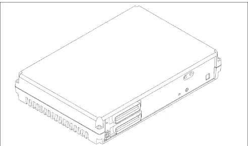
A single self-enclosed cabinet houses most of the 616 system components. See Figure 1-1. The cabinet can be mounted on a wall. The cabinet comes fully equipped to support many small business applica-tions such as external paging, music on hold, power failure transfer and voice mail integration.
2.1 3x8 Expansion Board
An optional 3x8 expansion board can be installed in the 616 KSU to expand the system capacity to 6 lines and 16 digital extensions. Material code 436052.
2.2 Optional Analog Adapter
A standalone analog adapter can be connected to a digital port. The adapter splits the "B" channels to connect up to two analog devices. Each analog adapter includes two DTMF receivers and two tone detectors. Material code 436370.
2.3 Station Instruments
The 616 system supports the 26 Button Business with Display and the 17 Button Business without Display digital keysets. A standard single line telephone can be used on the system with the use of the optional analog adapter. The single line phone does not sup-port 90V DC message waiting.
2.4 Optional Peripheral Equipment
The system supports an external music source (for music-on-hold or background music) and external (single, one-way) paging equipment can be con-nected to the system.Figure 1 - 1: Protegé® 616 Key Service Unit (with optional 3x8 Expansion Board installed).
3. Software Summary
Protegé 616 systems are shipped ready for immedi-ate use with a default software configuration. The default configuration can be modified or completely replaced to satisfy specific customer requirements. Protegé 616's database can be entered and changed, under password control, from any Business Display keyset.
Protegé digital keysets are shipped ready for immediate use with a default configuration. The key-set configuration can be altered through system pro-gramming or from individual stations.
3.1 Features Overview
The Protegé 616 feature set contains many features that are normally found on larger key systems. Some of these features include: call abandon, class of service, distinctive ring, power failure transfer, pri-vate line, toll restriction and many more. A complete listing of features can be found in chapter 4 "Fea-tures" of this manual.
4. Installation,
Program-ming and Maintenance
4.1 Installation Summary
Installation of the Protegé 616 is straightforward. In-depth information can be found in chapter 3 "Instal-lation," including step-by-step information on the installation process.
4.2 Programming Summary
The 616 comes ready for immediate use with a default software configuration. Additional program-ming can be accomplished through the use of a Busi-ness Display keyset.
4.3 Maintenance Summary
Protegé 616 requires no routine/scheduled maintenance. Peripheral equipment, such as battery backup units, may require routine maintenance. Check the instructions provided with the equipment for maintaining these items.
4.4 Keyset User Guides
keyset, and the single line telephone. The cards and user guides can be ordered separately.
4.5 Liability Disclaimer
This chapter provides hardware specifications for the Protegé® 616 digital hybrid key telephone system and related components. An overview of the specifics of the 616 software is provided in chapter 4, "Features," and chapter 5, "Programming." Steps for installing the 616 system are provided in chapter 3, "Installation," of this manual.
Every effort has been made to ensure that the information in this chapter is accurate and compre-hensive. However, Sprint Products Group disclaims liability for difficulties ensuing from interpretation of the information contained herein. Furthermore, SPG
disclaims liability for any configuration or utilization not specifically provided in this manual and shall have no liability for the product in the event of unau-thorized modifications.
1. System Resource
Capacity
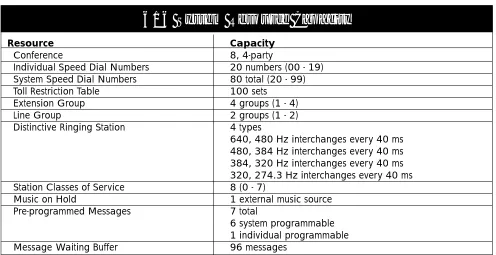
Table 2 - 1 offers a listing of the system resource capacities for such resources as Speed Dial numbers, conferencing, and pre-programmed messages.
2 Specifications
Resource Capacity
Conference 8, 4-party
Individual Speed Dial Numbers 20 numbers (00 - 19)
System Speed Dial Numbers 80 total (20 - 99)
Toll Restriction Table 100 sets
Extension Group 4 groups (1 - 4)
Line Group 2 groups (1 - 2)
Distinctive Ringing Station 4 types
640, 480 Hz interchanges every 40 ms 480, 384 Hz interchanges every 40 ms 384, 320 Hz interchanges every 40 ms 320, 274.3 Hz interchanges every 40 ms
Station Classes of Service 8 (0 - 7)
Music on Hold 1 external music source
Pre-programmed Messages 7 total
6 system programmable 1 individual programmable
Message Waiting Buffer 96 messages
616 System Resource Capacity
2. Cabling and MDF
Cabling and wiring used for the 616 system should meet or exceed the following specifications.
2.1 Wiring Overview
Connections between CO lines, station instruments, external equipment and the 616 board are made at the Main Distribution Frame (MDF). See Figure 2-1.
For standard telephony wiring, the MDF usually consists of a 3/4" wood backboard mounted on a wall in the utility closet where the system switching components will be installed. One standard 66M1-50 type terminal block is attached to the backboard for the actual wire connections.
2.2 Station Wiring
Protegé station equipment requires unshielded, twisted pair (UTP) 24-gauge cable. Each station uses only one wire pair. For convenience in terminating, however, two pair is recommended. The second pair can be used as a backup connection if the first pair is damaged. All unused pairs should be grounded at the MDF.
The station cable runs must not exceed the lengths listed in Table 2-2: Maximum Loop Distance and Cable Resistance.
2.3 Interface Cable
The Protegé 616 KSU and 3x8 expansion board each require one 25-pair amphenol-type (male-ended) interface cable for terminating the CO lines and digi-tal extensions. This cable may be purchased in a 2-3 foot length with a 66M1-50 block already terminated. Alternatively, the cable can be prepared on site. Instructions on preparing this cable are not included in this manual.
2.4 Grounding Cables
Sprint Products Group highly recommends ground-ing all unused cable pairs at the MDF to an earth ground point.
2.5 Station Modular Jacks
Terminate station cable runs on modular jacks mounted near where the station instrument will be placed. Each station requires a 1-pair connection.
2.6 Terminal Block
Use one 66M1-50 style terminal block to terminate the KSU interface cable for station and line connec-tions. Terminate the KSU interface cable on the right side of the block. Terminate the station and line cables on the left side of the block. Each line and sta-tion cable requires a two-wire connecsta-tion. Use bridg-ing clips to complete the connection after the terminal block has been punched down.
Important: Make sure that the system power is off while making terminal block connections. Shorting punch block terminals together can damage the KSU.
2.7 Phono Jack Connections
The KSU has two mono, 1/8" mini-phono jacks. These can be used for external music source and external paging. The music source's optimum input level is 0 dB, 600 ohm input impedance. The external paging source's optimum output level is 0 dB, 600 ohm output impedance.
Type of Extension Digital
Analog
Loop Distance 1312 ft (400m) 1312 ft (400m)
Cable Resistance 70 ohms 70 ohms
Maximum Loop Distance
and Cable Resistance
3. Equipment Cabinet
3.1 Protegé 616 KSU
The 616 Key Service Unit (KSU) houses the main Printed Circuit Board and Central Control Board. The main printed circuit board provides interface for three loop-start CO lines and eight key telephones. The Central Control Board performs all the control functions including digital voice and data communi-cations.
The design of the KSU includes a conductive paint on the inside cover that acts as a ground path to the ground lug connection on the side of the KSU. Protection from over-current is provided by a fuse, which is rated 5A, in the power transformer.
3.2 Protegé 616 Power Supply
A power adapter is included with the KSU. It pro-vides electrical power to the internal components of the KSU and to all station instruments except analog adapters. Power is applied or removed from the unit by plugging and unplugging the AC adapter from the AC outlet. Connect the adapter cord to the KSU before the AC adapter is plugged into the AC outlet.
4. Internal Components
4.1 3x8 Interface Board &
3x8 Expansion Board
The main PCB (also known as Motherboard) consists of the following circuits:
• Eight digital extension interface circuits • Three loop-start CO lines
• Lightning surge protection • Ring detection
• Polarity guard
• Loop relay and associated snubber circuit • Darlington electronic choke
• Radio frequency noise filter
• Coupling/isolation transformer, impedance 600:600 • Voice signal limiter with Zener diodes
• Hybrid circuit with complex impedance • Balance network
• COMBO circuit for analog to digital interface • Caller ID detection circuitry
Cabinet Dimensions
Height 12.9 in. (330 mm)
Width 8.8 in. (224.5 mm)
Depth 2.8 in. (71.5 mm)
Cabinet Weight
616 KSU 3.36 lb. (1.53 kg)
Electrical Characteristics
Input 120VAC, 60Hz (20-36VDC)
Output 24 VDC. 1 Amp
Power Consumption 54 Watts
616 Cabinet Characteristics
Table 2 - 3: 616 Cabinet Characteristics.
Figure 2 - 1: Side View of Protegé® 616 Key Service Unit with the optional 3x8 Expansion Board installed showing connectors
1/8" phone jacks for External Paging Music On Hold
Reset Switch
Heartbeat LED
4.2 Central Control Board
This board contains all circuitry to control the fully equipped KSU. There is an internal connector between the main PCB and the Central Control Board. The Central Control Board contains:
• An 8088-compatible 16-bit microprocessor • 512 Kbyte ROM chip containing system software • 128 Kbyte CMOS RAM with battery backup • Interrupt controller
• Time slot interchange circuit • Digital conference circuit
• System heartbeat indicating red LED
• System timing circuit and PCM frame timing circuit • CPU/RAM reset switch for initialization
4.3 Auxiliary Board
This board contains circuitry for connecting to exter-nal input and output devices (music source and pag-ing equipment).
5. Optional System
Components
5.1 3x8 Expansion Board
One 3x8 Expansion Board may be installed in the 3x8 KSU to expand the system to a maximum capacity of 6 lines and 16 digital extensions.
5.2 Analog Adapter
Analog Adapters can be connected to any of the digi-tal station ports.
5.3 Station Instruments
Protegé® 616 supports the Business with Display and Business without Display keysets. Additionally the 616 system works with single-line phones, fax machines and voice mail systems that must be con-nected to the 616 KSU via an analog adapter.
6. Optional Equipment
6.1 Music on Hold/Background Music
Radios, CD players, tape players and other audio sources can be connected to the external music porton the KSU. The external source is mono and the impedance must be 600 ohms to match the input impedance of the external music port.
Note: Broadcast music sources are subject to copyright restriction.
6.2 Voice Mail
Commercial voice mail systems can be attached to an analog adapter port. The interface requirements for a voice mail system are the same as those for an indus-try standard single line phone.
6.3 Fax
Commercial fax equipment can be attached to an analog adapter port. The interface requirements of a fax system are the same as those for an industry stan-dard single line phone.
6.4 External Paging
The 616 KSU provides a single paging port. It has an output impedance of 600 ohms. If an external paging unit is connected to a Protegé® system, its input impedance also should be 600 ohms to match. Matching impedances ensures maximum output from the pager and noise free operation. The page port output is 0 dBm.
6.5 Power Failure Transfer
Power failure transfer provides a bypass for outside line calls during power failure with no backup bat-teries or after the backup batbat-teries have been depleted. This is a hardwired feature. The system automatically switches the first line to an optional dedicated analog telephone connected to the 66M1-50 block. During Power Failure Transfer, incoming calls on line 1 only ring at this analog phone. The phone also may be used to place outgoing calls for assistance.
7. Station Instruments
7.1 Common Keyset Features
The two keysets share a common set of basic fea-tures. These include a reversible baseplate for desk-top or wall-mounting use, eight levels of voice and ringer volume control, single-pair wire installation, 10-foot coiled handset cord, dual colored LEDs, headset compatibility, speakerphone, programmable feature keys and seven fixed keys for the most user features:
Hold- places calls on hold
XFR/CONF - transfers calls or establishes a conference call
Clear- disconnects call or exits programming
Function- accesses system features
Vol(up) - increases voice/ring volume
Vol (down) - decreases voice/ring volume
Speaker- activates the built-in speakerphone
In addition to the above seven keys, each keyset includes a "Redial" key that can be reprogrammed for another system feature if desired.
Each keyset also includes programmable function feature keys. These keys can be programmed with functions such as Do Not Disturb, Call Forwarding or dialing a directory number to access other extensions.
7.2 Business Keyset with Display
The Business 15DCL Keyset with Display is a 26 but-ton phone that has 16 programmable feature keys, 15 of which have dual color LEDs. The Business with Display has a dedicated headset jack and includes an LCD panel that has three interactive function keys (F1, F2 and F3) for feature selection and program-ming.
7.3 Business Keyset
The Business Keyset is a 17-button phone that has nine feature keys with dual color LEDs. The Business Keyset is the basic Protegé station instrument.
Feature
Key Number Content Detail
1 1 Co Line
2 2 Co Line
3 3 Co Line
4 10 Extension
5 11 Extension
6 12 Extension
7 13 Extension
8 14 Extension
9 15 Extension
10 ICM Intercom Key
11 F98 Voice Call
Allow
2 F2 Call Forward
13 F502 All Page
14 F4 Do Not Disturb
15 F76 Mute
15DCL Keyset with Display
Table 2 - 4: Business with Display Keyset
Feature
Key Number Content Detail
1 1 Co Line
2 2 Co Line
3 3 Co Line
4 10 Extension
5 11 Extension
6 ICM Intercom Key
7 F22 Direct Call
Forward
8 F4 Do Not Disturb
9 F76 Mute
9DCL Keyset without Display
This chapter explains how to install the Protegé® 616 digital hybrid key system. It includes detailed instal-lation steps specific to the Protegé system. Installers should know standard telephony and data wiring techniques. This manual does not give detailed steps for standard techniques.
1. Installation Overview
1.1 Installation Steps
The following list briefly describes each step in the installation process. The steps are listed in the recom-mended order of completion.
1) Read the Installation Chapter. Installers should read this chapter before installing the system.
2) Site Planning. The position of the Protegé system components should be determined before the installation begins. A floor plan showing station positions and cabling should be developed.
3) Install the MDF. The Main Distribution Frame is usually a 3/4 inch wooden backboard, mounted on a wall. Attach the punch down terminal block onto the backboard. Station wiring and CO lines are connected at the MDF. 4) Install Programming Software. Before mount-ing the KSU on the MDF backboard, remove the four screws that hold the front panel in place. Install the software.
5) Install KSU. Mount the KSU on the MDF back-board. Use the provided mounting template to aid in spacing the mounting screws.
6) Attach Interface Cables. The 616 KSU is con-nected to the 66M1-50 terminal block on the MDF.
7) Station Cabling. Each Protegé station requires one twisted-pair, 24 AWG connection. The use
of two twisted-pair, 24 AWG wire is recom-mended. Station cabling is terminated on the 66M1-50 block at the MDF and four conductor modular jacks at the station.
8) CO Line Cabling. Terminate the CO lines on the 66M1-50 block at the MDF.
9) Install Station Equipment. Protegé digital key-sets and analog devices require basic assembly and connection.
10) Install Optional System Equipment. Optional system equipment might include music on hold devices or external paging equipment. 11) System Initialization. Change the RAM slide
switch from the factory default RESET to ON. Once this has been done and all components have been set up and all connections have been made, the Protegé system can be initial-ized. The system boots up with default pro-gramming that can be changed to suit individual customer requirements. Program-ming information is found in chapter 5, "Pro-gramming."
1.2 Preliminary Checklist
To make installation easier, the following items should be checked before beginning the 616 installa-tion.
1.3 Location
At most sites the Key Service Unit (KSU) or Main Distribution Frame (MDF) will be installed in a util-ity closet or similar isolated space. Wherever the KSU and MDF are installed, they must not be exposed to direct sunlight, high humidity, heat, dust, strong magnetic fields (such as those generated by electrical motors and copy machines), or Radio Fre-quency Interference (RFI) fields (such as those gener-ated by radio or television broadcasting equipment). The location chosen should be centrally located to simplify wiring. Be sure that no station wiring exceeds the maximum length listed in the Maximum
Loop Distance and Cable Resistance Table 3-3 on page 3-6. The table assumes the use of twisted pair 24 AWG wire.
1.4 Power Requirements
The KSU cabinet must be within 5 feet (1.5 meters) of the isolated, dedicated, 105 - 125VAC, 57 - 63Hz, 15A, single-phase commercial power receptacle. No other equipment may be connected to the dedicated cir-cuit.
A surge protector should be used to protect the KSU from power surges and voltage spikes.
1.5 Environmental Conditions
As a general rule, if environmental conditions are suitable for office personnel, they also are suitable for Protegé equipment. The KSU may be safely operated in temperatures ranging from 32° to 104° Fahrenheit (0° to 40° Celsius), in relative humidity ranging from 5% to 95% (non-condensing), and at altitudes up to 10,000 feet. Ensure that these conditions will not be exceeded under any circumstances (such as air con-ditioning failure and tropical depressions). A prop-erly controlled environment will extend equipment life and help ensure reliable system operation.
1.6 Installation Safety Guidelines
(From UL 1459, a product safety specification for telephone equipment.)1) Never install telephone wiring during a light-ning storm.
2) Never install telephone jacks in wet locations unless the jack is designed for use in wet loca-tions.
3) Never touch uninsulated telephone wires or terminals unless the telephone line has been disconnected at the network interface.
4) Use caution when installing or modifying tele-phone lines.
1.7 Tools and Supplies
A basic list of tools and supplies required to install the Protegé® 616 system is provided in the Tools and Supplies Table. The list is intended for standard telephony wiring practice. Sites requiring EIA/TIA568A unshielded, twisted pair wiring stan-dards require additional components.
1.8 Install MDF
The Main Distribution Frame (MDF) is where the KSU, the station equipment and CO lines are
Requirements Temperature - KSU and Keysets
Relative Humidity (non-condensing)
Altitude
In Operation 32° - 104° F (0° - 40° C)
5% - 95%
10,000 feet
In Storage -40° - 185° F (-40° - 85° C)
5% - 95%
10,000 feet
Environmental Conditions
Table 3 - 1: Environmental Conditions
Qty Description
1 Protegé® Business Display keyset for programming 1 pair Side-cutter pliers
1 pair Needle-nose pliers 1 Cable cutter
1 set Common screwdrivers 1 set Phillips-head screwdriver 1 Punch-down tool 1 Phone test set
1 High-impedance, Digital VOM, at least 0.5% accuracy
1 Grounding wrist strap 1 pair Safety glasses 1 pair Gloves
1 66M1-50 type terminal blocks Varies Bridging clips
Varies 2 Twisted-pair 24 AWG cable Varies 4-conductor modular jacks
Varies Stranded #10 AWG or larger, copper ground wire 1 Amphenol interface connector
1 fl inch wooden backboard for MDF Varies Mounting hardware for backboard
Varies Equipment for mounting MDF: drill, stud finder, tape measure, etc.
Varies Equipment for running station cables: cable puller, drop-lights, drill, etc.
Tools and Supplies
connected. Usually, the MDF is 3/4 inch wooden backboard securely mounted to a wall in the utility closet or other isolated space where the switching equipment is to be installed.
To mount the MDF on a wall, be sure to obtain a backboard large enough to accommodate the 66M1-50 terminal block, the KSU and any optional equip-ment that must be close to the KSU or MDF. The recommended material for backboards is A/C ply-wood.
Attach the backboard securely to the wall with pan or hex head screws appropriate to the wall con-struction (wood screws for wood studs, self-tapping sheet metal screws for metal studs). Use screws not less than 3.5 inches in length. Insert washers on the screws to reinforce the backboard. Center backboard mounting screws on wall studs, use drywall or other substrate anchors and increase the number of screws used to attached the backboard.
Attach the 66M1-50 terminal block to the back-board for terminating station wiring, CO lines and KSU connector.
For details on 66M1-50 block connections see “Station Cabling” in this chapter.
2. Installation
2.1 Unpack and Inspect Cabinet
1) Remove the KSU cabinet from its packaging and place on a level surface.
2) Inspect the cabinet for any damage that might have occurred in shipping and for loose or missing components.
Warning: Printed circuit boards can be damaged by static discharge. Take precautions to protect the KSU during handling.
The preferred static protection device is a grounded wrist strap worn at all times while handling the KSU. For max-imum effectiveness, make sure that the cabinet is grounded properly.
Avoid touching the electrical contacts on the boards. A static discharge on the Central Control Board may reset the 616 system.
EPROM Chip
External Paging
Music on Hold
Music / Paging Board
Amphenol Connector 616 Board
Central Control Board
Figure 3 - 1: Protegé® 616 Key Service Unit Central Control, Paging and 3x8 interface boards.
2.2 EPROM Installation
The Protegé® 616 software consists of one EPROM that must be mounted in the IC socket on the Central Control Board. Follow the steps below to mount it:
1) Connect the grounding wrist strap to an approved ground.
2) Find the anti-static bag containing the EPROM chip for the CCB.
3) Place an anti-static bag on a level surface, and, observing static discharge precautions, place the KSU on the bag.
4) Being careful not to touch the chip pins, remove the EPROM from its carrier.
5) Insert the EPROM in its socket. Align the notch on the chip with the notch on the socket. Make sure that all pins are properly seated.
6) Replace the KSU cover and the four screws that hold it in place.
7) Move the RAM switch from On to Reset. Wait 10 seconds and return the switch to the On position.
8) Follow the mounting and power connection directions below.
EPROM (U9)
Central Control Board
Figure 3 - 2: The Common Control Board of the Protegé 616 KSU.
2.3 Install Expansion Board
Some installations may require the optional 3x8 Expansion Board. Follow these steps to install the 3x8 Expansion Board in the KSU.
1) Connect the grounding wrist strap to an approved ground.
2) Remove the 3x8 Expansion Board and stand-offs (mounting posts) from the anti-static bag. 3) Remove the three mounting screws from the
installed 3x8 Interface Board and replace with the standoffs. (Do not overtighten.)
4) Remove the two screws retaining the KSU side panel insert and carefully remove the insert. 5) Align the 3x8 Expansion Board over the
stand-offs with the amphenol connector facing the opening in the KSU side panel.
6) Carefully place the 616 Expansion Board on the standoffs and secure with the screws removed in step 3.
7) Connect the ribbon cable from the 3x8 Expan-sion Board to connector JP3 on the KSU main PCB.
8) Replace the KSU cover and secure with the four cover screws.
2.4 Install KSU
The KSU can be mounted on a wall by attaching it to the 3/4 inch wooden backboard used for the MDF. See the section on "Install MDF" discussed previ-ously. Follow these steps to mount the 616 KSU.
1) Unfold the mounting template and place it on the backboard. The template can be taped on the backboard for positioning.
2) Mark the location of the two mounting screws on the template.
3) Remove the template and drill pilot holes for the mounting screws.
4) Screw the hex head screws into the two pilot holes for the mounting screws. Leave a 3/4 inch gap between the screw head and the backboard. 5) Position the KSU so that the keyhole slots in
the mounting brackets are aligned over the mounting screws. Press the cabinet in place and lower to engage the brackets.
6) Once the KSU is on the MDF, pull the KSU cab-inet gently outward to ensure that there is not too much space between the KSU backing plate and the MDF. If there is, remove the KSU, tighten the mounting screws a little and replace the KSU. Repeat step 6.
2.5 Power Connections
The KSU cabinet must be connected to a dedicated AC power receptacle as described in "Power Requirements" in this chapter. Power is applied or removed from the unit by plugging and unplugging the AC adapter from the AC outlet. Connect the adapter cord to the KSU before the AC adapter is plugged into the AC outlet.
Type of Extension Digital
Analog
Loop Distance 1312 ft (400m) 1312 ft (400m)
Cable Resistance 70 ohms 70 ohms
Maximum Loop Distance
and Cable Resistance
Table 3 - 3: Maximum Loop Distance and Cable Resistance
Cable Pair Pair Color Designation
26/1 White/Blue Station Port 1 27/2 White/Orange Station Port 2 28/3 White/Green Station Port 3 29/4 White/Brown Station Port 4 30/5 White/Slate Station Port 5 31/6 Red/Blue Station Port 6 32/7 Red/Orange Station Port 7 33/8 Red/Green Station Port 8
34/9 Red/Brown N/C
35/10 Red/Slate N/C
36/11 Black/Blue N/C
37/12 Black/Orange N/C
38/13 Black/Green N/C
39/14 Black/Brown N/C
40/15 Black/Slate N/C
41/16 Yellow/Blue N/C
42/17 Yellow/Orange N/C
43/18 Yellow/Green N/C
44/19 Yellow/Brown N/C
45/20 Yellow/Slate N/C
46/21 Violet/Blue N/C
47/22 Violet/Orange CO1
48/23 Violet/Green CO2
49/24 Violet/Brown CO3
50/25 Violet/Slate Power Failure CO1
Amphenol Connector
Pin-Out Designation
Table 3 - 4a: Pin-Out. This table provides the pin-out designa-tion for the first amphenol connector.
WH-BL BL-WH WH-OR OR-WH WH-GN GN-WH WH-BN BN-WH WH-SL SL-WH RD-BL BL-RD RD-OR OR-RD RD-GN GN-RD RD-BN BN-RD RD-SL SL-RD BK-BL BL-BK BK-OR OR-BK BK-GN GN-BK BK-BN BN-BK BK-SL SL-BK YL-BL BL-YL YL-OR OR-YL YL-GN GN-YL YL-BN BN-YL YL-SL SL-YL VI-BL BL-VI VI-OR OR-VI VI-GN GN-VI VI-BN BN-VI VI-SL SL-VI
2.6 Attach KSU Cables
The 616 requires one 24-pair connectorized cable (available from Sprint North Supply) for terminating the 3 CO lines and 8 extensions.
To connect the cable, follow these steps:
1) Attach the amphenol-type connector on one end of the cable to the connector on the 616 KSU. 2) Strip the opposite end of the cable, exposing a
sufficient amount of wiring for connection to the terminal block.
3) Follow the color code illustrated in Figure 3-4 to connect the cable to the terminal block.
2.7 Station Cabling
Protegé® stations require a star (home run) configu-ration from the KSU. Develop a floor plan before running cable to avoid problems such as overlooking or duplicating cable runs. Label both ends of each cable for easy identification.
Protegé stations require 24 AWG twisted-pair cabling. Each station uses one twisted pair. At least two-pair twisted cable is recommended for all sta-tions. The additional pair may be used to replace a bad wire pair. Each station cable should be dedicated to one telephone instrument. Sharing one cable between two instruments is not recommended.
2.8 Running Station Cable
From the MDF, run standard 24 AWG two-pair twisted cable (4 conductor) to each station position. Follow these guidelines:
1) Install proper type cable for the application according to the National Electrical Code and local building codes.
2) Avoid cable runs parallel to fluorescent light fixtures or AC lines not in conduit. If these obstacles are unavoidable, run the cables across them at right angles.
3) Do not run station cables inside electrical conduit already occupied by AC power cable. (To do so is a violation of the National Electrical Code). 4) Do not run cables near equipment with electric
motors or through strong magnetic fields, such as those generated by large copy machines, arc welding equipment, heavy motors, etc.
5) Do not place station cables where they can be stepped on or where they can be rolled over by office furniture.
6) Avoid using multi-pair (e.g. 25-pair) cable runs to multiple station locations. If multi-pair "feeder" cables are used, do not include AC-ringing sin-gle-line sets, AC-ringing auxiliary equipment, or CO lines in a cable used for digital keysets. 7) Do not exceed the loop limit measurement
(using 24 AWG wire) for the station cable-lengths as outlined in Table 3-3.
R G
BK Y
W BL
Figure 3 - 6: Modular Jack connections for Protegé station.
Cable Pair Pair Color Designation
26/1 White/Blue Station Port 9 27/2 White/Orange Station Port 10 28/3 White/Green Station Port 11 29/4 White/Brown Station Port 12 30/5 White/Slate Station Port 13 31/6 Red/Blue Station Port 14 32/7 Red/Orange Station Port 15 33/8 Red/Green Station Port 16
34/9 Red/Brown N/C
35/10 Red/Slate N/C
36/11 Black/Blue N/C
37/12 Black/Orange N/C
38/13 Black/Green N/C
39/14 Black/Brown N/C
40/15 Black/Slate N/C
41/16 Yellow/Blue N/C
42/17 Yellow/Orange N/C
43/18 Yellow/Green N/C
44/19 Yellow/Brown N/C
45/20 Yellow/Slate N/C
46/21 Violet/Blue N/C
47/22 Violet/Orange CO4
48/23 Violet/Green CO5
49/24 Violet/Brown CO6
50/25 Violet/Slate Power Failure CO4
Amphenol Connector
Pin-Out Designation
2.9 Terminating Station Cable
Station Locations:Terminate each station with a four-conductor modular jack. Connect the white/blue wire to the green terminal and the blue/white wire to the red terminal of the jack. Note: polarity is not significant for Protegé® stations, but it is a good idea to follow stan-dard telephony wiring practice (i.e., use white/blue for Tip and blue/white for Ring). See Figure 3-5.
Main Distribution Frame: Terminate the station cables on the 66M1-50 terminal block(s) at the MDF. Refer to Table 3-4 to determine the position of each station cable. Do not attach bridging clips until the loop resistance tests have been performed.
2.10 Station Loop Resistance Test
Perform the loop resistance test for each station. To perform the test, follow these steps:
1) Make sure that the bridging clips have not been installed on the 66M1-50 terminal block and that the station instruments have not been connected to the modular jacks.
2) Place a short across the red and green wires on the modular jack.
3) At the MDF, measure the resistance across the terminal posts to which the station cable is connected. The reading should not exceed the limits for 24 AWG wire listed in Table 3-3. Ohm values are the loop measurements; feet/meter values are the maximum one-way measurements from the KSU cabinet.
4) Remove the short after the test is complete.
Note: Excessive and/or improperly made connections increase the resistance of a cable, which reduces the allow-able callow-able run length.
Repeat this test for each station cable. Install
bridging clips on the station blocks to complete the cable resistance.
2.11 CO Line Connections
Central Office lines are routed from the telephone company demarcation block to the 66M1-50 terminal block. Use the CO Line Termination Table 3-5 to identify the pairs associated with each CO line.
2.12 Power Failure Transfer
In case of a power failure, Protegé automatically switches to the battery backup system for continued operation. Operation on battery backup power sup-ply is identical to normal operation.
If the battery backup becomes depleted, or if no battery backup system has been connected, Protegé automatically switches to "power failure transfer" operation.
The Line 1 circuit and Line 4, if equipped, is auto-matically switched to a designated emergency tele-phone connected to the Violet/Slate pair of the 66M1-50 terminal block. All incoming calls on Line 1 will ring at a single-line telephone and outgoing calls can be placed from this telephone. Other call pro-cessing features like transfer, conferencing and digi-tal keyset operation are not supported in the Power Failure Transfer mode.
Main 616 3x8 Exp. Board Line Board Line
1 4
2 5
3 6
Pair Color
Violet/Orange Violet/Green Violet/Brown
CO Line Termination
Table 3 - 5: C.O. Line Termination Figure 3 - 7: Press the first two inches of the handset cord into
the notched strain relief channel.
3. Install Protegé Digital
Keysets
Unpack each unit. A complete installation uses all of the items on the packing list. Report missing or damaged items to Sprint Products Group for replacement or credit.
3.1 Insert Overlay and Directory Card
1) Write the extension number on the line/featurekey overlay. Place the overlay on the keyset. 2) Place the protective cover on the line/feature
key overlay. Lock the cover in place by insert-ing the tabs into the keyset slots.
3) Insert the retractable directory card into the baseplate retaining channel.
3.2 Desk Mounting:
1) Turn the keyset over and place it facedown on a table. Plug one end of the coiled handset cord into the jack labeled "Handset." Press the first two inches of the handset cord into the notched strain relief channel. See Figure 3-6. 2) Plug one end of the gray line cord into the jack
labeled "Line."
3) Turn the baseplate upside down. Insert the base-plate hooks into the upper slots of the keyset. The raised end of the baseplate should face the line jack at the top of the phone. See Figure 3-7. 4) Rotate the baseplate down. The tab on the
baseplate should contact the lower keyset slot labeled "Open." Press the baseplate tab until it snaps into place with an audible click.
5) Turn the keyset and attached baseplate over. Place it on its designated desk.
6) Plug the free end of the coiled handset cord into the jack on the handset. Place the handset in its cradle.
7) Plug the free end of the gray line cord into the wall-mounted modular jack.
3.3 Wall Mounting
1) Lift the cradle tab and rotate it 180° until it clicks into the keyset. See Figure 3-8.
2) Turn the keyset over and place it facedown on a table. Plug one end of the coiled handset cord into the jack labeled "Handset." Press the first two inches of the handset cord into the notched strain relief channel. See Figure 3-6. 3) Thread one end of the gray line cord through a
square hole in the baseplate and plug the cord into the jack labeled "Line."
4) Turn the baseplate upside down and insert the baseplate hooks into the lower slots of the key-set. The raised end of the baseplate should face the handset jack at the bottom of the phone. See Figure 3-9.
5) Rotate the baseplate down. The tab on the baseplate should contact the upper keyset slot labeled "Open." Press the baseplate tab until it snaps into place.
6) Align the holes in the baseplate over the studs of the wall-mounted plate. Press downward until the baseplate locks into place.
7) Plug the free end of the coiled handset cord into the jack on the handset. Place the handset on its cradle.
Figure 3 - 9: For a wall mount, lift the cradle tab and rotate it 180° until it clicks into the keyset. Changing the cradle tab ori-entation holds the handset in position.
8) Plug the free end of the gray line cord into the wall mounted modular jack.
3.4 Install Single-Line Phones and
Analog Devices
Follow the instructions provided with the single-line phone or analog device for installation and connec-tion. Singleline phones and analog devices must be connected to analog adapters connected to the 6/6 KSU. Some analog devices, like voice mail systems, may require additional software configuration. See chapter 4, "Features," and chapter 5, "Programming," for more information.
4. Install Optional
Peripheral Equipment
Follow the instructions provided with optional peripheral equipment. Such equipment may include external paging systems and music on hold devices.
5. System Initialization
When the installation steps explained in this chapter have been completed, the 616 system can be initial-ized. Initialize by following these steps:
1) Ensure that the AC power cord is not con-nected.
2) Turn the Ram Switch to the Reset position. 3) After 10 seconds, return the switch to the ON
position.
4) Connect the AC power cord.
5) Watch the red heartbeat LED for a flashing heartbeat. It should begin after four to six seconds. The Protegé® 616 system has now completed initialization and the default data-base is loaded. Turn to chapter 5, "Program-ming," for more information about customizing the database.
Important
The AC Adapter must be either plugged into or unplugged from the AC outlet to apply or remove
This chapter explains the features that function on the Protegé® 616 system. These features may func-tion slightly differently than the features on the Protegé CTX, MTX and LTX. Please read through the features carefully. Included with each feature description is either the display keyset Function codes or the location in database for programming the feature.
1. System Features
1.1 Alphanumeric Display
DATABASE PROGRAMMING - NONE
All display keysets provide a two-line liquid crys-tal display (LCD) that supports 16-alphanumeric characters on each line. Any LCD equipped keyset may be used for system database programming. It also offers station users the ability to view existing messages including time and date, system service mode, call status, operation prompt and related indi-cations.
NOTES
• The message with the highest priority will be displayed on an LCD. The display priority for messages is as follows:
Database Programming/Feature Programming Call Waiting Notification
Set Alarm Clock Current Operation
Recall, Transfer, Incoming, Camp On line signaling
ICM call signaling
Message Waiting Application Call Again Application DND/CFW Indication Advisory Message
Time & Date and Service Mode
• In day service mode, time & date are displayed on the first line with extension number and
extension name, if programmed, on the sec-ond. In night service mode, "night" replaces extension name.
1.2 Alternate Answering Position
(Overflow Attendant)
DATABASE PROGRAMMING - 4. RESOURCE - ALTERNATE
A single extension can be programmed as the "alter-nate" attendant. The alternate attendant will receive incoming or recalling CO line calls, if they are not answered by the primary attendant within the pro-grammed alternate ring time or recall time.
NOTES
• An incoming line call that has gone unan-swered for 30 seconds at the Attendant posi-tion automatically will ring at both the Attendant and Alternate Attendant.
1.3 Analog Adapter
DATABASE PROGRAMMING - NONE
An Analog Adapter is provided for connection of standard, two-wire analog telephone equipment to the digital network of the system. Reasons for using the analog adapter would be to connect faxes, modems or single line telephones to the 616 system. The analog adapter is a self-contained, system pow-ered apparatus that creates two (2) separate analog extension ports from one system digital 2B+D exten-sion port. In order to make outgoing calls, the analog telephone must supply DTMF tone dialing which is decoded by the analog adapter for call processing instructions. The analog adapter provides two dedi-cated DTMF receivers for decoding the digits dialed from the two analog ports. Two ringing generators are supplied with each analog adapter for 25 cycle frequency ringing of the single line telephones con-nected to it.
Single line telephones are not traffic sensitive and