Analyzing and Increasing the Air
Standard Efficiency of the Diesel Engine
by Critically Conditioning the Inlet Air
K.S.Arun Raj1, R.Srinivasan1, P.Rajkumar1, G.Praveen1, M.Sridharan2
Final Year UG Student, Department of Mechanical Engineering, Saranthan College of Engineering,
Tiruchirapalli, Tamilnadu, India 1
Assistant Professor, Department of Mechanical Engineering, Saranathan College of Engineering,
Tiruchirapalli, Tamilnadu, India2
ABSTRACT: The objective of a turbocharger is to improve an engine's air standard efficiency by increasing the
density of the intake gas (usually air, entering the intake manifold of the engine). When the pressure of the engine's intake air is increased, its temperature will also increase. Turbocharger units make use of an intercooler to cool down the intake air. Here, our purpose is to bring the temperature of intake air nearer to the ambient temperature. The intercooling of intake air is greatly increased by installing a specially designed intercooler in which air will run as hot fluid and refrigerant, of the air conditioning system coming from cooling coil fitted in the dashboard, will run as cold fluid. The intake air will be cooled down by the air flowing through the fins of the intercooler and the refrigerant coming from the evaporator. And hence the density of air is increased by increasing the temperature drop across the intercooler.
KEYWORDS - Air conditioner, intake manifold, intercooler, supercharger, turbocharger.
I. INTRODUCTION
1.1 GENERAL
In case of a diesel engine the total heat loss is around 33-45%, of which 33% is due to exhaust gases and the rest is lost to the surroundings. Here, conditions in the engine are different from in a spark-ignition engine, because power is controlled by controlling the fuel supply directly, not by controlling the air supply. As a result, when the engine is running at low power, there is enough oxygen present to burn the fuel, and diesel engines only make significant amounts of carbon monoxide when running under load.
1.2 Present methods to reduce exhaust gas temperature i) Turbocharging
ii) Exhaust gas recirculation (EGR)
1.3 TURBOCHARGING
A turbocharger, or turbo, is an air compressor used for forced-induction of an internal combustion engine. The purpose of a turbocharger is to increase the mass of air entering the engine to create more power. However, a turbocharger differs in that the compressor is powered by a turbine driven by the engine's own exhaust gases. The major parts of a turbocharger are turbine, wheel, turbine housing, turbo shaft,
compressor, compressor housing and bearing housing. A turbo is a small radial fan pump driven by the energy of the exhaust flow of an engine. A turbocharger consists of a turbine and a compressor on a shared axle. The turbine inlet receives exhaust gases from the engine causing the turbine wheel to rotate. This rotation drives the compressor, compressing ambient air and delivering it to the air intake manifold of the engine at higher pressure, resulting in a greater mass of air entering each cylinder. In some instances, compressed air is routed through an intercooler before introduction to the intake manifold. The objective of a turbocharger is the same as a supercharger; to improve upon the size-to-output efficiency of an engine by solving one of its cardinal limitations. A naturally aspirated automobile engine uses only the downward stroke of a piston to create an area of low pressure in order to draw air into the cylinder through the intake valves. In the automotive world, boost refers to the increase in pressure that is generated by the turbocharger in the intake manifold that exceeds normal atmospheric pressure. Turbocharger parts are costly to add to naturally aspirated engines.
Heavily modifying OEM turbocharger systems also require extensive upgrades that in most cases requires most (if not all) of the original components to be replaced. Turbochargers require numerous additional systems if they are not to damage an engine.
1.4 EXHAUST GAS RECIRCULATION
The main objective of this method to reduce the amount NOx produced. EGR works by re-circulating a portion of an engine's exhaust gas back to the engine cylinders. Intermixing the incoming air with re-circulated exhaust gas dilutes the mix with inert gas, lowering the adiabatic flame temperature and (in diesel engines) reducing the amount of excess oxygen
EGR in Diesel Engines:- In modern diesel engines, the EGR gas is cooled through a heat exchanger to allow the introduction of a greater mass of re-circulated gas. Unlike SI engines, diesels are not limited by the need for a contiguous flame-front; furthermore, since diesels always operate with excess air, they benefit from EGR rates as high as 50% (at idle, where there is otherwise a very large amount of excess air) in controlling NOx emissions. Adding EGR to a diesel engine reduces the specific ratio of combustion gases in the power stroke. This reduces the amount of power that can be extracted by the piston. EGR tends to reduce the amount of fuel burned in the power stroke. This is evident by the increase in particulate emissions that corresponds to EGR.
1.5.ECONOMISERS
Figure 1: Layout of a turbocharger System
SAE INDIA SKCET Collegiate Club, National Conference “TAPSA 2015” Vol. 2, Issue 1, 20th& 21st
March 2015
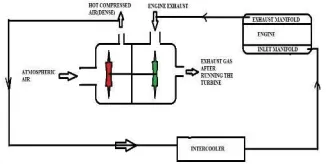
III. TURBOCHARGER WITH AFTERCOOLER (WATER)
Figure 2: Working Principle of conventional turbocharger in Diesel Locoengine
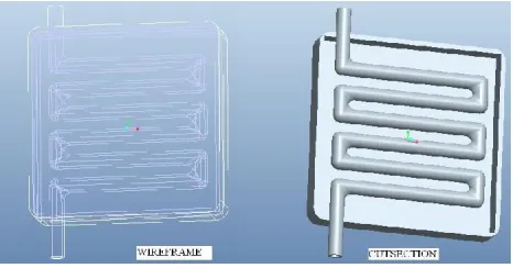
Figure 3: Modelling of after cooler in Pro-E
Figure 4: Flow pattern of after cooler (Solid works)
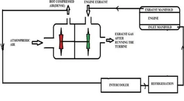
IV. TURBOCHARGING SYSTEM WITH AIR CONDITIONER ASSISTED INTERCOOLER
Figure 5: Aftercooler with refrigerator assisted
In this system the air conditioning system is used to assist the turbocharging system. In summers, when the efficiency of the intercooler is low due to high ambient temperature, the air conditioning system will be used to improve its efficiency because in summers, normally the AC is always switched on while we drive and on the other hand, we don’t need this system in winters because the ambient temperature is sufficiently cool to improve the efficiency of the intercooler. So the design of the intercooler is such that it will work properly with and without the air conditioning system (i.e. in summers and winters both). Besides this it will also increase the charge density to high extent. This will increase the oxygen availability in the cylinder for combustion.
evaporated by absorbing the required latent heat. This cools the hot compressed air flowing in the tubes of intercooler coming from the turbocharger compressor.
Figure 6: Modelling of refrigerator cooler Figure 7: Analysis of refrigerator cooler
VI. COMPARISON OF OXYGEN CONTENT
6.1 Calculations for the percentage increase in the mass of oxygen entering into intake manifold of the engine.
When the air enters into intake manifold of the engine through normal air cooled intercooler. Taking average of all
readings of temperature of air at the inlet and outlet of the intercooler, we have T1=110 oC and T2=82.22 oC
Now from equation 3, we have
Percentage increase in the mass of oxygen =100(1−T2/T1)/(T2/T1)
=100(1−82.22/110)/(82.22/110) = 33.7793%
6.2 Calculations for the percentage increase in the mass of oxygen entering into intake manifold of the engine. When the air enters into intake manifold of the engine through specially designed refrigerated and air cooled intercooler. Taking average of all readings of temperature of air at the inlet and outlet of the intercooler, we have
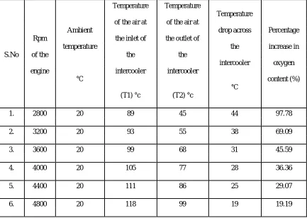
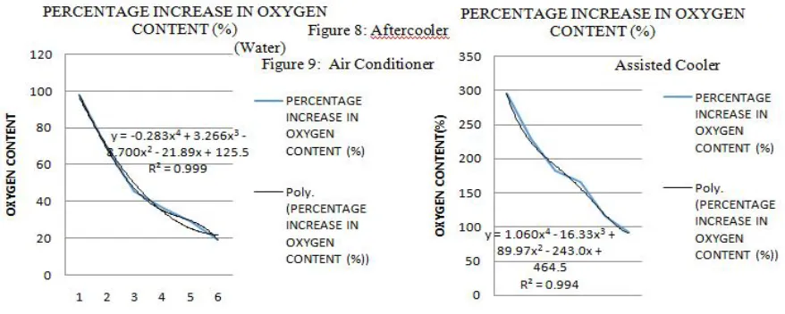
Table 1: Aftercooler (Water)
Temperature Temperature
Temperature
of the air at of the air at
Ambient drop across Percentage
Rpm the inlet of the outlet of
temperature the increase in
S.No of the the the
intercooler oxygen
engine intercooler intercooler
°C content (%)
(T1) °c (T2) °c
°C
1. 2800 20 89 45 44 97.78
2. 3200 20 93 55 38 69.09
3. 3600 20 99 68 31 45.59
4. 4000 20 105 77 28 36.36
5. 4400 20 111 86 25 29.07
6. 4800 20 118 99 19 19.19
Regression Equation:
Table 2: Air Conditioner Assisted Intercooler
Temperature Temperature
Temperature
Ambient of the air at the of the air at the Percentage
Rpm of drop across the
temperature inlet of the outlet of the increase in
S.No the intercooler
intercooler intercooler oxygen
engine
°C content (%)
°C
(T1) °c (T2) °c
1. 2800 19 87 22 65 295.46
2. 3200 19 92 28 64 228.58
3. 3600 19 96 34 62 182.35
4. 4000 19 101 38 63 165.79
5. 4400 19 110 51 59 115.68
6. 4800 19 119 62 57 91.94
Regression Equation:
VII. CONCLUSION
From the above collected data and calculations, it is being concluded that when normal air cooled intercooler is used to cool down the hot air before entering into the engine cylinder, the mass of oxygen being fed to the engine becomes 1.43 times but when refrigerated intercooler is used, it becomes 2.618 times. Increasing the oxygen content with the air leads to faster burn rates and the ability to control exhaust emissions. Added oxygen in the combustion air offers more potential for burning diesel. In future work, we are going to create an Artificial Neural Network for the above results that are generated from analysis report.
REFERENCES
[1] Flynn, P.F.:”Turbocharging Four-Cycle Diesel Engines” SAE paper 790314, SAE trans., vol. 88, 1979.
[2] Watson, N., and Janota, M.S.: Turbocharging the Internal Combustion Engine, Wiley-Interscience Publications, John Wiley, New York, 1982.
[3] Gyssler, G.: “Problems Associated with Turbocharging Large Two-Stroke Diesel Engines” Proc. CIMAC, paper B.16, 1965. [4] Bhinder, F.S.:”Supercharging Compressors-Problems and Potentials of the Various Alternatives,” SAE paper 840243, 1984. [5] John B. Heywood, “Internal Combustion Engine Fundamentals”, McGraw-Hill series in mechanical engineering.
[6] Magdi S. Mahmoud,”Improved Controller Design for Turbocharged Diesel Engine”, Proceedings ofthe World Congress on Engineering
2012 Vol III WCE 2012, July 4 - 6, 2012, London, U.K.