An Efficient Dynamic Approach for Exact
Reconstruction for CT Image Application
S.Asif Hussain, P.Syamala devi, C.Hemanth
Department of ECE, A.I.T.S, Rajampet, Andhra Pradesh, India
Abstract— For reconstructing volume of filtered projection data a parallel computing algorithm is proposed which suits spiral cone beam CT access for improvement of speed with high end processor. This work uses phantom data to achieve higher speed by accessing memory many times here the work is carried frame by frame as the pixel data arrives from filtered back projection; Interpolation is used for dedicated volume data which is decided by the coordinates of neighborhood pixels. Image quality is achieved in real time to refine artifacts by using parallel computing algorithm, experiment results shows the reduction of memory accessing times from many to one.
Keywords- Filtered back projection, Parallel computing Spiral cone beam CT, Artifacts
IINTRODUCTION
Digital image reconstruction is a robust by means by which the underlying images hidden in blurry and noisy data can be reveled [14]. The main challenge is sensitivity to measure noise to the input data, which can be magnified strongly, resulting in large artifacts in the reconstructed image .Many imaging techniques are based on reconstructing an image from data that can be interpreted, either directly or after some preprocessing, as a set of projections of the imaged object. The mathematical foundation is provided by the Radon transform (RT) which computes 1-D projections of a 2-D data at different view angles. Different from X-ray radiograph, the inner structure of the FOV can be detected with CT, or the CT image has much better space resolution than tradition X-ray radiograph [14].
CT has gain widely use as a tool not only in medical as medical imaging, noninvasive diagnostics and surgical planning but also in industry for nondestructive inspection[15]. In CT imaging, for example, the data is obtained by passing a set of narrow X-ray beams through the scanned object and collecting their intensities using an array of sensors. The acquired data represents the Radon transform of the cross-sectional absorption densities that form the image [1]. Munson et al. [2] showed that the data collected by the SAR, after demodulation and low pass filtering, represents the Fourier transform of the projections obtained from the reflectivity density of the targeted ground patch.
X-ray computed tomography is a technique closely combined with the X-ray radiation. With the technique, the inner structure of an N dimensional object can be reconstructed from the N -1 dimensional projections [4] Different from X-ray radiograph, the inner structure of the FOV can be detected with CT, or the CT image has much better space resolution than tradition X-ray radiograph[12].
However most popular in practice are methods based on the back projection (BP) operation which reduces the distortion by avoiding the interpolation step. The approach is also more suitable to handle other problems such as wave front curvature effects in SAR imaging the image reconstruction algorithm for the spiral cone beam CT can be divided into two categories, the approximate and the exact. Typically, the former one contains various kinds of the FDK-type algorithm transformed from the classic FDK-algorithm for circular cone beam CT which is widely used in the clinic now a days . The advantage of the FDK algorithm includes its fast computing speed and good image quality. But the disadvantage is also obvious, that is the cone beam angle could not be too big, or the artifact becomes very serious. Nowadays, the spiral cone-beam CT is not only the mainstream for its really fast scanning speed and the ability to produce truly 3D image and [5,6]. In 2002, katsevich proposed the first theoretical exact reconstruction formula for spiral; cone beam CT [7,8]. It is of truly FBP type with one dimensional shift invariant filtering, as a result the computation is more efficient than the random transform based reconstruction algorithm .It has feature of solving the long object problem and uses the data inside the Tam-Danielson window[9] and some more outside the window. Though it’s numerous advantages, the bottle neck is still obvious for its intensive computation. After the formula came out, several numerical study and implementation for the formula has been reported
In 2007, Jiang proposed a fast algorithm for katsevichs formula, the cone beam cover method [10] different from the pi –line method; the new method adopts the new concept cone beam cover. The method can update the voxel defined in the cone beam cover for each projection frame, so a parallel computing can be achieved .then, and then implement the new method with a Linux cluster [12] .Each frame occupies a computation node
In this paper, we focus the back projection (BP) operation the computational bottle neck [13] of the FBP algorithm.
II . BACKGROUND
p in F O c c tr
o
c
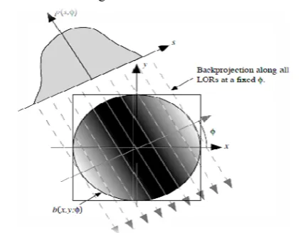
p a th o w is s w to n c A O p n th o f υ o th W p th in F im f f projection step nto all elemenFig 1. Back pr array o
One might as collected proje case due to th
ransform. In O
of the Fourie
center and le
perform back and examine t he contributio one contributi way of unders s with the for simply back p would be heav o the entire L needs to be re contributions tA. filtered-ba
Our goal is to projection, the needs to be
hroughout the of the back pr filter
υ=
of the Fourier he Fourier spa
F ( ,
Where B ( projected imag
he back proj nverse Fourie F(x,y) This is
mage reconst first back proj filter, and then
p, the best we nts along the L
rojection b(x,y f all values P(
ssume that str ections will re he oversampl Other words, e
er space res
ess
sampling projections at the Fourier tr on at the orig ion at the edg standing this o rward projecti project the po vily blurred sin LOR from wh e-weighted, or throughout theck projection
o compute f ( e oversamplin filtered in e Fourier spac
rojected imag
this cone fil space and de ace. This oper
, , is the 2 ge and F( ,
jection-filtere er transform
known as th truction metho
jected, filtere n inverse Four
e can do is pl LOR.
y,Ø), into an i (S,Ø) for a fix
raight back p eturn the Imag ling in the ce each
projectio
sulting in ov
at the edges. t only two an ransform of th gin is doubled ges of the fie oversampling ion of a single oint source pr
nce the projec hich they cam r ‘filtered’, in e field of view
(fbp) reconst
(x, y) from p ng in the cen
order to ha e. Basically, t ge must be fi
ter accentuate accentuates v ration is summ
2-d Fourier tr
is the 2-D d image. Th
of F( , t
he back proje od, where the
d in Fourier rier transform
lace a constan
image reconst xed value of Ø
projection of ge, but this is enter of the
on fills in on
versampling
For example gles, say Ø1 he result we s d while there eld of view. Ain the space e point source rojections, the ctions are adde e. The oversa n order to hav w
truction
p(s, Ø) . Afte nter of Fourie
ave equal sa the Fourier tra iltered with a
es values at th values at the ce marized in
ansform of th Fourier transf he final step
to obtain the ction-filtering e projection d space with th med. Alternativ nt value ruction Ø all the not the Fourier
ne slice
in the
e, if we and Ø2 see that is only Another domain e. If we e image ed back ampling ve equal er back r space ampling ansform a ‘cone’ he edge enter of he back form of is the e image g (BPF) data are he cone vely the filt of tha to gra Th usi for int dis B. If pro (FB W Ca Fo | dim filt fin filt vie cal can pa A. Th int an F W Th Sin (FB Ba f(x He tra pro Th |ωrB. In dis an the [0,
tering can be f b(x, y) with at the function
the convolu adually decay hus any nume ing a signific r the final re terchanging t scussed next.
Reconstruct
we intercha ojection steps BP) image rec F(x, y) = here the 'filter
an be regarded ourier transfor
| is a sectio mensional con ter is applied nite support i tered projectio ew. This mean lculated with n be used with art of the reaso
FILTERED
he Radon tran tegral project ngles θ. The co
,
here r and θ a he projections nograms. In BP) algorithm ased on the we
x,y)= ,
( ,
ere
ansform in th ojection opera
F(x,y) = β
he projections r| and then bac
DISCRETE
n practice, the stribution are nd the reconstr e projection a , π) and that
performed in
h A d
n b(x, y) has a ution with the ying values o
erical proced antly larger im esult. This di the filtering
tion by filtere
ange the ord ,we obtain th construction m
, Ø
red' projection
,
d as pre-corre rm of f(x,y). T
on through th ne filter. An ad d to each me in s, and we
ons for | | le ns that with F
a much sma h BPF, for the on for the popu
III. M
BACKPROJE
nsform (RT) tions of a 2-ontinuous Rad
,
are polar coord s ˆ f(r, θ) are
their original ms are
ell-known inv
,
| | (r
,
he variable r, ator
,
s f(r, θ) are fi ck projected t
DIRECT BA
e number of determined b ructed image angles θ are e all images ar
image space disadvantage o
a larger suppo e filter term outside the su dure must firs mage matrix isadvantage c
and back p
ed-back projec
der of the f he Useful filter method:
n, given by
| |
ected for the o The one dimen
he rotationall dvantage of F easured projec
only need to ss than the ra FBP the image
aller reconstru e same level o ularity of the F
METHODS ECTION ALG
represents a D function f don transform
dinates and δ
e also referred l form, filtere
version formul
r, ).
, represen and B is th
irst filtered us to reconstruct
CK PROJEC
projections P by the data ac is discrete. W evenly distribu e square with
via the convo of this approa ort than f (x, y , which resu upport of f (x st compute b size than is n can be avoide projection step ction (FBP) filtering and red-back proje
,
oversampling nsional 'ramp ly symmetric FBP is that the ction, which o back projec adius of the fie can be effic uction matrix of accuracy. T FBP algorithm
GORITHMS
set of paralle f(x, y) at dif is defined by
is the unit im d to as the da ed back proje
la for the RT:
nts a 1-D F he continuous
sing the ramp
the image.
CTION.
P and the sam cquiring equip We will assum uted in the in h N × N pixe
olution ach is y) due ults in
im p w p o
F
I r a a m o k
A
T H c p
W o T
N w T d
mplement th projection ope windowed an performed for over all angles
F (m, n) = ∑ (
nterpolation w required to com approximation achieved by model the phy our implemen kernel.
IV. PRACT A. THE SPIR
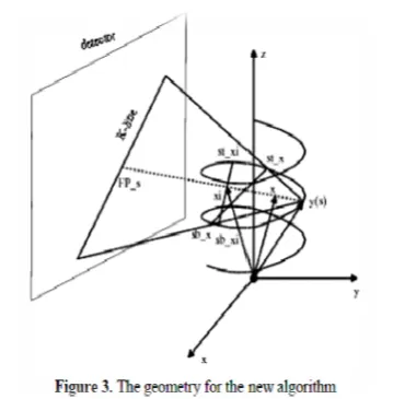
Figure The geometry Here, is t coordinate sy position which
Where s is the of the support Then, the unit
Now, a rotatin with its two ax To the detecto detector plane,
e FBP algor eration is dis nd sampled. T
each pixel f(m s θ:
(mcos +nsin
with a kernel mpute sample n to the con introducing t ysical propertie ntation, howe
TICAL RECO RAL CONE-B
1. The geome of the spiral c the voxel to b ystem O-XYZ h can be denot
cos .
e rotation ange cylinder. vector pointin
,
ng coordinate xis’s ̂ and or plane while , defined by:̂ sin
̂ cos
̂
rithm on a c scretized and The discrete m, n) as a sum
, θ). l φ (ρ) in th ed at non-in ntinuous back
the image sa es of the sensi ever, we use
ONSTRUCTI BEAM CT G
etry of spiral c cone-beam CT be reconstruct
Z. Denotes
ted as
. sin ,
el of the sourc
ng from (S)
is adopted at d parallel
the axis ˆw e
n , cos ,
s , sin
0,0, 1
computer, th d the ramp f
back projec m of projected
he radial direc ntegral values k projection ampling oper ing equipment
the ideal sa
ION APPRO GEOMETRY
cone beam CT T is shown in ted. In the Ca s the X-ray
ce and R is the
to is :
t source positi
e perpendicula
, 0
, 0
he back filter is ction is d values
ction is s. Better
can be rator to t [3]. In ampling
OACH
T n Fig. 1.
artesian source
e radius
ion y(s)
ar to the On ori pla the
B.
Pa Le
Ob po Fo
Th F(
H we ex f(
As co the
δf( Ac the Pa ho
δf( e
n the detecto
igin at the pr ane and the tw e detector plan
Proposed al
arallel back pr et’s make the f
Df
bviously, s F osition s . Furth ollowing defin
f( =
hen,
Here is the -e can s-e-e tha
ists a δf( . w is updated a
s shown in F nnecting sour e following eq (
ccording to th e projection no arametric in olds
(
0
lse
or plane, a th rojection of th wo axis’s para ne is expanded
lgorithm:
rojection following defi
f( (s), ,
FP is the filt hermore, let’s nition: F
- line decided at for each so we say that
at source posi
Fig. 3., let rce s and voxe quation holds: he sufficient co
ot at the sourc nterval to be
0 ,
hird coordina he X-ray sour allel to . ̂ an d by the two v
finition
tered projecti s make the
… by the voxel ource position
tions s by δf(
to be the el . Obviou
ondition of π
ce on the 0.Then, the
if s
ate is defined rce on the de nd In this vectors
.
ion data at s
…….δf( .
ns s on the
.
voxels on th usly,
-line, we can
following equ d with etector
s way,
source
there
he ray
make
This indicates that if the projection data of a ray is given, then all the voxels on the ray can be updated.
Here, we define the voxels on a ray to be:
X= , ,
Where connects sourse s and projection F . so X is the set of the voxels on
Now
Δf(x)=
Then the exact reconstruction formula can be expressed as:
f(X) = +……δ f(x ) =
Eqn.updates the voxels on the ray connecting source s and projection F If we define FP to
be the set of all the projection at source s , s Ray to be all the ray pass Ra . to be all the voxels on
s Ray . Then we come to the parallel reconstruction formula:
F( … … .
We can see from the equation that the voxels in s X can be updated if one frame of filtered projection arrives. When the next frame of filtered projection arrives, another set of s X can be updated.
The voxel to be updated has the following features: (1) The voxel is in the support cylinder
(2) the source s is on the parametic interval decided by voxel
V. THE EXACT RECONSTRUCTION FORMULA The exact formula proposed by Katsevich can be expressed as following:
f( =- , dγ
Here Df( , is the projection of the reconstructed object . is the π parametric interval.
From the equation we can see that the projection data is first filtered, then the filtered projection data is Back projected to form the attenuation image. It’s of truly FBP type.
The formula can be solved by the following five steps: (1) Derive the projection data Df(y,θ) using chain rule
, , , , ,
1
(2) Length weight correction
, , (s,u,w)
(3) Rebinning
Define r to be the maximum[15] radius of the object arcsin(r/R), using linear interpolation to all the
[ -π/2- ,
, , , , ,
Here , = (Ψ+ )
(4) IDfiltering
, , = , , ,
(5) Rebinning
, , , , ,
Here , is th one with the least resolution value ,
satisfyig
).
(6) BACK PROJECTION
f(
x
, ,,ds
VI.SIMULATIONRESULTS
Fig1:Shows the CT image
Fig 2:The sinogram image acquired from CT
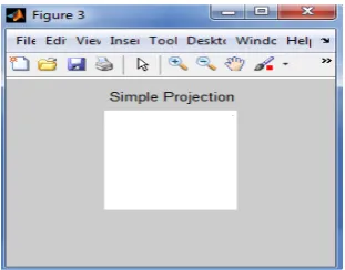
Fig 3 : The simple projection image
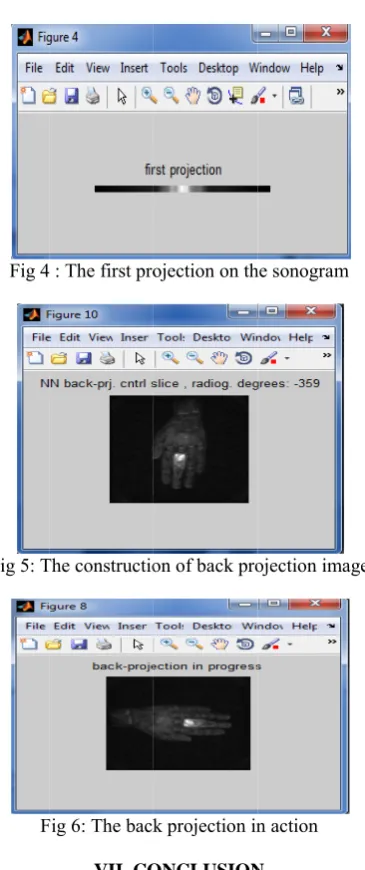
T s c m th th d u p e r m r a w m a g Fig 4
Fig 5: T
F
The implemen spiral cone-bea computation. memory is qui
his paper, we hat can reduce down to once updated once pipeline can b experiment re reconstructed method may researchers int algorithms in works to be do more interpola and find some greatly reduce
4 : The first pro
The constructio
Fig 6: The back
VII. CO ntation of the
am CT is quit Among them ite a bottle nec e propose a p
e the memory e. As some c
a filtered b be achieved esults, we c by the new a provide som tending to im
hardware. T one. The most
ation methods e new paralle
d if proper int
ojection on th
on of back pro
k projection in
ONCLUSION exact reconstr te time consum m, the frequ
ck to improve parallel back y accessing tim
certain attenu back projecti for the recon an see that algorithm is sa me suggestion mplement the
Though, ther t important on s for the filte l algorithm a terpolation can he sonogram ojection image n action N ruction algorit ming for its in uent access e the performa projection alg mes from man
uation value ion data arr nstruction. Fr the image atisfactory. T ns to engine
exact reconst e are some ne is to develo
ered projectio as the artifact n be employed
e thm for ntensive of the ance. In gorithm ny times can be rives, a rom the quality The new eers or truction further op some on data, can be d. Th De the [1] [2] [3] [4] [5] [6] [7] [8] [9] [10 [11 [12 [13 [14 [15
his work was elhi at AITS , e successful co
F. Natterer, The
Wiley, 1986. D. C. Munson, J
of spotlight-m vol. 71, pp. 91 S. Basu and
reconstruction
Processing, vo G. T. Herman Academic Pre Kalender, W. A
and Biology, v Kalender, W. A. with single-bre scanner rotatio Katsevich, A. Inversion Alg Mathematics, Katsevich, A., “ spiral compute 32, no. 4, pp. 6 Danielsson, P. E
exact reconstru new detector Proceedings o Radiology and 0] Yang, J., Kon method: An exact algorithm and Technolog 1] Yang, J., G Implementatio Biomedical Im 2] Michael, G., “ 36, no. 6, pp. 4 3] S. Asif Hussai
Medical image Vol 5, No.3 (2 4] Michael, G., “ 36, no. 6, pp. 4 5] Hiriyannaiah,
Imaging”, IEE 1997.
include Signal P
papers in Nation Professional soc IAENG (Hongk Signal Processin ACKNOW supported by ,Rajampet and ompletion of m
REFE
e Mathematics of
J. D. O’Brien, an mode synthetic ap 17–925, August 1 Y. Bresler, “O n algorithm for ol. 9, pp. 1760–17 n, Image recons
ss, 1980. A., “X-ray compu vol. 51, no.13, pp
., Seissler, W., K eath-hold techniq on”, Radiology, v ., “Theoretically gorithm For Sp vol. 62, no. 6, pp “An improved ex ed tomography”, 681-697, 2004.
E., Edholm, P., uction for helical arrangement an of the Meeting d Nuclear Medicin ng, Q., Zhou, T.,
approach to per m for spiral con gy, vol. 12, no. 4, Guo, X., Kong,
on of Katsevich's maging”, vol. 200 “X-ray computed 442-451, 2001. in and Dr. M.N.
e modeling with d 2012) PP. 213-217 “X-ray computed 442-451, 2001.
H. P., “X-ray EE Signal Process
Chennakesavula Electronics.& C Ananthapur, In Institute of Tech Dept. of ECE an Processing, Time Se
Asif Hussian Electronics University, towards PhD JNTU Unive Annamachar Rajampet, A Professor in nal & International cieties like ISTE ( kong) and WASE ng, Time Series Ana
WLEDGMENT RPS scheme d special than
my work RENCES
f Computerized T
nd J. W. K., “A to perture radar,” Pr
983.
O(N2 log2 N) tomography,” IE
772, October 200
truction from p
uted tomography p. 29-43, 2006. Klotz, E., Vock, P
que, continuous tr vol. 176, no.1, pp y Exact Filtered piral CT”, SIAM p. 2012-2026, 200 xact filtered backp
Advances in Ap
Eriksson, J., Ma l cone-beam scan nd a new comp on Fully 3D Im ne, pp. 141-144, , Jiang, M., (200 rforming backpro e beam CT”, Jou , pp. 199-214, 20
Q., Zhou, T., FBP Algorithm. 06, pp. 1-8, 2006. d tomography”, P
Giri Prasad, Dr, dynamic image r 7
d tomography”, P
y computed Tom sing Magazine, v
AUTHORS P
a Hemanth recei Communication Eng ndia. Presently he hnology & Science nd pursuing his M.T eries Analysis and Im
n. Shaik received B & Communicati Hyderabad, India. D Degree in Biome ersity, Anantapur, rya Institute of A.P., India. He n Dept. of ECE. H l Conferences & jo (India), BMESI (In E (Hongkong).His alysis and Image Pr
T
of A.I.C.T.E nks to my guid
Tomography.New
omographic form
roceedingsof the
filtered backpro
IEEE Trans. on
00.
projections. New
y”, Physics in M
., “Spiral volume ransport, and con .181-183, 1970. d Backprojectio M Journal on A 02.
projection algorit pplied Mathemati
agnusson, M., “T nning of long obj pleteness conditio mage Reconstruc
1997.
04), “Cone beam ojection in Kats urnal of X-Ray S 04.
, Jiang, M., “P International Jou
Physical Educatio
D. Satya Naraya econstruction “in
Physical Educatio
mography for M vol. 14, no. 2, pp.
PROFILE
ived B.Tech Deg gg. from J.N.T.Un e is with Annam es, Rajampet, A.P., Tech. His research mage Processing.
B.Tech & M.Tech D ion Engg. from
He is currently edical Image Proce India. Presently he Technology & S is working as A e presented many ournals. He is a me ndia), IACSIT (Sin research interests ocessing. , New de for w York: mulation
e IEEE,