Scholarship@Western
Scholarship@Western
Electronic Thesis and Dissertation Repository
6-21-2012 12:00 AM
Experimental Evaluation of the Projection-based Force Reflection
Experimental Evaluation of the Projection-based Force Reflection
Algorithms for Haptic Interaction with Virtual Environment
Algorithms for Haptic Interaction with Virtual Environment
Mir Z. Hasan
The University of Western Ontario Supervisor
Dr. Ilia G. Polushin
The University of Western Ontario
Graduate Program in Electrical and Computer Engineering
A thesis submitted in partial fulfillment of the requirements for the degree in Master of Engineering Science
© Mir Z. Hasan 2012
Follow this and additional works at: https://ir.lib.uwo.ca/etd
Part of the Controls and Control Theory Commons
Recommended Citation Recommended Citation
Hasan, Mir Z., "Experimental Evaluation of the Projection-based Force Reflection Algorithms for Haptic Interaction with Virtual Environment" (2012). Electronic Thesis and Dissertation Repository. 598.
https://ir.lib.uwo.ca/etd/598
This Dissertation/Thesis is brought to you for free and open access by Scholarship@Western. It has been accepted for inclusion in Electronic Thesis and Dissertation Repository by an authorized administrator of
EXPERIMENTAL EVALUATION OF THE PROJECTION-BASED
FORCE REFLECTION ALGORITHMS FOR HAPTIC INTERACTION
WITH VIRTUAL ENVIRONMENT
(Spine title: Experimental Evaluation of the PFRA for Haptic Interfaces)
(Thesis format: Monograph)
by
Mir Zayed Hasan
Graduate Program in Electrical and Computer Engineering
A thesis submitted in partial fulfillment
of the requirements for the degree of
Master of Engineering Science
The School of Graduate and Postdoctoral Studies
The University of Western Ontario
London, Ontario, Canada
c
CERTIFICATE OF EXAMINATION
Supervisor:
. . . . Dr. I. Polushin
Supervisory Committee:
Examiners:
. . . . Dr. R. V. Patel
. . . . Dr. Q. M. Rahman
. . . . Dr. O. R. Tutunea-Fatan
The thesis by
Mir Zayed Hasan
entitled:
Experimental Evaluation of the Projection-based Force Reflection Algorithms for Haptic Interaction with Virtual Environment
is accepted in partial fulfilment of the requirements for the degree of Master of Engineering Science
. . . . Date
. . . .
Chair of the Thesis Examination Board
Abstract
Haptic interaction with virtual environments is currently a major and growing area of research with a number of emerging applications, particularly in the field of robotics. Dig-ital implementation of the virtual environments, however, introduces errors which may result in instability of the haptic displays. This thesis deals with experimental investigation of the Projection-Based Force Reflection Algorithms (PFRAs) for haptic interaction with virtual environments, focusing on their performance in terms of stability and transparency. Experiments were performed to compare the PFRA in terms of performance for both non-delayed and non-delayed haptic interactions with more conventional haptic rendering methods, such as the Virtual Coupling (VC) and Wave Variables (WV). The results demonstrated that the PFRA is more stable, guarantees higher levels of transparency, and is less sensitive to decrease in update rates.
Keywords:Haptic Systems, Projection based Force Reflection Algorithm
I would like to express my sincere appreciation and gratitude to my supervisor, Dr. Ilia G. Polushin, Assistant Professor, Department of Electrical and Computer Engineering, West-ern University, for his guidance, advice, assistance and encouragement throughout my re-search work.
I would like to express my thanks to Mr. Amir Takhmar, PhD student, Department of Elec-trical and Computer Engineering, Western University, for his assistance in modelling the haptic device. I would also like to extend my thanks to my friends in the Robotics and Control Laboratory for their help throughout the time I worked on my research.
I am especially grateful to my wife, Mrs. Qamrun Nahar, for her moral support and en-couragement during the work.
Finally, I would like to express my gratitude to my parents, Mr. Mir Moazzem Hossain and Mrs. Mahbuba Morshed, for their love and support throughout my life.
Contents
Certificate of Examination ii
Abstract iii
List of Figures viii
List of Tables x
List of Acronyms xi
1 Introduction 1
1.1 Introduction . . . 1
1.2 Haptics . . . 2
1.2.1 Architecture of Virtual Reality Simulation . . . 3
1.2.2 Haptic Interface Devices . . . 4
1.2.3 Haptic Rendering Algorithms . . . 5
1.2.4 Application Areas of Haptics . . . 8
1.3 Literature Survey . . . 10
1.3.1 Virtual Coupling . . . 10
1.3.2 Design of Haptic Devices . . . 14
1.3.3 Virtual Environments and Haptic Systems . . . 15
1.3.4 Haptic Systems with Time Delay . . . 17
1.3.5 Wave Variables and Haptics . . . 19
1.3.6 Projection Based Force Reflection Algorithm . . . 21
1.4 Objectives of the Thesis . . . 22
1.5 Contributions of the Thesis . . . 22
1.6 Outline of the Thesis . . . 23
2 Haptic Systems: Stability Issues 24 2.1 Introduction . . . 24
2.2 Virtual Walls . . . 24
2.2.1 Passivity of Virtual Walls . . . 25
2.3 Z-width . . . 27
2.4 Virtual Coupling . . . 29
2.7 Conclusion . . . 34
3 Problem Formulation and Experimental Setup 36 3.1 Introduction . . . 36
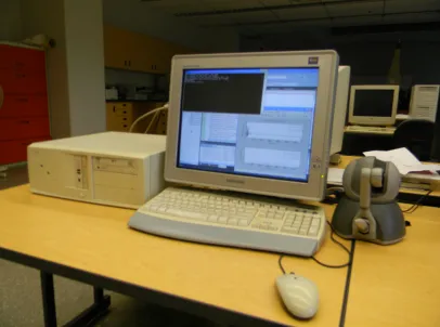
3.2 Experimental Setup . . . 37
3.3 Virtual Coupling . . . 39
3.4 Wave Variables . . . 40
3.5 Impedance Matching . . . 42
3.6 Projection based Force Reflection Algorithm . . . 44
3.7 Apparent Stiffness . . . 45
3.8 Conclusion . . . 45
4 Haptic Interaction without Communication Delays 48 4.1 Introduction . . . 48
4.2 Experiment 1: Virtual Wall Stiffness . . . 48
4.3 Experiment 2: Update Rates . . . 50
4.4 Experiment 3: PFRA Parameterα . . . 52
4.5 Experiment 4: Transparency . . . 54
4.6 Conclusion . . . 55
5 Haptic Interaction with Communication Delays 62 5.1 Introduction . . . 62
5.2 Delay Pattern . . . 62
5.3 Experiment 1: Virtual Wall Stiffness . . . 64
5.4 Experiment 2: Update Rates . . . 71
5.5 Experiment 3: Delay . . . 78
5.6 Experiment 4: PFRA Parameterα . . . 83
5.7 Experiment 5: Delay Variation . . . 83
5.8 Experiment 6: Apparent Stiffness . . . 86
5.9 Conclusion . . . 89
6 Discussion 90 6.1 Introduction . . . 90
6.2 Conclusions Drawn from the Work . . . 91
6.2.1 Non-Delayed Haptic Interaction . . . 91
6.2.2 Delayed Haptic Interaction . . . 93
6.3 Future Work . . . 95
Bibliography 97
A Dirty Derivative Filter 106
B High Gain Observer 107
C Model of the Phantom OmniTMHaptic Device 109
Curriculum Vitae 112
1.1 Virtual Reality Application Architecture . . . 4
1.2 Haptic Interface Devices . . . 5
1.3 Haptic Rendering Algorithm . . . 6
1.4 1DOF Interaction . . . 7
2.1 Block Diagram of a Implementation of Virtual Wall . . . 25
2.2 Virtual Coupling . . . 30
2.3 Wave Transformation . . . 31
2.4 Interface between wave variables and power variables . . . 32
2.5 Decomposition of reflected forces . . . 34
3.1 Experimental Setup . . . 38
3.2 Flowchart of Virtual Coupling Technique . . . 41
3.3 Flowchart of Wave Variables Technique . . . 43
3.4 Impedance Matching Technique [1] . . . 44
3.5 Flowchart of Force Reflection Technique . . . 46
4.1 Reflected force forKw =3N/mm . . . 50
4.2 Reflected force forKw =10N/mm . . . 51
4.3 Position Information forKw =3N/mm . . . 52
4.4 Position Information forKw =10N/mm . . . 53
4.5 Reflected Force for PFRA for different update rates . . . 54
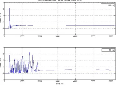
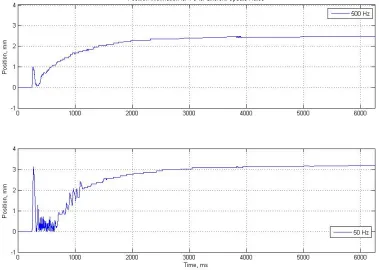
4.6 Position Information for PFRA for different update rates . . . 55
4.7 Reflected Force for DFR for different update rates . . . 56
4.8 Position Information for DFR for different update rates . . . 57
4.9 Reflected Force for VC for different update rates . . . 58
4.10 Position Information for VC for different update rates . . . 59
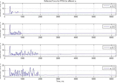
4.11 Reflected force for different values ofα . . . 60
4.12 Position for different values ofα . . . 61
5.1 Pattern of Delay used . . . 63
5.2 Wave Variable: Stiffness and Reflected Force . . . 65
5.3 Wave Variable: Stiffness and Position . . . 66
5.4 PFRA: Stiffness and Reflected Force . . . 67
5.5 PFRA: Stiffness and Position . . . 68
5.6 DFR: Stiffness and Reflected Force . . . 69
5.7 DFR: Stiffness and Position . . . 70
5.8 WV: Update Rates and Reflected Force . . . 72
5.9 WV: Update Rates and Position . . . 73
5.10 PFRA: Update Rates and Reflected Force . . . 74
5.11 PFRA: Update Rates and Position . . . 75
5.12 DFR: Update Rates and Reflected Force . . . 76
5.13 DFR: Update Rates and Position . . . 77
5.14 Reflected Force for 100 ms . . . 79
5.15 Reflected Force for 500 ms . . . 80
5.16 Position Information for 100 ms . . . 81
5.17 Position Information for 500 ms . . . 82
5.18 Reflected Force forα . . . 84
5.19 Position Information forα . . . 85
5.20 Apparent Stiffness for 200 ms . . . 87
5.21 Apparent Stiffness for 500 ms . . . 88
C.1 Phantom Omni from SensAble Inc. [2] . . . 109
4.1 Actual and Apparent Stiffness for Non-delayed Case . . . 57
5.1 Apparent Stiffness for Delay Variations . . . 86 5.2 Actual and Apparent Stiffness . . . 87
List of Acronyms
PFRA: Projection based Force Reflection Algorithm DFR: Direct Force Reflection
VC: Virtual Coupling WV: Wave Variables DOF: Degree of Freedom
Introduction
1.1
Introduction
According to Robot Institute of America (RIA), the official definition of a robot is as fol-lows [3]:
A robot is a reprogrammable manipulator designed to move materials, parts, tools, or
spe-cialized devices through variable programmed motion for the performance of a variety of
tasks.
However, in the current context of robotics, this definition, while representing several
in-herent qualities of a robot, has become severely restricted. A robot can now be remotely
controlled to perform exploration in undersea environments and in space, conveys
infor-mation about a remote location to a user and can be used as a tool to perform surgical
operations. Telerobotics has revolutionized the applicability of robots in a wide variety of
fields. One of the major requirements of a telerobot is to convey information about the
nature (texture, stiffness, color, temperature, etc.) of a remote environment to the user.
The human sense organs accept information about the surrounding environment for
pro-cessing by the brain. In a similar manner, visual, auditory, haptic, olfactory and gustatory
Chapter1. Introduction 2
displays provide means of interaction between humans and virtual environments created by
a computer system. While focus has been primarily on developing visual and auditory
dis-plays, haptics has the potential to improve the human-computer interaction by introducing
the sense of touch. In the last decade, haptics has found application in molecular docking,
manipulation of nano-materials, surgical training, virtual prototyping, and digital sculpting,
among other areas. Haptics has enabled the active exploration of the virtual world [4].
1.2
Haptics
Haptics originates from the Greek word haptikos, which means ‘to grasp’or ‘perceive’,
and was coined by psychophysicists to label the subfield of their study in human touch
based perception and manipulation. Since the 1970s, in the field of robotics, it refers to
the modality of touch and may include sense of heat and surface texture of an object.
Hap-tic perception ranges from minor interactions in everyday life to social communications.
Researchers in the field of haptics are engaged in the development of devices and
associ-ated software that allow users to sense and interact with three dimensional objects rendered
in the virtual environment. Haptics can be used to improve the users’ experience during
interaction with the virtual environment in the following aspects [5]:
a) Improved usability;
b) Enhanced realism;
c) Restoration of mechanical feel.
The sense of touch can distinguish between surface structures. Although skin is the most
sensitive organ, additional receptors for haptic perception are located within muscles and
joints. These receptors provide kinaesthetic perception while those located on the skin
provide tactile perception. Tactile receptors can perceive forces with magnitudes in the
range from 5mN to 5N, detect surface textures with small variations from 1µm to 1mm,
can detect much larger forces with frequencies usually not higher than 10Hz [6]. The
combination of the responses from these two types of receptors allows humans to perform
coordinated movements and interact with their surrounding environment.
A wide variety of haptic devices have been designed based on their area of application and
the principle of operation. Force feedback techniques have received particular attention
from researchers. An alternative approach to force feedback is vibrotactile display where
multiple small forces are applied to the fingertips. Another technique to create a haptic
perception is to use a temperature display where both environmental temperature and the
sensation of heat or cold generated when grasping or colliding with an object can be
simu-lated. One more type of device is the 2D haptic device where 2DOF force feedback planar
device can be moved by the user to interact with edges of shapes in images.
1.2.1
Architecture of Virtual Reality Simulation
In order to simulate real or imaginary scenes that users can interact with, virtual reality
(VR) applications allow humans to use their senses to discern and experience different properties of the virtual environment. Usually a subset of these senses are used, typically
visual, auditory and touch are incorporated in such systems. A basic VR application has
the following elements [7]:
a) Simulation engine;
b) Visual, auditory and haptic rendering algorithms;
c) Transducers.
Haptic perception is achieved when the user holds or wears a haptic device, which
conveys information related to interaction with the virtual environment. While audio and
video feedback is unidirectional from the engine to the user, haptic communication is
Chapter1. Introduction 4
Figure 1.1: A basic architecture for virtual reality application incorporating audio, visual
and haptic feedback [7]
1.2.2
Haptic Interface Devices
Haptic interface devices typically behave like small robots that directly interact with the
human operator. They can be classified based on various features [7]:
a) Grounding locations, e.g. force feedback gloves and ground based devices;
b) Intrinsic mechanical behaviour: impedance and admittance;
c) Number of degree-of-freedom (DOF): number of possible dimensions of
move-ment or force exchange.
In order to successfully represent touch and generate haptic perception, all haptic devices
are expected to have the following desirable characteristics [7]:
a) Low back drive inertia;
b) Minimal constraints;
c) Symmetric inertia, friction, stiffness and frequency response;
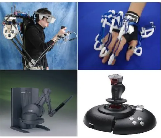
Figure 1.2: Examples of haptic interface devices currently in use and research (clockwise
from top left): Human exoskeleton [8], Haptic glove [9], Haptic joystick [10], and
Pen-based master [11]
1.2.3
Haptic Rendering Algorithms
The haptic interface is represented by an avatar in the virtual environment, and all
interac-tions with the environment are carried out by it. Contact between the avatar and the virtual
environment create action and reaction forces. These forces are computed by the haptic
rendering algorithms. Such an algorithm has the following components [7]:
a) Collision detection algorithms which detect collisions between the objects and the
avatar, also generating information about the location, the time and the extent of
the collision
b) Force-response algorithms generate the interaction force using the information
from the collision detection algorithm
c) Control algorithms minimize the error between the ideal and the actual forces
Chapter1. Introduction 6
Figure 1.3: The basic blocks of a haptic rendering algorithm [7]
a) The joint positions are obtained;
b) The avatar’s position is calculated by the forward kinematics algorithm;
c) The collision detection algorithm uses the position information to determine
col-lisions and the degree of penetration;
d) The forces between the avatar and virtual objects are calculated;
e) The calculated forces are then applied by the control algorithm though the haptic
device to the user while maintaining stability
While there is no fixed rule to determine the rate at which the force rendering
algo-rithms update the computation, a rate of 1kHz is common, as it allows the presentation of
reasonably complex objects with reasonably high stiffnesses. Two types of force rendering algorithms can be used [7]:
a) Geometry dependant force rendering algorithms: The interaction forces
geometry of the avatar. A simple version of this algorithm measures the position
of the operator and applies the forces to the operator along one spatial direction.
When rendering a virtual wall, due to the discrete nature of haptic interaction,
there will always be a penetration into the wall. This information can be used to
compute the interaction force. A simple algorithm to render the virtual wall using
this algorithm will be given by,
F =
0 x> xw
K(xw−x) x≤ xw
(1.1)
where, x describes the position of the avatar of the haptic device and xw is the
Figure 1.4: Virtual wall concept depicting a 1DOF interaction [7]
position of the virtual wall, andK ≥ 0 represents the stiffness of the wall.
More complex versions of this algorithm include algorithms to calculate forces in
2DOF as in the case of a mouse interacting with a PC, 3DOF interaction using the
point interaction paradigm, or more complex interactions with higher number of
Chapter1. Introduction 8
b) Surface property dependant force-rendering algorithms: The second type of
algo-rithms used to render forces in haptics utilizes information from tactile displays
and therefore are dependant on the nature of the surface of the object being
in-teracted with. Micro irregularities in the surface act as obstructions and cause
friction when two such surfaces come into contact. While the model of friction is
a complicated one, simpler, empirical models proposed by Leonardo da Vinci and
developed by Coulomb are used in 3DOF as a basis for simple frictional models
[7]. More accurate models exist, however, they typically require higher amount
of computations and may be unsuitable for real time implementation.
1.2.4
Application Areas of Haptics
a) Surgical Simulation and Medical Training: This is an important application
area for haptics. Haptic devices have found their use in training simulations for
palpation of subsurface liver tumours, echographic examination of human thigh,
for bone marrow harvest for transplant, for arthroscopic surgery, for simulation of
fluid filled objects to explain different surgical procedures, for simulation of organ motion, devices for surgical teleoperation, and in medical training simulators used
to gain baseline information about trainees.
b) Museum Displays: Using digital media and in-house kiosks, museums are
ex-ploring the possibility of creating 3D digital representations of their collections
that visitors can not only see but also touch to appreciate. This can also allow
cu-ratorial staffto interact with people at a remote location in joint tactile exploration of works of art.
c) Painting, Sculpting and CAD:Haptic Displays have been used as an alternative
input device for painting, sculpting, and CAD. Techniques have been developed
to study the texture of fabric, to aid visually impaired people in painting, to edit
d) Visualization: Scientific visualization has also benefited from incorporating
hap-tic systems. Haphap-tics and graphic displays have been combined in computation
software steering systems. Haptics have also been incorporated in software to
analyse chemical and biological molecular structures.
e) Military Applications: Aerospace and military training and simulation have also
taken advantage of developments in haptics. Force feedback gloves have been
used by workers at remote locations to simulate the reconfiguration of a vehicle
by handling different virtual components. NASA has been carrying out experi-ments in the psychophysical field to study the effects of attaching a 3DOF manip-ulandum to a visual display. Adding haptics to audio and visual display allows for
an increase in situation awareness, providing accurate orientation information in
land, sea and aerospace environments.
f) Interaction Techniques: Haptics has also been applied to user interface, where
force feedback can give the user a more realistic feeling of interacting with an
interface, such as pressing a button. Objects can be rendered with Javascript and
can be delivered for exploration using haptic mice via a standard webpage. Haptic
gloves have been used to provide users a more realistic feel of stacking or pushing
objects. Haptics have also been used by system designers to guide users along
a right path, by adding built-in force constraints along the wrong path or against
wrong choices.
g) Assistive Technology for Disabled Persons: Visually impaired people can
ben-efit from incorporating haptics in assistive technology. Computer user interfaces
have been haptically modified to identify edges of icons or windows. Software
have also been developed to aid people with such disabilities to identify objects
with simple shapes. Haptic displays have also been used to allow people to feel
the shape of mathematical curves or play simple games such as battleship. People
Chapter1. Introduction 10
rehabilitation program where movement exercises in virtual reality allow them to
move objects of defined size and weight from one place to the other.
1.3
Literature Survey
1.3.1
Virtual Coupling
When a unilateral constraint like a virtual wall is simulated, a demand is placed on the
requirements of the range of impedance that the haptic display can render, known as thez
-width, with the ideal dynamic range of it varying from near zero to near infinite. However,
such a wide range of impedances is not possible to simulate without the loss of stability.
Colgate, et. al., [12] proposed the concept of virtual coupling to overcome this problem. In
this work, the virtual tool and the environment are implemented in a way to guarantee that
they are discrete time passive. Specifically, the handle of the virtual tool is connected to
the handle of the haptic display via a multidimensional coupling consisting of stiffness and damping. The virtual coupling effectively limits the maximum impedance exhibited by the haptic display, even when the impedance of the virtual wall is infinite.
Adams and Hannaford [13, 14] extended the concept of virtual coupling from the impedance
model in [12] to the admittance model of haptic interaction. They represented the coupling
in the admittance display as a frequency dependent damper, which has a zero steady state
impedance, while an effective damping at high frequency created by the impedance of the mass that becomes dominant at those frequencies. Their analysis showed that the virtual
coupling network design is independent of the impedance or admittance causality of the
virtual environment model, if the environment is passive. They also showed that the two
port networks arising from the admittance and impedance displays are dual.
In [15, 16], the authors used Excalibur, a three degree of freedom Cartesian manipulator
simulation, to design stabilizing haptic interface control laws for a largez-width. They
im-plemented two variations of the virtual coupling: the impedance display and the admittance
display. Their experimental results showed that the impedance display is very simple but
not as adaptable as an admittance display.
Miller, et. al., [17] addressed the question of ensuring stability in nonpassive nonlinear
environments in both delayed and nondelayed form for haptic systems consisting of four
components: human, haptic device, virtual coupling and virtual environment. The authors
derived design conditions that guarantee the velocity signal from the device to the human
goes to zero in the steady state and all states are bounded. This would ensure that any
un-desirable velocity signal resulting from oscillatory motion can not be presented to the user.
They also considered a general device model that is exact.
Lertpolpairoj, et. al., [18] modified the concept of virtual coupling presented in [12]. The
authors adapted the values of stiffness and damping of the coupling depending on the pa-rameter called Interacting Frequency. Their experiments showed that the adaptive virtual
coupling was identical to the static virtual coupling for virtual environments with low stiff -ness values. But when the virtual environment has a high value of stiffness, the adaptive virtual coupling system represented the impedances better.
In [19], Lee and Lee presented a new model for stability analysis of the haptic device.
They modelled the human arm as a linear time-invariant (LTI) 2nd order impedance and a
response model. A nonlinear virtual coupling is developed to maximize the impedance of
the virtual coupling and to derive the stability condition. The stability condition proposed
by the authors is less conservative than the passivity condition. Their results showed that
the new stability condition increased the upper bound of achievable stiffness and damping compared to the passivity condition. When combined with a nonlinear version of virtual
coupling, the results proved even more satisfactory. In this case the authors designed the
Chapter1. Introduction 12
Bi, et.al. [20], used fuzzy logic to adapt the parameters of the virtual coupling in order
to improve its performance. Their results showed that the fuzzy logic based adaptive
vir-tual coupling produced very little overshoot in displacement when interacting with virvir-tual
environments, as compared to traditional virtual coupling. Also, the speed of response is
improved while maintaining the primary objective of stabilizing the a haptic display.
In [21], Akahane, et. al., used virtual coupling to interface between a virtual environment
and a High Definition Haptic Controller. The controller achieves a 10kHz high definition
haptic rendering in a 3DOF haptic interface, which has az-width almost ten times that of
a 1kHz rendering. An analytical method is used by the authors that allows for stable
ren-dering of a hard surface. For a Virtual Reality application to maintain a video rate control
frequency to provide visual sensation, the virtual environment is rendered at 60Hz. As the
haptic display is an impedance display rendered at 10kHz and the virtual environment is
an admittance display rendered at 60Hz, the authors used a virtual coupling process, for
up sampling and as an interface between the components. The system achieved stability of
the haptic system with a virtual coupling of low impedance while maintaining high fidelity
with the 10kHz high definition haptic rendering with a high interpolating impedance.
Questions on position coherency in network haptic virtual environment (NHVE) are
ad-dressed in [22]. The authors designed three virtual coupling schemes: two peer-to-peer and
one client-server model, to maintain position coherency. They did not use any time delay
compensation method. In the peer-to-peer schemes, a model of the mass is implemented at
each user, while the mass was modelled only at the server in the client-server model. When
there were only two users, the preliminary results presented by the authors showed that the
client-server model of the virtual coupling scheme had the lowest peak and RMS position
error. However, their analysis also showed that this model had the largest delay among the
three models. In [23], the authors carried out experiments using the three virtual coupling
schemes over the internet. Of the three experiments carried out, two used the same scheme
car-ried out using all three schemes for different transmission rates. Their results showed that peer-to-peer schemes were better at maintaining position coherency than the client server
model. An increase in delay time increased both the RMS position error and the peak
po-sition error for all schemes. The force values presented to the user also increased with a
decrease in the packet transmission rate. In [24], the authors compared the performance of
the virtual coupling schemes implemented on a NIST Net network emulator. This
emula-tion was carried out using delay times experienced in [23] between Seattle, Washington,
USA and Italy. The results showed that the performance of the emulator depends on the
transmission rate, where high values of transmission rates cause deviation from the results
obtained in [23].
In their paper, Bianchini, et. al.,[25] used Linear Matrix Inequality (LMI) to provide a
framework for stability analysis and virtual coupling design for multi-contact haptic
sys-tems. The LMI approach allowed for taking into account the structural constraints that arise
in a multi-contact scenario. As the system may be physically distributed, the virtual
cou-pling, which is often lumped together with the device, may share only limited information
with the device and the virtual environment due to decentralization and limited
communi-cation requirements. The authors proposed a design procedure for virtual coupling for such
a system which was two-fold: first, the levels of passivity to be displayed for guaranteed
stability by the virtual coupling and the device are computed, and then the structure of the
virtual coupling reflecting the constraints imposed on the system is implemented in a way
that allows the effects of the constraints on the realism of interaction can be qualitatively evaluated and tuned. In [26], the authors carried out experiments considering two cases,
one where a single operator is using two haptic devices and another where two operators
are operating two devices. When a perturbation is present in the environment, the virtual
coupling failed to provide stability in the first case, but was successful in the second case. In
[27], they expanded their experiments to consider M 1-DOF users not only distributed but
Chapter1. Introduction 14
to take into account the decentralization of the users. Using parameters similar to [26], the
proposed controller was able to stabilize the system with a non-zero solution.
ˇSurdilovi´c and Radoji´ci´c designed a robust control system to synthesize virtual coupling
for haptic interfaces interacting with a virtual environment in [28], which is an expansion
of the control theory developed for robot/environment interaction. The performance of the controller was demonstrated on a SISO admittance display. Experiments showed that the
interaction of the haptic device with virtual environment was stable, reaching both contact
transition stability and coupled stability. The authors carried out experiments showing that
a single set parameters for the virtual coupling results in a controller that is robust enough
for a wide range of stiffness values for the environment.
In order to improve transparency while maintaining stability in a haptic system with virtual
coupling, Zhu, et.al., in [29] attempted to find an equilibrium point between stability and
transparency by using the speed gain, position gain and the damping and the mass of the
vir-tual coupling to optimize the loop gains and the virvir-tual coupling impedance. This resulted
in a low-inertia high bandwidth haptic interface device which had guaranteed stability and
good transparency.
1.3.2
Design of Haptic Devices
A haptic interface is a device that uses mechanical actuators to reflect force back to the user
allowing him to touch, feel or manipulate a virtual environment. Adelstein and Rosen [30]
designed a two degree of freedom force reflecting manipulandum based on a 5R spherical
closed chain linkage joining the output of two DC motors to a handle operated by a user.
The motivation of their design was to study the effect of tremor on a human operator. In order to do so, the designed manipulator had an effective operating bandwidth of 12Hz, with various measures to minimize the manipulator’s phase lag, which included both
me-chanical techniques and measures to reduce computational complexities. Their system’s
environment and teleoperation.
Akahane, et. al., [31] designed a high definition haptic controller that was able to render a
haptic interaction at 5kHz, using a SuperH4 processor designed by Hitachi Semiconductor.
Such a high rendering frequency allows for a higher stiffness of virtual wall to be rendered stably.
An and Kwon [32] proposed a hybrid haptic interface comprising of an active motor and
a passive magnetorheological (MR) brake that is controllable. A theoretical study based
on passivity and Z-width was carried out to show that the hybrid system was superior
to an active interface. The authors also presented a set of experimental results that
val-idated their theoretical deductions. Kwon and Song [33] also designed a hybrid haptic
system comprised of both motors and brakes, as motors and brakes can act complimentary
to each other. The performance of the hybrid system was compared to an active system
composed of motors and a passive system composed of Passivity observers/Passivity con-trollers (PO/PC). Their experiments showed that their hybrid device is capable of producing a good contact with virtual environments, but suffered from large error in the steady state.
Bullion and Gurocak [34] developed a compact and lightweight haptic glove composed of
three MR brakes for actuating the index and middle fingers, as well as the thumb. The
authors carried out experiments to verify the force model of the glove. The simplicity of
their design was that it removed the need for an additional actuator box.
1.3.3
Virtual Environments and Haptic Systems
Colgate and Brown [35] analysed the effect of different factors on the Z-width of a haptic display. They carried out experiments using a one degree-of-freedom haptic device
un-der sixteen different combinations of the following factors: presence of physical damper, sampling rate, encoder resolution and use of velocity filter. Their results showed that the
-Chapter1. Introduction 16
ness. Large values of update rate were shown to increase the achievable level of stiffness, but lowering the damping coefficient. This negative effect can be offset simply by using a digital filter to smooth out the velocity signal. The test subjects also reported that a higher
encoder resolution provided a better feel. From these results, the authors concluded that in
order to achieve high impedances to provide a more realistic feel of the interaction with a
virtual environment, the inherent damping, sensor resolution and sampling rate have to be
maximized, while a velocity signal filter should be used to improve the user impression of
the wall quality.
Hannford and Ryu [36] designed a passivity observer/passivity controller method for oper-ation with an Excalibur haptic interface with both impedance and admittance causality. The
authors carried out a detailed mathematical analysis for the passivity observer and passivity
controller. Their design of the controller took into account both series and parallel
config-urations. They also carried out simulations based on different operating conditions. When in contact with an environment with a high stiffness, the controller improved performance of the haptic device by making the contact bounces passive. When a limit is imposed on
how much force could be dissipated by the controller, the performance remained almost the
same. Probably one of their most important result was obtained for delayed environments.
The passivity controller in this case was able to stabilize very quickly a system that was
totally unstable without it.
Abbott and Okamura [37] determined an explicit upper bound on stiffness of virtual walls that is necessary and sufficient for passivity. Their work established the importance of the relationship between the friction and sampling rate, and between the Coulomb friction and
the encoder resolution on the upper bound on stiffness while indicating a lack of coupling between the two sets of parameters. The authors carried out a set of experiments under
In [38], the authors designed a method of superimposing event-based high frequency
tran-sient forces over traditional position-based feedback in order to improve the realism of
interactions with virtual environments. When hand-tuned pulses and decaying sinusoids
are scaled by impact velocity, they can recreate a realistic interaction. The authors
pro-posed a new method of generating the appropriate transients by inverting the model of the
haptic device, which they then used to calculate the force required to create an acceleration
profile at the user’s end, which was pre-recorded. This approach showed promise as a
bet-ter way to render a real inbet-teraction with a virtual wall than position feedback.
In [39], the authors proposed adaptive nonlinear control schemes for haptic systems with
both impedance and admittance type virtual environments. The controllers proposed by
the authors does not require any knowledge about the models of the haptic interface, user
and the environment. The controllers could alter the dynamics of the haptic device using
measurements of user force and velocity, thereby making them suitable for use in high
force-large workspace interfaces. Discrete time low-pass filtering was used to substantially
decrease the lower bound of the perceived inertia that can be stably represented.
Exper-iments were carried out for both admittance type and impedance type environments. For
admittance type environments, the proposed controller had a better performance than a
conventional spring damper controller, being able to stably represent higher impedances.
On the downside, the adaptive controllers were expensive due to the use of force sensors
and the user had to hold the haptic device by the force sensor for proper operation of the
controller.
1.3.4
Haptic Systems with Time Delay
In their paper, Wang, et. al., [40] addressed the effect of time delay on haptic operations over a network with time delays. They carried out two sets of experiments with two
pres-Chapter1. Introduction 18
ence of these two factors degraded the performance of the system. The second experiment
dealt with the interaction between two identical haptic displays over an Internet link with
variable delay. The results show that such a haptic display is unstable, but with application
of a compensation technique for the delay, the performance can be improved.
Kim, et. al., [41] in their paper carried out a simple experiment with two users separated
by a large physical distance to study the effect of haptic feedback on the performance of the users. They used two Phantom Desktop devices, located on either side of the Atlantic
Ocean. Using the Internet2 network and a multi-threaded application where the haptic
sub-system ran concurrently with the graphical component, the users were asked to lift a cube
rendered in virtual environment with each user using a single probe and working in
co-operation with each other. The software component transmitted force rather than position
information. The workstation at each end generated an implementation of virtual
environ-ment and also showed the presence of the other user. A questionnaire was prepared by the
authors that asked how well any one of the users could sense the presence of the other.
The answers of this and other questions were quantified in order to get a better idea of the
success of a trans-Atlantic haptic cooperative task over the Internet. The approaches taken
by the authors in implementing the software environment and also the communication link
resulted in each user successfully sensing the presence of the other user and interacting
with him.
To improve the performance of a tele-mentoring system in the presence of time delay, Zhou,
et. al., [42] proposed a predictive system, where a combination of Kalman and adaptive
fil-ters predict the behaviour of the human arm trajectory. The predicted data was used for
further processing without buffering based on an estimation of the network delay. The au-thors also suggested the use of Cartesian space in order to predict human movement.
In their paper, Hulin, et. al., [43] carried out a stability analysis of a haptic system, where
authors modelled the wall as a time-delayed discrete-time spring-damper system, while the
human arm was modelled as a linear mass-spring-damper system. The linear stability
con-dition derived by them was shown to be unaffected by human arm stiffness, when compared to the influence of the mass of the human arm.
Ferrari and Hu [44] carried out an experiment were they studied the effect of incongruent delay in visual and haptic data in a networked haptic virtual environment. Results from
their experiments showed that the guided user in their setup experienced a mismatch in the
stiffness of the virtual as the delay between the haptic data and the visual stream reached a value between 66.6 ms and 133.3 ms. Cooper, et. al., [45] designed a simple experiment
in-volving a bimanual pick and place task with incongruent haptic and visual feedback. Their
experiments showed that delay in completion of the specified task and mistakes in
com-pleting the task were significantly greater when delay was added to the haptic feedback.
1.3.5
Wave Variables and Haptics
Diolaiti and Niemeyer took advantage of the fact that motor inductance can provide a higher
stiffness than that achieved by a digital control loop in their paper [46]. This high value of stiffness is evident at higher frequencies. The authors designed analog circuits to take ad-vantage of this fact over a wide range of frequencies. This circuit was described in terms of
wave variables, making the external digital loop insensitive to servo delays. Application of
wave haptics in conjunction with a proportional controller reduced the high stiffness region to frequencies lower than that for classical approach. Experiments showed higher values
of proportional gain improved both the compression and restitution values of the torque
and also the rendered stiffness. The approach of wave haptics also made better use of the physical properties of a haptic device which did not require assumption on the mechanical
friction for stability and passivity. The use of wave variables also guaranteed robustness to
servo delay.
Chapter1. Introduction 20
multiple DOF systems. In order to achieve this, the authors designed a family of scaling
matrices and orthogonal matrices. By applying the combination of a fixed scaling matrix
and any orthogonal matrix, the authors were able to show that only the wave variables are
changed, but not the system output, regardless of the delay. Experiments carried out using
a PhantomTM Omni haptic device showed that when implemented in a teleoperation
sys-tem, the proposed multiple DOF wave variables allowed the slave to track the master in the
presence of delay.
When wave variables are employed for teleoperator robotic systems, a bias term
deterio-rates the haptic performance. Ye and Liu [48] used a augmenting path to add a correction
term on the returning wave path at the master side to reduce the effect of the bias term. A low-pass filter on the path removes the extra energy inserted due to the added path in order
to maintain passivity. As the bias term is transient, manipulation of this part does not affect the performance in the steady state case.
Alise et.al., [49] devised a method to make the wave variables technique applicable to
mul-tiple degrees of freedom, by using scaling matrices. The authors established the necessary
conditions to guarantee passivity. Results of experiments carried out by the authors showed
that certain classes of matrices improved the performance, while others did not, impacting
on how human users used a teleoperation system.
Yasrebi and Constantinescu [50] carried out an analysis using the Jury-Marden stability
criterion that showed the one step computational delay introduced when a haptic device
interacts with a virtual environment through a wave variable controller, injects energy in
the feedback loop, thereby shrinking the stability region of the haptic interaction. Using a
time domain passivity analysis, the amount of generated energy was determined. A simple
algorithm where the wave variable on the virtual environment side was adjusted based on
the value of generated energy, was proposed to compensate for this extra energy. The
out using their proposed algorithm.
1.3.6
Projection Based Force Reflection Algorithm
While the force feedback allows human operators to feel interaction with the remote
envi-ronment, however, in the presence of communication delays the force feedback may
desta-bilize the system. Polushin, et. al., [51] presented a new force reflection algorithm where
the reflected force was altered based on the estimate of the human force. Such an alteration
is not felt by the human operator, however, it solves the instability issues; in particular,
this algorithm allows for the use of a lower damping and higher force reflection gain than
can be achieved using conventional methods. While it is assumed in [51] that the human
force is directly measured, in [52] the authors use a high gain force observer to estimate
the force. The authors have also shown that their proposed algorithm can remove the
con-straints imposed on the subsystems by the small gain theorem, thereby allowing the use
of such an approach in teleoperator systems [53]. A further improvement on the force
re-flection algorithm was presented in [54]. The authors imposed restrictions on the direction
and magnitude of the reflected force which, although is not felt by the user, cancels out the
unintentional motion of the master. Such restrictions do not result in stability and/or trans-parency deterioration. Experimental results based on the projection based force reflection
algorithm were presented in [55]. The use of this algorithm significantly increased the
ad-missible force reflection gain without sacrificing stability; the improvement is particularly
significant in the presence of communication constraints.
Projection based force reflection algorithm was used to design a cooperative teleoperator
system in [56] where the authors defined explicit assumptions on the human dynamics
rather than assuming that the user to be an external source of uniformly bounded energy.
The authors chose this approach because it eliminates the reliance of stability on the user.
With the use of the projection based force reflection algorithm, the authors were also able
Chapter1. Introduction 22
to show that the projection based force reflection algorithm could provide stable
telemanip-ulation for lower values of interaction forces. This was shown to be true also for the case
when the user released the master. The authors were also able to show that in the steady
state, the transparency of the system was also very high.
1.4
Objectives of the Thesis
The main objectives of this work are as follows:
1) To implement a virtual environment (virtual wall), which will be used for
exper-imental comparison of different force reflection schemes for haptic interaction.
2) To compare the performance of the Projection-based Force Reflection Algorithm
(PFRA) with that of the Virtual Coupling (VC) and Direct Force Reflection
(DFR) for a non-delayed haptic system.
3) To compare the performance of the Projection based Force Reflection Algorithm
(PFRA) with the Direct Force Reflection (DFR) and Wave Variable (WV)
tech-niques for a haptic system in the presence of time delays.
1.5
Contributions of the Thesis
The major contributions of this work can be listed as follows:
1) The performance of PFRA has been experimentally compared with the
perfor-mance of VC, WV and DFR. It was shown that the PFRA performed better than
the DFR in all test situations, while it was comparable or better than the other
two techniques.
2) In terms of the time required to stabilize the end effector of the haptic device, the PFRA was shown to perform the best among the algorithms compared in all test
3) Under the test environment, the PFRA has been shown to be perfectly transparent,
allowing it to represent the properties of the virtual environment accurately.
1.6
Outline of the Thesis
The thesis is arranged in the following manner. Chapter 1 provides a basic overview of
haptic systems and brief overview of the work that has been done in the field of haptics and
its stability. InChapter 2, issues related to the haptic system and its stability are presented,
with a description of the techniques used to maintain stability. The problem dealt with in
this work is described in Chapter 3, along with description of the equations used. The
Chapter 2
Haptic Systems: Stability Issues
2.1
Introduction
Haptic devices and their stability issues are usually studied in relation to interactions with
a virtual environment. In this chapter, the virtual wall is discussed in brief, particularly
the concept of passivity of the virtual wall. The notion of Z-width, which is an important
performance characteristic of a haptic system, is also discussed. Techniques for improving
stability of both non-delayed and delayed haptic systems, including virtual coupling, wave
variables, and projection based reflection algorithms, are also elaborated here.
2.2
Virtual Walls
A virtual wall, whose implementations can vary according to hardware and software details,
is the standard haptic task. Since any virtual environment can ultimately be reduced to a
combination of virtual walls, all interactions with such environments can be reduced to
interactions with virtual walls of varying stiffness and damping. As a result, a virtual wall is frequently used as a benchmark for haptic interfaces [4].
The most common approach to implement a virtual wall requires a back drivable
ma-nipulandum and a discrete time controller [57]. If x(t) is the position of the manipulandum
end-effector, let xkand ˙xk denote the sampled versions of the end-effector position and ve-locity, respectively. If the position of the manipulandumxkis inside the wall, an interaction
forceFk is generated according to the formula
Fk =
K(xk−xwall)−Bx˙k x≥ xwall,
0 xk < xwall,
(2.1)
where xwall is the position of the wall, K ≥ 0 is a virtual stiffness and B ≥ 0 is a virtual damping coefficients. The force Fk is transformed into the analog form F(t) and conse-quently applied to the actuators of the haptic device. Note that the formula (2.1) is not the
Figure 2.1: Block Diagram of a common implementation of the Virtual Wall [57]
only possible way to realize a virtual wall; for instance, nonlinear characteristics of the
vir-tual wall’s impedance may be implemented in the software. Also, the sensor that measures
the end-effector velocity can be replaced with an estimator, which can be used to derive the velocity information from the position measurements.
2.2.1
Passivity of Virtual Walls
When interacting with a virtual wall using a haptic device, the user should experience a
Chapter2. HapticSystems: StabilityIssues 26
is a sampled data system combining a continuous time mechanical system with a discrete
time controller, the effect of sampling may cause the haptic display to lose passivity. As a general rule, there is always some penetration into the virtual wall by the haptic device
[4]. When the controller detects the wall penetration, the environment will compute a large
output force normal to the surface of the wall at the next sampling interval. As a result,
the haptic display will be pushed outside of the wall rapidly. At a future sampling interval,
the environment will detect that the haptic display is no longer in contact with the virtual
wall and the force acting on the display will become zero. When this sequence of events
(haptic device in and out of contact with the wall) is repeated, it results in oscillations. This
destabilizing effect arises because of two factors:
a) The exact time when the haptic display contacts the virtual wall can not be
de-tected due to sampling.
b) The resolution of the position sensor has the effect of quantizing the penetration distance into the wall.
Minsky et. al., [58] proposed a criterion relating different wall parameters to the sampling period T of the digital system to implement a virtual wall that presented a more realistic
feel to the user. Their criterion was as follows,
B
KT >c (2.2)
where cis a constant with a value approximately equal to 0.5. However, the authors
ob-tained this result on the basis of maintaining wall stability. Stability is a system property,
and is therefore dependant on operator dynamics as well as wall dynamics. Since the
op-erator dynamics are non-linear and can be changed radically, it is difficult to use stability as a basis of a performance criterion without taking the full range of human dynamics into
consideration. In fact, authors in [57] reported that they were unable to reproduce the above
result.
- the inability to act as an energy source. If the human-virtual wall interaction results in
oscillations, the wall is said to be ’active’, or that it acts as a source of energy. This is true
because the frequencies involved in the oscillation are often outside the range of voluntary
motion (up to 10Hz). Such oscillations are not present in the case of real walls. The fact
that virtual walls being active is apparent from the behaviour of a virtual spring. As this
spring is implemented in discrete time, the average force during squeezing will be less than
the average force during release. As a result, a discrete-time implementation of the spring
typically generates energy.
In such a case, the necessary and sufficient conditions for passivity will be given by [4],
b> T
2 1 1−cosωt<
(1−e−jωt)H(ejωt) , for0≤ω ≤ωN (2.3)
where,bis the physical damping present in the mechanism,T is the sampling period,H(z)
is a pulse transfer function representing the virtual environment [4] and ωN = Tπ is the Nyquist frequency. Colgate and Schenkel [59] assume that the transfer function of the wall
is
H(z)= K+Bz−1
T z , (2.4)
which results in a simplified sufficient condition for passivity, as follows,
b> KT
2 +|B|. (2.5)
The physical damping, therefore, has to be sufficiently large to dissipate the excess of energy generated in the wall in order to maintain passivity.
2.3
Z
-width
A haptic interface can essentially be thought of as a device that generates mechanical
impedance, which represents a dynamic relationship between velocity and force. In the
Chapter2. HapticSystems: StabilityIssues 28
can be represented by zero impedance, while the contact with a rigid object should be
rep-resented by a very high (ideally, infinite) impedance. Ideally, a haptic device should be able
to generate impedances at both extremes. The focus in designing practical haptic devices
is to create a system that can exhibit a broad dynamic range of impedances. This dynamic
range of impedances is defined as theZ-width of the haptic device [4]. This is essentially
the difference between the maximum and minimum impedances that can be rendered [6],
Zwidth =Zmax−Zmin (2.6)
A haptic device with a largeZ-width will be able to render a more realistic virtual
environ-ment. This term is a measure of the potential of the haptic device, and can be used as a
parameter of comparison of different device.
The lower bound of the Z-width is usually bound by the overall mechanical design. The
upper bound of this impedance is usually determined by the computational capabilities of
the system. Some approaches for increasing the maximum impedance that can be rendered
by a haptic device are as follows [35]:
a) Increasing physical damping;
b) Increasing sensor resolution;
c) Increasing sampling rate;
d) Filtering the velocity signal.
While maintaining passivity is an intuitive approach to increase theZ-width, it also imposes
restrictions on virtual environment stiffness and damping. As a result, the focus of research has shifted to increasing the maximum impedance as a way to increase theZ-width.
A virtual wall can be used to characterize the Z-width of the haptic device. The
method of representation can be as a set of curves showing the upper and lower bounds of
impedance as a function of frequency, while maintaining passivity.
For practical applications, the maximum impedance, and so theZ-width, can be increased
using a variety of methods. For instance, controllers like virtual coupling and passivity
ob-servers/controllers, or mechanical or electrical methods can be used to dissipate the exces-sive energy. In recent times, techniques successful in maintaining stability in teleoperator
systems, like wave variables and projection based force reflection algorithm, have received
attention.
2.4
Virtual Coupling
The technique of virtual coupling was proposed by Colgate and his colleagues [12] to
im-prove the stability of virtual environments rendered using haptic displays. It is a basic and
one of the most popular techniques used to improve the performance of a haptic system. It
consists of a virtual spring and virtual damper in mechanical parallel that connect the haptic
display to the virtual environment. Virtual coupling simplifies the problem of maintaining
stability by making it necessary only to satisfy the following two conditions [4]:
a) Proper selection of virtual coupling parameters;
b) Creation of a discrete time passive virtual environment.
Ensuring that the virtual environment is passive is easier than ensuring that the entire
hap-tic system is passive. Such a conceptual division of components of the haphap-tic system
al-lows the user to consider passivity for each element separately. Proper selection of the
virtual coupling parameters allows the maximum environment impedance to be reduced
and matched to the passivity limits of the haptic device. While this makes the rendered
impedance to be within theZ-width of the haptic display, this range is usually lower than
Chapter2. HapticSystems: StabilityIssues 30
Figure 2.2: Virtual coupling [4]
actual impedance of the virtual environment, or the lack of transparency is the major
draw-back of the virtual coupling system.
The primary concept of maintaining passivity is to dissipate the excess of energy generated
in the system, which may otherwise result in instability. The environment parameter αe,
measuring the lack of passivity, must satisfy the following relationship,
αe < δ (2.7)
where,δis the physical dissipation in the system. The virtual coupling modifies this
equa-tion with its impedanceγ, as follows [4]:
αe < δγ
δ+γ. (2.8)
This modification actually allows the virtual environment to generate certain amount of
2.5
Wave Variables
Force feedback in teleoperator systems improves the ability of an operator to perform
com-plex tasks, especially when there is an interaction with a remote environment. However,
the remoteness of the environment introduces time delay in the system which, if left
un-treated, may result in instability due to unwanted power generation in the communication
link. In order to deal with this problem, damping can be introduced into the system. This
solution, however, also suffers from significant drawbacks. Adding extra damping does not necessarily guarantee stability, but designs incorporating this feature limit system
per-formance. To overcome this shortcoming, Niemeyer and Slotine [60] presented a method
based on passivity analysis and the concept of wave variables. Wave variables encode the
complementary pair of power variables of velocity ˙¯xand force ¯F, according to the following
formulas:
u= bx˙√+F
2b , v=
bx˙ −F
√
2b (2.9)
The wave variable ¯u is the forward moving wave, from the master to the slave and ¯v
Figure 2.3: Wave variable transformation at local and remote site [61]
is the backward moving wave, going from the slave to the master. A positive constant
b is called the characteristic wave impedance; it acts as a tuning parameter matching the
controller to a particular task. In the presence of communication delay, the transmission of
Chapter2. HapticSystems: StabilityIssues 32
following equation [62]:
Z t
0 1 2us
T
us+ 1 2vm
T
vmdτ≤
Z t
0 1 2um
T
um+ 1 2vs
T
vsdτ+Estore(0), ∀t≥ 0. (2.10)
The wave transformation (2.3) is bijective; it therefore allows to recover the power variables
without loss of any information, according to the following equations
˙ x= √1
2b(u+v), F= r
b
2(u−v) (2.11)
The algebraic loop allows the use of the information in the returning wave variable to
Figure 2.4: Interface between wave variables and power variables [61]
encode the forward going wave variable,
u= −v+
√
2bx˙ (2.12)
The knowledge of the returning wave can also be used to generate a force feedback
com-mand for the master,
F=bx˙− √
2bv (2.13)
In practice, wave transform provides an interface between the signals represented in terms
of power and wave variables [61] without loss of information, while maintaining passivity
2.6
Projection Based Force Reflection Algorithms
In bilateral teleoperation, the flow of information is bidirectional: the position and/or the velocity of the master are sent to a remote slave, while the force information is fed back
from the slave to the master. While the presence of such a feedback creates kinaesthetic
feeling of interaction with the remote environment, the presence of delay in the
commu-nication link can also introduce severe restrictions on overall stability and transparency of
the system. This problem is more significant when the system comes into contact with a
rigid environment. There is subsequently often a trade offbetween stability and high force reflection gain. A high force reflection gain can provide the user with a stronger haptic
feeling of the remote environment, but at the same time increases instability by increasing
the closed loop gain [55]. The presence of time delay in the communication link further
aggravates this problem as it destroys the natural passivity of the system.
In order to provide a high level of transparency while maintaining overall system stability,
Polushin, et. al., [51] proposed a new method known as the Projection Based Force
Reflec-tion Algorithms (PFRAs). The idea behind these algorithms is to decompose the reflected
force into two components: one that is compensated by the human hand and the other that
is not. The human user immediately feels the first component, while the second component
is directly responsible for the creation of induced master motion. As this second component
is the reason behind instability, the PFRA attenuates it. The force reflected to the motors of
the master is defined by the equation [55],
fr =αfenv+(1−α)φenv (2.14)
In Equation 2.14, fenvis the force signal that arrives from the slave device directly. φenvis
generated according to the Equation 2.15 as follows,
φenv=Sat [0,1]
(
fenvT fh max|fh|2, 1
)
Chapter2. HapticSystems: StabilityIssues 34
αis a weighting coefficient and is defined asα∈[0,1],1is a small positive constant, fhis
an estimate of the human force obtained from a force observer, and,
Sat
[0,1]{x}=max{a,min{x,b}} (2.16) φenvobtained from Equation (2.15) is the component of the reflected force that is
compen-sated by the human hand and is felt by the user. From Equation (2.14), it is clear thatφenv
is fed back to the user with a gain of 1, while (fenv−φenv), which is the residual force that
is not felt by the user, is attenuated with a gain ofα∈[0,1].
Figure 2.5: Decomposition of reflected forces in the projection-based force reflection
algo-rithms [63]
2.7
Conclusion
This chapter has focused on different issues related to the stable interaction between a hap-tic device and a virtual environment. Since the virtual wall is an important benchmark in
studying the performance of haptic systems, its implementation was described, with
par-ticular focus on the concept of passivity of the wall. Z-width, the range of impedances
virtual coupling, wave variables and projection based force reflection algorithm, have been
Chapter 3
Problem Formulation and Experimental
Setup
3.1
Introduction
As stated in Section 2.2.1, the digital nature of implementation of virtual environments,
namely the effects of sampling and quantization processes, doesn’t allow for easy render-ing of a stiff virtual wall. Lack of passivity results in instability when a haptic display comes into contact with a virtual wall. In order to improve stability of the system,
var-ious control schemes have been proposed in the literature. Virtual coupling, which is a
combination of a spring and a damper, is a popular method to improve stability of haptic
systems. This method has been applied to systems where it is assumed that there is no time
delay. However, this control method generally sacrifices transparency in order to achieve
stability. Niemeyer and Slotine [60] proposed an approach for systems with time delay
which is based on wave variables; however, they applied this method only to teleoperator
systems and not to haptic systems. An extension of wave variables to haptic systems was
presented by Yasrebi and Constantinescu in [50]. Like the virtual coupling method, though,
this technique only addressed the stability issue, without paying attention to transparency.
The projection-based force reflection algorithm (PFRA) has been applied by Polushin, et.
![Figure 1.4: Virtual wall concept depicting a 1DOF interaction [7]](https://thumb-us.123doks.com/thumbv2/123dok_us/7781967.1285799/19.612.177.457.334.553/figure-virtual-wall-concept-depicting-dof-interaction.webp)
![Figure 2.2: Virtual coupling [4]](https://thumb-us.123doks.com/thumbv2/123dok_us/7781967.1285799/42.612.172.468.105.341/figure-virtual-coupling.webp)