ISSN 2348 – 7968
Power Generation through Grab Handles
S.Krishna1, S.Naveen Kumaar2, M.Anbarasan3, C.Sudir4, MA.Siva Shankaran5
1,2,3,4,5
Department Of Mechanical Engineering, Jeppiaar Engineering College
Abstract---It is a necessity that power has to be saved and utilized economically. Though energy is wasted, it is important to reuse it by transferring to other forms. Power can be generated from various degradable/non-degradable sources. This system is designed to generate electricity from reciprocating mechanism by means of open coil spring connected with rack & pinion mechanism to produce power from the exhausting energy. The principle behind this is converting reciprocating motion into rotary motion connected to a dynamo through a belt drive or shaft to gain optimum power.
When the straphanger is pulled, the spring expands thereby rotating the rack and pinion arrangement connected to the dynamo to generate electricity. This can be stored in a battery or directly used in light a lamp. Here, rack reciprocates and pinion is rotating connected to the dynamo. So, therefore the potential energy is converted to kinetic energy and then into electrical energy. The growing technology needs or demand energy as source for production, hence little we save more we gain.
Keywords—straphanger, rack, pinion,
I. INTRODUCTION
Producing electricity from a straphanger is a new concept that is undergoing development [2]. There are a lot of straphangers in buses and train and they are also used in trains too. The electricity produced can be stored in a battery or directly used to light a lamp.
The straphanger is connected to the open coil helical springs via base plate. The springs are resisted to a restricted flow with in a specific limit in order to provide a necessary stress for the spring to expand and compress for better oscillations [1]. The springs are then connected to the base plate and then connected to the rack. The ends of the rack are connected to the base plate so, that the rack is to be made fixed and then the pinion is made rotating by means of the reciprocating motion.
At the other end the rack by which is engaged with the pinion which is then connected to the dynamo. Once the handle is being pulled then the spring produces movement which cause the movement of rack, then pinion undergoes rotary motion connected to the dynamo produces the power [3]. Since, the rack and pinion is of the same number of teeth, gear will rotate in the ratio of 1:1 i.e. for each rotation of rack and pinion once the power is generated.
II. DESIGN PROCESS
To select gears from a stock gear dialogue or do first and obtain a safe working stress
• Determine safe working stresses (uts/factor of safety or yield stress/factor of safety or Fatigue strength / Factor of safety)
• Determine allowable endurance stress SC.
• Select a module value and determine the resulting geometry of the gear.
ISSN 2348 – 7968
Figure 1. Showing Shoulder workout devices
• If the gear proportions are reasonable then- proceed to more detailed evaluations
• If the resulting face width is excessive-change the module or material or both and start again
The gear face width should be selected in the range 9-15* module or for straight spur gears –up to 60%of the pinion diameter. The spur gear is the simplest form of gear manufacture and is generally used for transmission of rotary motion between parallel shafts. The spur gear is the first choice option for gears except when high speeds, loads and ratios direct towards other options. Other gear types may also be preferred to provide more silent low vibration operation. A single spur gear is generally selected to have a ratio range between 1:1 and 1:6 with a pitch
line of velocity up to 25 m/s. The spur gear has operating efficiency of 98-99%.
The pinion is made from harder material than the wheel. A gear pair should be selected to have the highest number of teeth consistent with a suitable safety margin in strength and wear. The minimum number of teeth on a gear with a normal pressure angle of 20 degrees is 18.
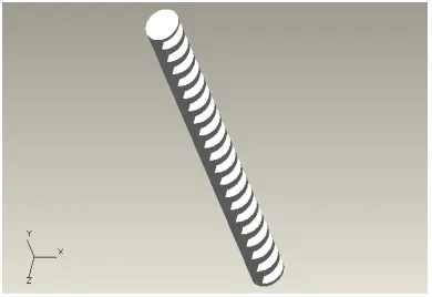
Figure 2. Rack of system
Figure 3. Pinion gear
III. WORKING
ISSN 2348 – 7968
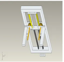
Figure 4. Showing the system arrangement
pinion connected to the runway to the open coil spring by the connecting plate.
The rack and pinion is connected to the connecting rod on either side to avoid collision with spring and rod and to provide maximum transmission of power to spur gear attached to it. The spur gear having 48 teeth is connected with the pinion having 24 teeth (2:1). The external spur gear is connected to the dynamo through which power is generated. Battery can be also used to store the electricity produced so, that it can be used later.
Rack and pinion is used to convert the reciprocating motion or the vertical motion of spring in to rotational motion. Due to this the spur gears connected to it starts to rotate transmitting the rotational motion into dynamo. For an average load of 50N is applied to the straphanger, 2V of power is produced from the dynamo.
IV. APPLICATIONS
Strap hanger finds application in buses and so this apparatus can be modified to be fitted in buses and trains.
The power generated from this apparatus can also be stored
In batteries for used later.
In one whole day, buses and trains at least run for 16 hours, also each compartment in trains have approximately 96 strap hangers.
If the entire strap hangers are connected to a common dynamo, the apparatus can be placed there to generate power.
The same concept can be utilized in the busses in cases of the seating arrangements were when the impact load is applied in the seats due the load applied the rack and pinion engages as a result the source of power is identified.
The same application can be utilized in the Jim working apparatus were the heavy weight lifting can attached with the rack and pinion arrangement were when the handle is pulled for one time source of power can be generated.
V. RESULTS AND DISCUSSION
Hence now different ways of results are obtained and these results when worked through various methodologies we obtain certain curves and pie charts. Obtain which designates the progress to a great extent.
Also we get a voltage of about 1.05v per usage of grab handles .hence for a single rotation of dynamo we obtain 0.3v.
Hence for one dynamo = 0.3v.
ISSN 2348 – 7968 Totally we obtain about 3.5 revolution combined
together.
Hence range of volt may be = 3.5 * 0.3 = 1.05v.
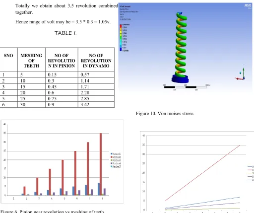
TABLE I.
Figure 6. Pinion gear revolution vs meshing of teeth
Figure 10. Von moises stress
Figure 7. Rack revolution vs Meshing of teeth
SNO MESHING OF TEETH
NO OF REVOLUTIO N IN PINION
NO OF REVOLUTION
IN DYNAMO
1 5 0.15 0.57
2 10 0.3 1.14
3 15 0.45 1.71
4 20 0.6 2.28
5 25 0.75 2.85
ISSN 2348 – 7968
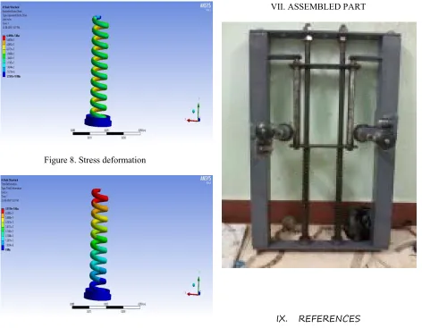
Figure 8. Stress deformation
Figure 9. Strain deformation
VI. CONCLUSION
It is found that power generation from straphanger is viable as we have designed and fabricated the working model. The things we learnt from this project are:
Also we get a voltage of about 1.05v per usage of grab handles .hence for a single rotation of dynamo we obtain 0.3v.
Hence for one dynamo = 0.3v.
Hence for two dynamo = 0.3*2 = 0.6v.
Totally we obtain about 3.5 revolution combined together.
Hence range of volt may be = 3.5 * 0.3 = 1.05v.
VII. ASSEMBLED PART
IX. REFERENCES
[1]. Abdulrazzak Pathan etl, Power Generation through Speed breaker, Department of industrial electronics shreeram polytechnic 2014.
[2]. Amanpreet Kaur, Shivansh Kumar Singh , Rajneesh , Parwez, Shashank , Power Generation Using Speed Breaker with Auto Street Light, International Journal of Engineering Science and Innovative Technology (IJESIT) Volume 2, Issue 2, March 2013.
[3]. P.M. Anderson and A.A. Fouad, „Power System Control and Stability‟, Galgotia Publications
[4]. S.S.Taliyan, B.B. Biswas, R.K. Patil and G. P. Srivastava, Electricity From Footsteps, ISSUE NO 313, BARC , (MAR. – APR) 2010 Pg no 47-50.