Implementing Labview Based Level
Controller
Prof. Prafulla Patil1
,
Nitesh Dongare2, Priyanka Bane
3, Amin Merchant
4, Ankit Pitla
5Assistant Professor, Dept. of Instrumentation Engineering, Vidyavardhini's College of Engg. and Tech., Vasai, India 1
UG Student, Dept. of Instrumentation Engineering, Vidyavardhini's College of Engg. and Tech., Vasai,
India
2,3,4,5ABSTRACT: The aim of our project is to design the PID controller using LabVIEW. The designing software use for
this purpose is LabVIEW developed by National Instruments. We also intend to use a DAQ card by ADAM model 4022T and also USB to RS485 converter UD2535-U of milestone for interfacing computer with the hardware. The hardware is a Multiloop Trainer Kit mounted with a tank whose level has to be controlled using a feedback control loop. The feedback control loop is form by a tank, level sensor, controller, I to P converter and control valve. The designed soft PID controller will replace the electronic PID on trainer loop kit.
KEYWORDS: DAQ card (Data Acquisition), LabVIEW (Laboratory Virtual Instrument Engineering workbench),
PID(Proportional Integral Derivative).
I .INTRODUCTION
In the present era of Industrial Automation, ease of work is one of the major concerns. This design enables the operator to operate the process sophisticatedly with an ease. Instead of giving manual inputs to the PID, the designed PID can adjust the input parameters just by mouse clicks. To obtain soft PID controller is possible by programming the PID algorithm using some high level language such as C, Fortran, Use of high level language allow us to use floating-point math. LabView is a very good high level language with an additional advantage of built in graphical user interface (GUI). It is quite user-friendly software and flexible to give better system performance. To provide improvements is an easy task in LabVIEW based soft PID. The system performance can be observed by the graphical representations of set point, process value, control signal, etc. The transient specifications such as overshoot, settling time, offset error, response time can be obtained from the graphs and PID algorithm can accordingly change the proportional gain, reset time and derivative time in order to get desired performance.
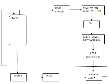
II. PROJECT FLOW
Fig. 1 shows the flow of project execution is: The designed PID will be generating the necessary controlling electronic signal. This signal will be acquired by DAQ card. The DAQ card transfers it to the I to P converter which will convert the electrical pulses 4-20mA into pneumatic signal 3-15psig to actuate the control valve. This conversion take place as the control valve acts on pneumatic signals only. The control valve controls the fluid flow to maintain the fluid level in tank. The tank is fitted with a capacitive level sensor and a transmitter. This assembly takes the level readings from tank and transmits it to the DAQ card. These values are called process values and are further processed into the designed PID. This way a closed loop system is formed.
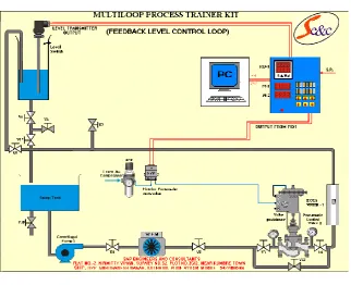
III. MULTI-LOOP TRAINER KIT (FLOW LOOP)
Fig. 2 Trainer Loop Kit
Fig.2 shows the major components of the control trainer kit forming feedback control level loop. The components are described as follows:
Supply tank: Supply tank is used for storage water. It is situated below the main setup assembly. The main setup
assembly covers the supply tank.
Level tank: Transparent level tank is supported on the support plate of the setup assembly. Graduated scale is provided
on the tank to indicate tank water level in %. The level tank has an outlet at bottom, which opens in to the supply tank. Outflow of the tank can be varied with the help of valve provided at the outlet.
Level sensor: Capacitance type level sensor transmitter is mounted on one of the level tanks. The level of water is
sensed and transmitted to interfacing unit for displaying the level and communicate to computer for control.
Control valve: A pneumatic control valve is supported on the support plate controls the flow of water to the level tank.
E/P Converter: The current to pressure converter (E/P converter) receives signal from computer through interfacing
unit. It converts supply pressure in to controlled output pressure in proportion to the signal received for pneumatic valve actuation.
Other units: Air regulator, pressure gauges, pump for water circulation, rotameter pneumatic piping and water piping
IV. DIFFERENT METHODS FOR HARDWARE INTEGRATION WITH LABVIEW
System integration is getting hardware and other data acquisition devices setup and configured such that you begin programming a system. It can be a major undertaking often taking more time than the programming, measurement or test you wish to perform. Integrating different hardware devices with traditional tools is littered with time wasting steps and possible incompatibilities, increasing risk. First you have to find the correct drivers for all of your hardware, and then you have to figure out how to install them and call them from software. Once your drivers are usable you need them to communicate with the hardware and learn the programming model that the driver designer decided was appropriate for that particular device. LabVIEW can help save you time and frustration by eliminating some of these steps and making others markedly easier. LabVIEW is one software tool that can span all of your hardware components. Drivers are readily available for common hardware devices. Each hardware driver shares a similar, familiar programming model, and examples of how to use the model install directly into LabVIEW. When configuring a test system, you often need to use many different types of instruments. These instruments can include GPIB or serial controlled instruments, modular instruments, image acquisition, motion control, USB, Ethernet, parallel port, and CAN. When using a PC to communicate with any type of instrument, you must be familiar with the properties of that instrument such as the communication protocol.
A. GPIB: GPIB or General Purpose Interface Bus is defined by ANSI/IEEE Standard 488.1-1987 and 488.2-1992 and
describes a standard interface for communication between instruments and controllers from various vendors. It is usually used in stand-alone bench top instruments to control measurements and communicate data. GPIB communication is conducted through a digital 8-bit parallel interface with three-wire handshaking and can achieve data transfer rates of 1 MB/s and higher.
B. SERIAL: Serial communication transmits data between a computer and a peripheral device. The serial
communication protocol uses a transmitter to send data one bit at a time over a single communication line to a receiver. This method works best when data transfer rates are low or when data must be transmitted over long distances. Most computers have at least one serial port, so additional hardware is not necessary. You should specify four parameters for serial communication: baud rate, data bits, parity bit, and stop bits. A character frame transmits each character as a start bit followed by the data bit. Several different standards exist for serial ports.
However these are the most common:
RS 232 (ANSI/EIA-232 Standard) (most popular) RS 422 (AIA RS-422A Standard)
RS 485 (EIA-485 Standard)
C. The Instrument I/O Assistant: The Instrument I/O Assistant is a LabVIEW Express VI that you can use to
communicate with message-based instruments and convert the response from raw data to an ASCII representation. When an instrument driver is not available, you can use the Instrument I/O to communicate with an instrument that uses a serial, Ethernet, or GPIB interface. The Instrument I/O Assistant organizes instrument communication into ordered steps. To use it, place your steps into a sequence. As you add steps to the sequence, they appear in the Step Sequence window. LabVIEW adds inputs and output terminals to the Instrument I/O Assistant Express VI on the block diagram that corresponds to the data you receive from the instrument.
D. Connect to Any Hardware: With LabVIEW, you can use all of your hardware with a single development
environment. Connectivity is made possible with driver software, which serves as the communication layer between LabVIEW and your hardware. LabVIEW driver software supplies seamless integration across multiple types of instruments, buses, sensors, data acquisition devices, boxed instruments, modular instruments, motion controllers and motor drives, machine vision and image processing hardware, wireless sensors and field programmable gate arrays (FPGAs). In the rare event that a LabVIEW driver doesn’t already exist, you also can import drivers from other programming languages or use low-level communication to implement your own driver.
E. NI Hardware: With more than 50 million I/O channels sold in the last 10 years, National Instruments is a global
than 200 data acquisition devices in LabVIEW on a variety of major buses and form factors, including USB, PCI, PCI Express, PXI, PXI Express, wireless, and Ethernet. In addition to data acquisition hardware NI also offers other specialty test, measurement, and control hardware. Modular instruments synchronize measurements, signal generation, radio frequency (RF), and switching components for automated test systems. NI programmable automation controllers combine the ruggedness of a PLC and the performance of a PC for industrial measurement and control applications. Vision devices also offer unique capabilities not found in many traditional sensors, such as verifying component positioning, counting physical elements, and reading bar codes. Each hardware type includes its own driver software for easy integration into LabVIEW. The drivers for all of these products were designed with LabVIEW in mind and feature convenient access to all of the available functionality of the hardware. The driver installs directly into LabVIEW and adds new functions to the Functions Palette so you waste no time locating and including support for your hardware. NI device drivers generally implement advanced features such as device name aliases and hardware simulation so you can develop software without tying yourself to a particular device. As long as your device supports The same functionality, the driver can adapt to the new device, even if the underlying technology changed dramatically, such as when moving from a PCI-based data acquisition device to a wireless device.
F. Instrument Driver Network for Adam 4022T: If 3rd party software wants to connect to ADAM series, It can be
communicated through OPC sever. For 4000,5000/485 it may apply OPC sever. For ADAM-5000/TCP, ADAM-6K series it may need Advantech Modbus TCP OPC sever. However this is not free software, customer needs to buy it. The ADAM OPC Servers support three communication protocol servers, including Advantech ASCII Command (AdamOPC),MODBUS/RTU(ModbusRTU),MODBUS/TCP (ModbusTCP) protocol. The servers provide the OPC interface for monitoring the ADAM 4000, ADAM 5000 and ADAM 6000 remote I/O series products. The Modbus TCP OPC Server is used for Ethernet communication and the others are for serial port communication. Therefore the Modbus RTU and Modbus TCPOPC servers could be used for other devices which are supported MODBUS/RTU and MODBUS/TCP protocol. The servers provide several fields for specifying the properties of devices, groups and tags. Those were implemented using advanced programming concepts of the most current version of the OPC specification for use in developing next generation industrial software applications.
G. Virtual Instrument Software Architecture (VISA): Virtual Instrument Software Architecture (VISA) is the basis
for the LabVIEW instrument driver. VISA does not directly provide instrumentation programming capability but serves as a high-level API that calls low-level drivers. VISA can control VXI, GPIB, serial, or other computer-based instruments and makes the correct driver calls depending on the type of instrument. In LabVIEW, VISA is a single library of functions that adapt to different instruments, so it is not necessary to use separate I/O palettes. The following terminology is used for VISA programming:
Resource: Any instrument in the system including serial and parallel ports
Session: Communications channel that is used by VISA to identify a specific reference to that instrument Instrument Descriptor: Exact name of the instrument
VISA is a high-level API used to communicate with instrumentation buses. It is platform independent, bus independent, and environment independent. In other words, the same API is used regardless of whether a program is created to communicate with a USB device with LabVIEW on a machine running Windows 7 or with a GPIB device with C on a machine running Mac OS X. USB is a message-based communication bus. This means a PC and a USB device communicate by sending commands and data over the bus as text or binary data. Each USB device has its own command set. You can use NI-VISA Read and Write functions to send these commands to an instrument and read the response from an instrument. Check with your instrument manufacturer for a list of valid commands for your instrument. Starting with version 3.0 NI-VISA supports USB communication.
V.SELECTION OF INTEGRATION METHOD FOR ADAM 4022T
(RS232, RS485, and RS422), USB, VXI, PXI, Ethernet, IEEE 1394, VISA, Modbus, and OPC Servers. The ADAM 4022T uses serial protocol RS 485 for data transmission. The data transmitted through and from ADAM 4022T card is converted to USB protocol which can be communicated by using NI VISA driver in LabVIEW.
VI.CONFIGURING NI-VISA TO CONTROL DEVICE
There are three steps to configure your USB device to use NI-VISA: 1. Create the INF file using the Driver Development Wizard. 2. Install the INF file and the USB device using the INF file. 3. Test the device with NI-VISA Interactive Control.
A. Create the INF File Using the Driver Development Wizard:
1. To open the NI-VISA Driver Wizard, select Start»All Programs»National Instruments»VISA»Driver Wizard. You can use this wizard to create an INF file for a PXI/PCI, or USB device. Because you are creating the driver for a USB device, click USB and Next.
2. For this step, you must know the USB vendor ID and product ID for your USB instrument. These numbers identify your USB device when you install it and address your device when you want to communicate with it.
3. Open the Device Manager from the Control Panel and find your device on the list, usually under "Other Devices." It may show a yellow exclamation mark indicating it is an unknown device. Double-click the device to open the properties. Select the Details tab and ensure that "Hardware Ids" shows in the attribute drop-down box. A string of characters will be displayed. The four characters to the right of "VID_" and "PID_" are your vendor ID and product ID, respectively. Write down the characters for your device, close the Device Manager, and unplug the device from the computer. If you do not see a match for your device under Device List, first try clicking Refresh.
4. In the NI-VISA Driver Wizard USB Device Selection window, choose other from the Device List. Click Next. Click
Yes. Enter the information you've collected about your device into the four fields click Next. The Output Files
Generation window is displayed. Enter a USB instrument prefix, select the desired directory in which to place these files, and click Next. The Installation Options window is displayed select the default selection is to install the generated files on your computer and is usually the best option. Once you select an option, click Finish to exit the wizard. The INF file is created in the directory you specified in the output file directory field in the previous window.
B. Install the INF files and the USB device: The installation of INF files is different for each version of Windows.
Because of the differences between Windows 2000/XP and Windows Vista/7 the NI-VISA Driver Wizard will create two an INF files, one for each OS group. Installation instructions are included in a header at the top of the INF file. Because INF files are ASCII text files, they can be read in any text editor such as Notepad. For detailed To install INF files on Windows 7 you will first need to be logged into an Administrator user account. You will need to unplug the USB device at this time so that the drivers will be properly associated with your device upon install. Copy the INF file to the INF folder. Right click on the INF file in C:\WINDOWS\INF and click Install. This process creates a PNF file for your device. You are now ready to install your USB device.
C. Test Communication with VISA Interactive Control:
1. Open Measurement & Automation Explorer (MAX). Select Tools»Refresh to refresh the view to ensure your device appears. Your USB device should be listed under Devices and Interfaces Your USB device is now installed and configured to use NI-VISA.
2 To test communication with this device, open MAX. Select Tools»NI-VISA»VISA Interactive Control.
VII. SOFT PID
The developed LabView Program accepts level reading and estimate PID controller output. Any LabView program is divided into two windows Front Panel and Block Diagram.
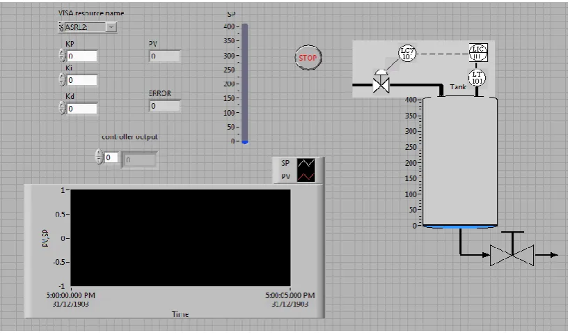
A. Front Panel
Fig. 3 Front Panel
Front Panel window is nothing but the GUI. Fig. 3 shows Font Panel developed for soft PID. The GUI has control buttons as Visa resource name, KP, Ki, Kd and SP. Visa resource name selects the hardware resource address to be communicated. Kp, Ki and Kd are PID gains which can be enter by operator after tuning of controller. Set point of level can be selected in between 0 to 400 mm by clicking on SP control button. Front Panel also has four indicators. PV shows process variable which is level of tank. Error shows value of difference between set point level value and current level of tank in mm. GUI also provides graph of set point and process variable with respect to time. Pictorial Tank indicator shows real time level of tank on Trainer Loop Kit. Stop icon is included to stop the program.
B. Block Diagram
The Block Diagram has five frames of flat sequence which will be executed in sequence. Fig. 4 shows Block Diagram. Frame 1: First frame has VISA Open function which opens a session to the device specified by VISA resource name and returns a session identifier that can be used to call any other operations of that device. Close the session with the VISA Close function. This frame also has VISA Configure Serial Port initializes the serial port specified by VISA resource name to the specified settings.
Frame 2: The second frame has VISA write function which writes the data from write buffer to the device or interface specified by VISA resource name. Whether the data is transferred synchronously or asynchronously is platform-dependent. Right-click the node and select Do I/O Synchronously from the shortcut menu to write data synchronously. The operation returns only when the transfer terminates. This function writes a command to read PV0 port of Adam 4022T.
Frame 3: Frame three has VISA read function which receives the response from ADAM 4022T which is nothing but level sensors reading. This Reading is then use to calculate PID controller output using various numeric functions. Frame 4: Frame four again include VISA write function which gives a command to send PID controller output calculated in frame 3 at output port AO0.
Frame 5: Fame 5 has VISA close Function which closes a device session or event object specified by VISA resource name. For each VISA session that you open, you should close the session when you are finished with it. This function accepts all available classes. Flat sequence is included in a while loop foe continuous execution of reading tank level and sending controller output.
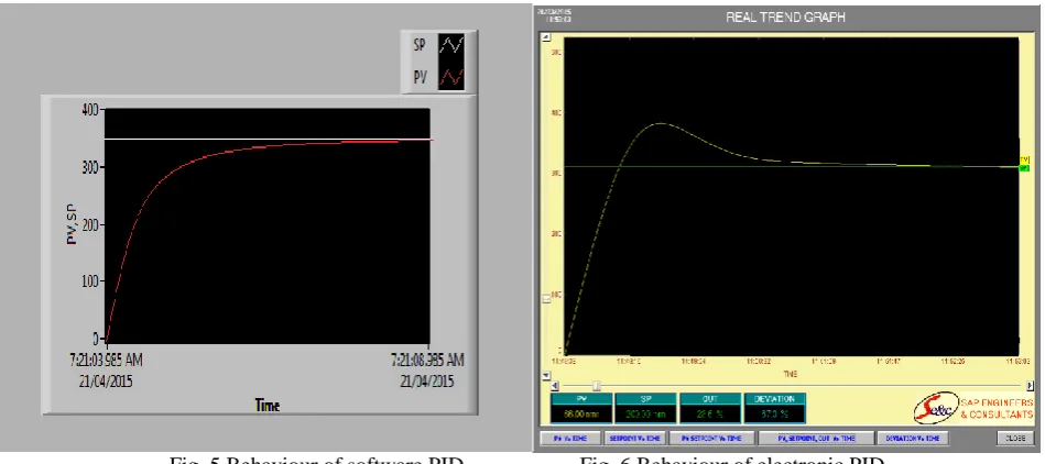
VIII. RESULT AND CONCLUSION
The developed soft PID is implemented on Trainer Loop Kit for efficient level control for a feedback level control loop. This implemented software PID replaces electronic PID.
Fig. 5 Behaviour of software PID Fig. 6 Behaviour of electronic PID
REFERENCES
[1] J. M. Jacob, “LabVIEW graphical programming for instrumentation,” Industrial Control Electronics. Prentice-Hall International, Inc., New Jersey,U.S.A, 1989.
[2] “LabView basics introduction,” National Instruments, Course Manual, U.S.A, 2002.
[3] Paper Entitled “An Automated Feedback System for Computer Organization Project” By Peter M. Chen, IEEE transactions on education, VOL. 47, NO. 2, MAY 2004
[4] Paper Entitled “A Systematic Method for Gain Selection of Robust PID Control for Nonlinear Plants of Second-Order Controller Canonical
Form” By, Pyung Hun Chang, IEEE TRANSACTIONS ON CONTROL SYSTEMS TECHNOLOGY, VOL. 17, NO. 2, MARCH 2009
[5] Ian Fair-weather, “A Developer's Guide to Real World Integration”, Chapman and Hall/CRC; Her/Cdr edition (19 January 2012)
[6] Mohammad A. K. Alia, Tariq M. Younes, Shebel A. Alsabbah, A Design of a PID Self-Tuning Controller Using Lab VIEW Journal of Software Engineering and Applications, 2011, 4, 161-171.
[7] K. V. L. P srinivas1, P Durga Prasada Rao2, “Modelling and simulation of complex, Control systems using labvVIEW,” International Journal of Control Theory and Computer Modelling, IJCTCM, VR Siddhartha Engineering College, Vijayawada, India.
[8] J. M. Jacob, “LabVIEW graphical programming for instrumentation,” Industrial Control Electronics. Prentice-Hall International, Inc., New Jersey ,U.S.A, 1989.
[9] B. E. Paton, “LabVIEW graphical programming for instrumentation,” Programming for Instrumentation. Prentice Hall PTP, New Jersey , U.S.A, 1999.
[ 10] P. P. P. Harsh Kaji, Shruti Annigeri, “Designing PID controller using LabVIEW for controlling fluid level of vessel,” International Journal of Engineering Research and Applications (IJERA), vol. 3, pp. 1329–1333, March -April 2013.trol Electronics.
[11] R. A. . S. Mohan, “Complete industrial solution for automation in temperature and humidity monitoring using Lab VIEW,” VIT University, Vellore, India, p. 5.
[12] M. K. A. Z. MOHAMMAD A.K. ALIA, “A closed-loop temperature control system by utilizing a LabVIEW custome-design PID controller,” Al-Balqa Applied University Amman, Jordon, p. 4.
[13] James R. Matey, “General Principles for Applications of Computers in Experimental Physics,” Computers in Experimental Physics, Vol. 7, No. 1, pp. 12-17, Jan/Feb 1993.
[14] Robert Hennessey, “Lab VIEW-Based Automatic Control Systems Laboratory Using Local and Remote Experimentation Approaches”, Electrical and Computer Engineering Department, University of Texas at El Paso