1470 |
P a g e
VOLTAGE DISTRIBUTION ACROSS STRING
INSULATORS BY SPHERE GAP METHOD
Prof. Ch.Kavitha Chenna Reddy
1, Dr.S.Sujitha
2Assistant professor, EEE Department,New Horizon College of Engineering
ABSTRACT
Insulators for overhead lines are considered to be of basic importance to the transmission system, through their ability to insulate the power lines as well as their function in carrying the weight of the line conductor. For higher voltages, a string of suspension insulators is used where the number of insulator units used depends on the voltages of the lines. The voltage is not equally shared between the units in a suspension insulator string. The unequal distribution of the voltage is due to the presence of stray capacitance of the hardware to earth and to line. Hence in this paper we are calculating the voltage distribution by sphere gap methods and comparing the results and we are also trying to make the voltage distribution across the insulators as uniform as possible by Guard rings. In this paper, we are also calculating the voltage distribution across the string insulators theoretically and comparing the results with practical values.
I. INTRODUCTION
1471 |
P a g e
II. CONVENTIONAL METHODS
Methods of Measurement of Voltage Distribution:
The methods used for measurement of voltage distribution across the string insulator under
AC voltages in dry conditions, are discussed in the following sections.
Sphere Gap Method:
This method consists of installing a sphere-sphere gap across the desired insulator, and then
increasing the applied voltage to the string until the gap sparks over, thus determining the
relative value of the voltage across the insulator.
Experimental Setup for Measurement of AC Voltage Distribution along String
Insulators
The experiment setup used for the voltage distribution by sphere-gap method under AC
voltage is shown in the below figure Theexperimental setup consisted of 4 and 6 strings of
porcelain and glass disc insulators, (AC voltage) suspended vertically by means of a rope.
The high voltage is applied to the pin of lowest insulator of the string. The porcelain
insulators used were new, clean and dry. A power frequency test transformer of 50kV, 5KVA
was used as the voltage source for the study of AC voltage distribution for 4 and 6 insulators
string.
Experimental Procedure for Measurement of Voltage Distribution under AC Voltages
By Sphere Gap Method
The experimental setup used for the study of AC voltage distribution is shown in the fig.1
where 2.0cm diameter sphere-gap is used for measurement of voltage distribution.
1472 |
P a g e
In this method of measurement, the spacing of the sphere-sphere gap was pre-set at a
particular value. The electrode system was then connected across the insulator and the
voltage applied to the string was raised till the spark over of the sphere-gap occurred. The
above procedure was repeated for three or four times, and the average of these values was
considered for the evaluation of the percentage voltage shared by the given insulator, which
is expressed as,
%V=Spark over voltage of the sphere-sphere
Voltage applied to the string to cause the
sphere gap breakdown
The procedure is repeated on every insulator of 4 and 6 disc insulator strings. The percentage
voltage shared by all the insulators was calculated after applying correction for the
corresponding measured values to the string
Calibration of Sphere Gap
The voltage distribution of string of insulators is determined by sphere-gap method.
Therefore break down of sphere-gap and its characteristics are very much important for
accurate values of voltage across the insulators therefore the calibration of sphere-gap was
carried out.
The procedure adopted is as follows:
The gap-spacing of the sphere-gap was kept at a particular value and the voltage was
increased till spark over display. Average of 3 spark over values were considered for
evaluation. The gap-spacing was increased by 1 mm or 2 mm and the procedure is repeated.
The entire break down values was corrected to the standard atmospheric condition. The graph
of break down voltage V/s gap-space was drawn for the corresponding sphere which was
1473 |
P a g e
Calibration of spheres
III. SPHERE GAP METHOD USED FOR MEASUREMENT OF VOLTAGE WITH
AND WITHOUT GUARD RING
The experiment setup used for the voltage distribution by sphere-gap method with and
without guard ringsThe above figure shows the arrangement of voltage distribution without
guard rings
1474 |
P a g e
Fig.3 Sphere gap arrangement with the appearance of spark between the spheres without guard ring
Fig.4The arrangementof voltage distribution with guard rings and the theoretical values is
calculated as below
Voltage Distribution Across 4 Disc Insulators Under AC Voltage Without Guard Ring
1475 |
P a g e
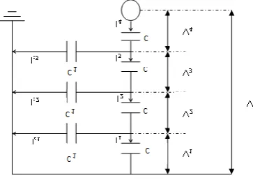
Fig 5 V across String Insulators
Let,
k = Capacitance per ground = C1
Capacitance per insulator C
Let V be the operating voltage (line to ground) V=V1+V2+V3+V4
I2 =I1+IC1
2πfCV2 = 2πfC1V1+2πfCV1
On simplifying we get
V2 = V1 (1+k), where k = C1/C
I3 = I2+Ic2
2πfCV3 = 2πfC1 (V1+V2) +2πfCV2
V3= (k2+3k+1) V1 I4 = I3+Ic3
2πfCV4 = 2πfC1 (V1+V2+V3) +2πfCV3
V4= (k 3
+5k2+6k+1) V1
V=V1+V2+V3+V4 Normally V1<V2<V3<V4
Thus the lowermost unit is full stressed or utilized. As k value decreases the division of voltage becomes more equalized. “String Efficiency” is a measure of utilization of material in the string and is defined as
String Efficiency = Voltage across the string n*voltage across unit
adjacent to line
Where, n is the number of insulators. For 4 discs
1476 |
P a g e
4*V4Calculation for 4 Disc Insulators
k = C1= 3pF = 0.1
C 30pF
V2 = V1 (1 + k) = V1 (1 +0.1)
V2= 1.1 V1
V3 = V1 (1 + 3k + k 2
) =V1 (1 +3* 0.1+ 0.1 2
) V3 = 1.31 V1
V4 = V1 (1 + 6k + 5k2 + k3) = V1 (1 + 6*0.1 + 5*0.12 + 0.13)
V4 = 1.65 V1
V= V1 + V2 + V3 + V4
38.10 = V1 + 1.1 V1 + 1.31 V1+ 1.65 V1
5.06 V1 = 38.10
(V1+V2+V3+V4) = 72.06%
Theoretical String Efficiency = (V1+V2+V3+V4)
4V4
Theoretical String Efficiency=76.67%
Practical String Efficiency = (V1+V2+V3+V4)
4V4
Practical String Efficiency = 72.06%
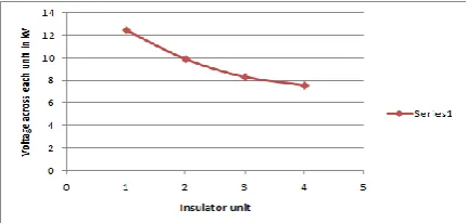
Theoretical Calculation without guard ring :
Insulator Number
%age of Voltage Shared
Voltage in kv
1(Line End)
32.6
12.42
2
25.88
9.86
3
21.73
8.28
1477 |
P a g e
Thus the String efficiency and total percentage voltage shared by each insulator without
guard ring practically is taken below and the graph is plotted with voltage across each unit
and values are given
Fig. 6: Graph between voltage across each unit and given insulator value
Fig. 7: Graph between percentage voltage shared by each unit and given insulator value
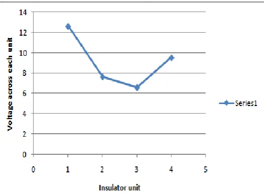
Standard Method by sphere gap without Using Guard Ring For 2mm Gap Spacing
Insulator Number
Breakdown Voltage in
kV
%age of Voltage
Shared
Voltage in kv
1(Line End)
15
33.33
12.6
2
25
20
7.62
3
29
17.64
6.56
4(Ground End)
20
25
9.52
Voltage distribution across a string of 4 disc insulators calculated practically for 2mm gap spacing
without guard ring
Standard BDV for 2mm spacing is 5kV(Corrected)
String Efficiency (%)
Total %age of Voltage Shared
1478 |
P a g e
String efficiency and total percentage voltage shared by each insulator
Fig. 8: Graph between voltage across each unit and given insulator value
Fig. 9: Graph between percentage voltage shared by each unit and given insulator value
Standard Method by Using Guard Ring for 2mm Gap Spacing
Insulator Number
Breakdown Voltage in
kV
%age of Voltage
Shared
Voltage in kv
1(Line End)
15
25.12
13.049
2
16
24.13
13.049
3
15
25.13
13.057
1479 |
P a g e
Voltage distribution across a string of 4 disc insulators calculated practically for 2mm
gspacingusingguard rings
Thus the voltage is distributed equally by means of guard ring and the different comparison
of string efficiency and total percentage of voltage shared for a string of 4 disc insulators is
shown below
Comparison of String Efficiencyfor a String of 4 disc Insulators
Theoretical
Standard method
without guard ring
76.6
72.6
Comparison of Total Percentage of Voltage Shared For a String of 4 disc Insulators
Theoretical
Standard method without
guard ring
99.8
95.6
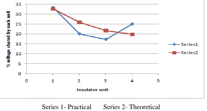
The belowgraph shows the comparison of voltage distribution with theoretical and practical
method which is sphere gap method.
Series 1- Practical
Series 2- Theoretical
Fig. 10: Graph showing comparison of voltage distributionboth theoretically and practically.
String Efficiency (%)
Total %age of Voltage Shared
1480 |
P a g e
IV. CONCLUSION
The conclusions that can be drawn from the tests, which have been carried out to determine the voltage distribution for string of 4 disc insulators subjected to AC voltage using sphere-gap method with and without Guard ring are given below.Here the voltage distribution along 4 disc insulators is obtainedtheoretically and practically.The voltage distribution along 4 disc insulators calculated theoretically shows that the distribution is linear and the voltage goes on decreasing as we move from the line end to ground end but, the voltage distribution along 4 disc insulators calculated practically shows that the distribution is nonlinear and the voltage goes on decreasing as we move from the line end and slightly rises at the ground thus we can conclude that sphere gap method is efficient method.The voltage distribution for 4 disc insulators is approximately made uniform by connecting guard ring at the line end. This test shows that the line end insulator shares a higher percentage voltage which leads to Radio Interference Voltage.
REFERENCES
1. “EHV Transmission Line Reference Book”, Edition Electric Institute, New York, USA, 1968.
2. N. PATTANADECH, P. YUTTHAGOWIT, had determined Problems, Investigation Methods, andSolution of Using String Suspension Insulators.
3. Mikio Kawai, “Reference at project UHV on the performance of Contaminated insulator”, IEEE Trans.PAS, 92, pp.1102-1110, 1973.
4. Hiroshi Fukui, Katsuhio Naito, Takashi Irie and IwaoKumoyo, “A practical study on Application of semiconducting Glaze Insulator to Transmission Lines”, IEEE, Trans.PAS, vol.PAS, 93, pp.1430-1443, 1974.
5. C.T.Wu,T.C.Cheng, and A. Rodriguez-pene, “A study on the use of internal Grading to improve the performance on Insulators”, IEEE, TransEI-16,No.3,pp.250-257,1981.
6. Vassiliki T. Kontargyri, Ioannis F. Gonos, Member, IEEE, Ioannis A. Stathopulos, and Alex M.Michaelides