1193 | P a g e
Improved Performance of Load Sharing and Voltage
Regulation in Paralleled DC-DC Converters using
Modified Droop Control Scheme
Amrita Jain
1, Shobhit Jain
2, D.K.Palwalia
31,2,3
(Department of Electrical Engineering, Rajasthan Technical University, India)
ABSTRACT
This paper introduces modified droop control scheme for considerable improving the load sharing and voltage
regulation performance in parallel DC-DC converters in DC microgrid. The control design overcomes
problems such as unequal current distribution and voltage drop. This method reduces the circulating current
and provides improved current sharing among parallel converters. The proposed analysis and control scheme is
introduced for two DC-DC boost converters. Simulation studies verify the proposed approach.
Key Terms-
Current sharing, droop control method, DC microgrid, parallel DC-DC converters.
voltage regulation.
I.INTRODUCTION
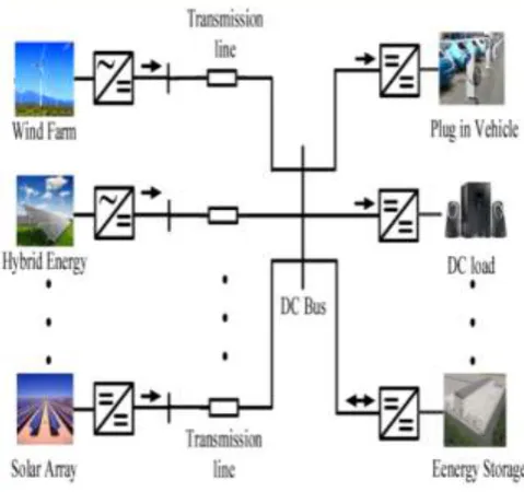
The concept of low voltage DC microgrid is shown in fig. 1. There are lot of issues associated with a low
voltage DC microgrid but this work mainly shows the voltage deviation control and load sharing issues between
various DERs linked with DC-DC converters to a dc microgrid [1]-[3].
Paralleling of DC-DC converters is a key technology for a distributed power supply system in DC microgrid. It
provides proper control and synchronization among power supply modules to sustain power balance between
source and loads [4].
Without current sharing control scheme, even small disturbances in modules, output voltages can cause the
output currents to be considerably different [5]-[6]. Distributed power converters include several advantages like
(i) high reliability (ii) easy scalability (iii) design standardization (iv) effectiveness (v) improved power quality
(vi) improvement in system performance etc [7].
Various current control schemes have been proposed to control the current imbalance [8],[9]. Among all, droop
current control is mainly used because it provides a redundant configuration for a high reliability power system
[10]. Existing droop control scheme causes poor voltage regulation. To address this limitation modified droop
1194 | P a g e
Fig. 1. Structural diagram of low-voltage dc microgrid.II.CONTROL
STRATEGY
FOR
LOAD
SHARING
ISSUES
This section presents load sharing imbalance for parallel DC-DC converters connected to a low voltage
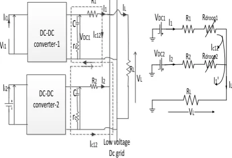
microgrid. Fig 2(a) shows the converter configuration of two parallel DC-DC boost converters interfaced with
PV array. The fig is characterized by their output voltages, output current and cable resistances as VDC1 ,VDC , I1,
I2 and R1, R2 respectively. Case studies for current division, circulating current and cable resistances are
mentioned in table –I. Fig. 2 (b) shows the equivalent circuit of output side of parallel converters.
Case studies for current distribution and load sharing are presented in table-I.
TABLE –I
Case Studies for Load Sharing and Current Division
Case VDC1,VDC2 R1, R2 I1, I2 I C12/IC21
1 equal Equal equal zero
2 equal Different different zero
3 equal Equal different non zero
1195 | P a g e
Rdroop1
R1
I
1V
DC1V
LV
DC2I
2 R2 Rdroop2
I
c12I
1'
RL
I
LDC-DC converter-2
Low voltage Dc grid DC-DC
converter-1
V
i1C
I
i1I
i2r
cR2
r
cC
V
DC1R1
I
2I
1I
c12I
c12I
LRL
V
LFig.2.(a) Parallel dc–dc converters with different output voltages. (b) Steady state equivalent circuit for
the dc output side.
A. Mathematical estimation of currents sharing in two parallel boost converter:
By using application of Kirchhoff’s Voltage Law (KVL) in fig.(2)
(2)
The output currents in converters are expressed by following equations:
(3)
(4)
The circulating current can be expressed as:
(
If R1=R2)
(
If R1≠R2)
(5)Now RL>>R1and R2 so the product R1.R2 can be ignored. By substituting (5) in (3) and (4) we get
1196 | P a g e
Load Current (I1’) Circulating Current (IC12)
(7) Load Current (I2’)
Circulating Current (IC21)
III. VOLTAGE DEVIATION CONTROL BY INSERTING R
DROOPThis part of paper gives an overview about the method which allows the distribution of converter currents by
connecting a series resistance Rdroop to each converter as shown in fig 3(a). The equivalent circuit is shown in
fig. 3(b).
Rdroop1
R1
I1
VDC1
VL
VDC2 I
2 R2 Rdroop2
Ic12
I1'
RL IL
DC-DC converter-2
Low voltage Dc grid DC-DC
converter-1
Vi1
C
Ii1
Ii2
rc
R2
rc
C
VDC1
R1
I2
I1
Ic12
Ic12
IL
RL
VL
Fig.3. (a) Two parallel boost converter in series
with Rdroop (b) study state equivalent circuit of dc output side.
IV.
PROPOSED
CIRCULATING
CURRENT
CONTROL
METHOD
The major purpose of this segment is to manage load sharing and to diminish circulating current from the
converters by using proposed control method.
A. Droop Index Scheme (DI)
In parallel DC-DC converters there is uniform current distribution in case of proper current sharing hence no
circulating current occurs in the parallel system. At the same time realisation of a voltage drop in converter
output voltage due to inclusion of series resistance. Hence, DI is expressed as a function of power output loss
and current sharing difference
.
(8)
Where the Ploss belonging to fig. 3 (b) can be written as
1197 | P a g e
In above equation (8), “Ni” represents normalization of variation in current contribution based on the rated load
current and “Np” indicates normalization of power output loss. Additionally, the normalized power loss
eventually indicates the reference voltage drop.
The calculation of Minimum droop index can be considered by varying Rdroop and its highest value will depend
on the voltage control i.e. the product of Rdroop and output current have to be smaller amount than the maximum
deflection in dc voltage. The calculation of current sharing variation for two boost converters depended on Fig.3
(b) by suggesting variables x, y, and m given as
, , (10)
The converter output currents I1 and I2 can be given as
(11)
(12)
Where
+ (
From eq.(10) the current sharing difference |I1-I2| is calculated as
(13)
Correspondingly, the output power loss can be expressed as
(14)
Where
By changing the value of Rdroop2 from zero to its maximum value the minimum value of DI can be carried out.
V.
SIMULATION
RESULTS
To illustrate the above mentioned scheme and to validate the minimization of circulating current, experimental
and comparative set up is carried out for both cases using modified droop index method. The simulation
1198 | P a g e
Rdroop1
Rdroop2
Discrete, Ts = 5e-05 s.
powergui
Vout
v +
-V2 V1
Subtract
+
+
+
+
+
+
+
+
+
Vout Pulse
PWM2 Vout Pulse
PWM
Ic12
i +
-i +
-Gate Pulse
V2+ RL
V2-RL1 Converter2
PWM V1+
RL
V1-RL1
Converter 1
Fig.4. Simulation model of two parallel boost converters
TABLE- II
Parameters of Boost Converters
Parameters Symbol Value
Input voltage Vin 24V
Output voltage Vout 48V
Filter inductor L 710µH
Filter capacitor C 220µF
Nominal switching frequency fSW 10kHz
ESR of filter inductor rL 0.03Ω
1199 | P a g e
B. Paralleling of two boost converters without adding any droop control method.TABLE-III
Simulation Results without Droop Control
Time(s) VDC1,VDC2,VL IL(I1,I2) ∆Ierr (%) Ic
0-0.1s 48,48, 47.74 5(2.5,2.5) 0 0
0.1-0.3s 48,48.45,47.98 5(0.2,4.8) (4.6)
92%
2.3
0.3-0.5s 48,48,47.74 5(2.5,2.5) 0 0
0.5-0.7s 48,47.52,47.5 5(4.8,0.2) (4.6)
92%
2.3
The above table shows the % current error without any droop method. When converter output voltages VDC1 and
VDC2 are different then the % current error was found to be 92% which is not proper. The simulation results
without droop control method are shown in fig. (5), (6) and (7).
C. Paralleling of two boost converters with Proposed droop index calculation
TABLE-IV
Simulation Results with Rdroop Using DI Calculation
Time(s) VDC1,VDC2,VL IL(I1,I2) ∆Ierr
(%)
Ic
0-0.1s 48,48, 47.15 5(2.5,2.5) 0 0
0.1-0.3s 47.99,48.46,47.3
6
5(1.9,3.1) 24% 0.12A
0.3-0.5s 48,48,47.15 5(2.46, 2.54) 1.6% 0.04A
0.5-0.7s 47.92,47.52,46.9
9
5(3.2,1.8) 28% 0.14A
The simulation results by calculating the value of Rdroop using DI method is shown in above table. The output
cable resistance for each converter is taken 100mΩ. The table clearly shows the % current sharing error for the
different possibilities. The simulation results using modified droop index method are obtained in fig (8),(9) and
(10). It is observed that the % current sharing error is limited by 24% which is less as compared with previous
1200 | P a g e
0 2 4 6 (b) C ur re nt ( A )0 500 1000 1500 2000 2500 3000 3500 4000 4500 5000
-5 0 5 time(s) C ur re nt ( A ) I1 I2 47 47.5 48 48.5 V ol ta ge (V ) (a) Vdc1 Vdc2 VL
Fig.5 Simulation results without Rdroop calculation upto 0.3s (a) converter output voltages, load voltage.
(b) Output currents (c) circulating current.
47.5 48 48.5 V o lt a g e (V ) 0 2 4 6 C u rr e n t( A )
0.2 0.25 0.3 0.35 0.4
-6 -4 -2 0 Time(s) C ir c u la ti n g c u rr e n t (I c 1 2 ) Vdc1 Vdc2 VL I1 I2
Fig.6. Simulation results without Rdroop calculation during 0.3s-0.5s (a) converter output voltages, load
1201 | P a g e
47 47.5 48 V o lt a g e (V ) 0 2 4 6 c u rr e n t( A )0.2 0.25 0.3 0.35 0.4
0 2 4 6 Time(s) c ic u la ti n g c u rr e n t( Ic 1 2 ) data1 Vdc1 Vdc2 VL I1 I2
Fig7.Simulation results without Rdroop calculation up to 0.5-0.7s (a) converter output voltages, load
voltage. (b) Output currents (c) circulating current
46 47 48 49 (a) V ol ta ge ( V ) 1.5 2 2.5 3 (b) C ur r e nt ( A )
0.05 0.1 0.15 0.2 0.25 0.3
-2 -1 0 1 Time(s) (c) I c 12( A ) VL VDC1 VDC2 I1 I2
Fig.8 Simulation results using modified Rdroop calculation upto 0.3s (a) converter output voltages, load
voltage. (b) Output currents (c) circulating current.
1 2 3 4 (b) C u r r e n t( A )
0.2 0.25 0.3 0.35 0.4
-2 -1 0 1 Time(s) (c) I c 1 2 ( A ) 47 47.5 48 48.5 (a) V o lt a g e ( V ) I1 I2 VL VDC1 VDC2
Fig.9. Simulation results using modified Rdroop calculation during 0.3s-0.5s (a) converter output voltages,
1202 | P a g e
46
48
50
(a)
V
o
l
t
a
g
e
(
V
)
0 2 4
(b)
C
u
r
r
e
n
t
(
A
)
0.2 0.25 0.3 0.35 0.4
-2 0 2
Time(s)
(c)
I
c
1
2
(
A
)
I1 I2
VL
VDC1
VDC2
Fig10.Simulation results using modified Rdroop calculation up to 0.5-0.7s (a) converter output voltages,
load voltage. (b) Output currents (c) circulating current
VI. CONCLUSION
In this paper, the modified droop index method for load sharing and voltage regulation for parallel DC-DC
converters for low voltage dc micro-grid is developed. It allows better current sharing between dc-dc converters.
This proposed scheme provides improved load current contribution by eliminating circulating current between
the converters and boost up the stability of micro-grid. The performance of different techniques using parallel
converters has been implemented through experimental and simulation studies in MATLAB.
REFERENCES
[1] S. Bull, “Renewable energy today and tomorrow,” Proc. IEEE, vol. 89, no. 8, pp. 1216–1226, Aug. 2001. [2] N. Tummuru, M. K. Mishra, and S. Srinivas, “Multifunctional VSC controlled microgrid using instantaneous
symmetrical components theory,” IEEE Trans. Sustain. Energy, vol. 5, no. 1, pp. 313–322, Jan. 2014.
[3] A. Bonfiglio et al., “The smart poly generation microgrid test-bed facility of Genoa University,” in Proc.
IEEE UPEC Conf., Sep. 2012, pp. 1–6.
[4] P. Basak, S. Chowdhury, S. H. nee Dey, and S. Chowdhury, “A literature review on integration of
distributed energy resources in the perspective of control, protection and stability of microgrid,” Renew.
Sustain. Energy Rev., vol. 16, pp. 5545–5556, Oct. 2012.
[5] D. Salomonsson, L. Soder, and A. Sannino, “An adaptive control system for a dc microgrid for data centers,”
IEEE Trans. Ind Appl., vol. 44, no. 6, pp. 1910–1917, Nov. 2008.
[6] T. Vandoorn, B. Meersman, L. Degroote, B. Renders, and L. Vandevelde, “A control strategy for islanded
1203 | P a g e
[7] S. Augustine, M. K. Mishra and N. Lakshminarasamma, “Circulating current minimization and current
sharing control of parallel boost converters based on droop index,” in Proc. IEEE SDEMPED Conf., Aug.
2013, pp. 454–460.
[8] J. Rajagopalan, K. Xing, Y. Guo, F. Lee, and B. Manners, “Modeling anddynamic analysis of paralleled
dc/dc converters with master-slave current sharing control,” in Proc. IEEE 11th Annu. APEC Conf., vol. 2,
Mar. 1996, pp. 678–684.
[9] I. Batarseh, K. Siri, and H. Lee, “Investigation of the output droop characteristics of parallel-connnected dc–
dc converters,” in Proc. IEEE 25th Annu. PESC Conf., Jun. 1994, vol. 2, pp. 1342–1351.
[10] S. Anand and B. Fernandes, “Modified droop controller for paralleling of dc–dc converters in standalone dc