PERFORMANCE ENHANCEMENT OF A ROTARY
FURNACE: A HARBINGER TO POLLUTION FREE
CASTINGS
Dilip Kumar
1, Ranjit Singh
2, Ashok Yadav
31,2,3
Department of Mechanical Engineering, Faculty of Engineering,
Dayalbagh Educational Institute, (India)
ABSTRACT
The Iron foundries have been playing a vital role in the industrial development of India. The major problems
being faced by iron foundries are restrictions on energy consumption by TERI and emission levels due to which
majority of coal fired ferrous foundries in Agra have been closed by an order of the Hon’ble Supreme court of
India. The present state of foundries in Agra reveals that extensive research is necessary to develop an
ecofriendly and energy efficient furnace for Ferrous Foundries. Therefore, A 200 Kg capacity Rotary Furnace,
have been designed and developed in DEI and studied for its technical feasibility, economic efficiency, energy
consumption and emission levels.
Experiments conducted with heat exchanger and different fuels and their combination improved the energy
consumption and pollutants but still not within the limits of TERI and CPCB. So, a modified heat exchanger has
been designed. Experiments are conducted with the changed nozzles, modified heat exchanger and using
jatropha and LDO mixed fuel. The furnace parameters are optimized experimentally and found that using Reillo
burners, modified heat exchanger, new refractory lining of the furnace rotating at 1RPM using 10% excess air
and 410 degrees air preheat, CPCB limits and TERI limits are fully satisfied. Also Quality of the casting is
found excellent. Hence, Rotary Furnace with the above modifications will be a boon for the foundry industry of
Agra and India at large.
Keywords—Bio fuel; Heat losses; Iron foundries; Rotary furnace
I.
INTRODUCTION
desired level and recommended urgent anti-pollution measures in Cupolas. He suggested that a suitable scrubber, cyclone or bag filter may be put along with a dry/wet arrester to reduce the particulate emission level.
Bandopadhya[2] also emphasized the problems and strategies of environmental pollution in CI foundries.Bandopadhya et al.[3] emphasized energy, environment and resource management in Indian mineral industries.Banerjee[4] emphasized that besides gasses and fumes, noise also poses serious problems.Datta et al.[5] advocated the installation of medium frequency coreless induction melting furnace.Landge[6] recommended the use of high energy venturi scrabbling system.
Maiti[7] suggested deletion and monitoring techniques on the basis of fundamental principles involved, mode of operation, accuracy of measurement etc. for environmental pollution from foundries.
Mohammad et. al.[8] emphasized the installation of Induction furnace for melting as they have lower emission values.
Panigrahi[9] suggested the use of dry spark arrester, wet spark arrester, cyclones, bag filter, tower wet dust catcher with venture pipe and waste water treatment.
Parthasarathy et al. [10] recommended the use of ESP (Electro-static Precipitators), bag filters, wet collectors and cyclones for the control of air pollution in the foundries.Raizada[11] suggested a water cooling system for induction furnace.Selby [12] discussed the advantages of rotary furnace.Tiwari[13] stressed the need to install electric furnace to get rid of cupola emission.
PurshottamKumar[14]emphasized on using a Rotary furnace to avoid the additional cost of pollution control equipment for producing castings in pollution free environment using different fuels and combustion equipment. The results indicated that present combustion equipment used gives improvement in pollution contents almost to the level of CPCB norms but energy requirements are still high as per the TERI norms.
The literature surveyed and present state of foundries in India reveals that extensive research work is necessary to develop an ecofriendly and energy efficient furnace for Ferrous Foundries.A 200 kg rotary furnace with a heat exchanger was designed, fabricated and used for investigations by the Faculty of Engineering, DEI, Dayalbagh. Rotary furnace made of 7 mm thick MS plates lined with mortar and refractory bricks have been used to study the emission level and energy consumption.
II.DEVELOPMENTS
IN
DESIGN
OF
COMPACT
HEAT
EXCHANGER
It was observed during experimental investigations that reducing (excess air) i.e.combustion volume and supplying oxygen additionally the specific fuel consumption is reduced.In view of this development, design of compact cross flow heat exchanger is carried out . The following datas are considered
Approximate volume of air =450.0m3,approximate time of one heat =40.0 minutes, oxygen consumption inone heat =38.5 m3, Atmospheric air temperature at inlet of exchanger =27.00C, Air temperature at exit from exchanger=500.00C,
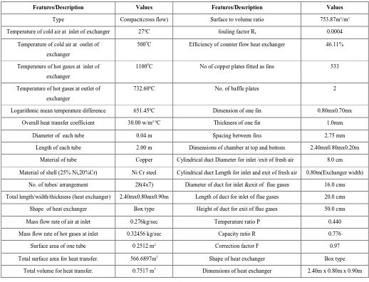
TABLE I. THE DESIGN DATA OF COMPACT CROSS FLOW HEAT EXCHANGER FOR IMPROVED
PERFORMANCE FOR THE DESIGNED FURNACE
Features/Description Values Features/Description Values
Type Compact(cross flow) Surface to volume ratio 753.87m2/m3
Temperature of cold air at inlet of exchanger 270C fouling factor R
f 0.0004
Temperature of cold air at outlet of
exchanger
5000C Efficiency of counter flow heat exchanger 46.11%
Temperature of hot gases at inlet of
exchanger
11000C No of copper plates fitted as fins 533
Temperature of hot gases at outlet of
exchanger
732.600C No. of baffle plates 2
Logarithmic mean temperature difference 651.450C Dimension of one fin 0.80mx0.70mx
Overall heat transfer coefficient 30.00 w/m2 0C Thickness of one fin 1.0mm
Diameter of each tube 0.04 m Spacing between fins 2.75 mm
Length of each tube 2.00 m Dimensions of chamber at top and bottom 2.40mx0.80mx0.20m
Material of tube Copper Cylindrical duct Diameter for inlet /exit of fresh air 8.0 cm
Material of shell (25% Ni,20%Cr) Ni Cr steel Cylindrical duct Length for inlet and exit of fresh air 0.80m(Exchanger width)
No. of tubes/ arrangement 28(4x7) Diameter of duct for inlet &exit of flue gases 16.0 cms
Total length/width/thickness (heat exchanger) 2.40mx0.80mx0.90m Length of duct for inlet of flue gases 20.0 cms
Shape of heat exchanger Box type Height of duct for exit of flue gases 50.0 cms
Mass flow rate of air at inlet 0.276kg/sec Temperature ratio P 0.440
Mass flow rate of hot gases at inlet 0.32456 kg/sec Capacity ratio R 0.776
Surface area of one tube 0 2512 m2 Correction factor F 0.97
Total surface area for heat transfer. 566.6897m2 Shape of heat exchanger Box type
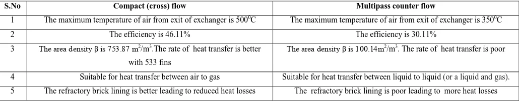
TABLE II. COMPARISION OF COMPACT (CROSS FLOW) AND MULTIPASS (COUNTER FLOW) HEAT
EXCHANGER
By modifying the heat exchanger the area density is increased to a very high value and efficiency is also increased from 45.36% to 46.11% and number of fins is increased from 500 to 533.45.36% was the efficiency and 500 fins were used in the heat exchanger used by PurshottamKumar.
III.EXPERIMENTAL
EVALUATIONS
TheExperimental Investigations have been carried out- (1) To reduce the energy consumption of furnace by- (a) Improving the heat transfer mechanism
(b) Reducing heat losses
(2)To reduce the emission levels of SPM, SO2, CO2, CO etc. and make furnace more eco-friendly.
(3)To optimize the input parameters to achieve the above.
Equipment for further Experimental Investigations -
Burners- Till now the burners used were Self proportionating type or circular with number of holes on the periphery. These burners were having increased energy consumption and fuel consumption. So for reducing fuel consumption and energy consumption, the burner is changed and the experiments are conducted with the new burner.
TABLE III. FUEL CONSUMPTION FOR DIFFERENT BURNERS WITH 10% AND 20% BLENDINGS OF LDO &
BIOFUEL AT DIFFERENT ROTATIONAL SPEED
Type of
Burner
Fuel
Consumption
Fuel
Consumption
Fuel
Consumption
Fuel
Consumption
Fuel
Consumption
Fuel
Consumption
10% 20% 10% 20% 10% 20% 10% 20% 10% 20% 10% 20%
Rotational
speed
2 2 1.6 1.6 1.4 1.4 1.2 1.2 1 1 0.8 0.8
Circular 89 91 89 92 87 90 85 88 85 87 85 88
S.No Compact (cross) flow Multipass counter flow
1 The maximum temperature of air from exit of exchanger is 5000C The maximum temperature of air from exit of exchanger is 3500C
2 The efficiency is 46.11% The efficiency is 30.11%
3 The area density β is 753.87 m2/m3.The rate of heat transfer is better
with 533 fins
The area density β is 100.14m2/m3. The rate of heat transfer is poor
4 Suitable for heat transfer between air to gas Suitable for heat transfer between liquid to liquid (or a liquid and gas).
Circular 86 88 85 87 84 86 82 85 84 85 85 85
Circular 87 89 87 87 85 85 83 85 80 83 82 84
SPT Type 110 115 110 112 108 110 106 108 104 105 105 106
SPT Type 104 108 108 109 106 108 104 106 105 105 104 106
SPT Type 107 107 106 108 105 108 104 106 102 104 102 105
Riello Burner 82 88 82 85 80 84 76 82 74 80 75 82
Riello Burner 80 86 79 82 78 82 76 80 72 76 74 79
Riello Burner 80 85 80 80 76 81 77 79 72 74 72 78
It has been found that at 1RPM rotation of the furnace with 10% blending of LDO with bio-fuel, Reillo burners of the type RL/M70-190 gives the minimum fuel consumption. This burner in comparison to the other two is also having sturdy structure, easy to operate and maintain, ensures study performance and long life and is suitable for furnaces for ferrous casting.
Hence,for reducing the fuel consumption the prevailing Circular ring burners and SPT types of burners are replaced by the burner of series RL/M70-190 manufactured by Riello burners. Experimental evaluations by Purshottam Kumar also reveal that minimum fuel consumption was obtained at 1 RPM with blending of 10% bio-fuel with LDO. Hence, in the further evaluations 1RPM rotational speed and 10% blending is used.
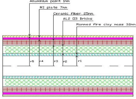
Refractory lining (1) was used by Purshottam Kumar in his experimental evaluations with the following specifications
(a) Installation of Ceramic fiber blanket of thickness 25.0 mm to reinforce the insulation and further reduce the heat losses from exchanger.
(b) The brick lining was done using alumina bricks of AL2O3 up to thickness of 60mm.
(c) The ramming with ramming mass consisting of 25% quartz and 75% fire clay up to thickness of 40.0 was done.
For present experimental evaluation, the following changes in refractory brick lining (2) are carried out to reduce the heat losses from furnace shell and increase furnace life.
a. Aluminum paint coating: The outer surface of furnace shell which remains exposed to atmosphere is painted with metallic aluminum paint of thickness 1mm. as aluminum paint has lowest emissivity among all available paintswhich drastically reduces the heat losses from furnace shell, and increases the utilization of heat inside the furnace and thus reduces the energy consumption.
b. Ceramic fibre blanket—These blankets have Excellent thermal stability, High resistance to burning, Low thermal conductivity.(0.09w/m0k), Low heat storage, Low shrinkage, and Convenience in installing
c. High alumina brick lining—Instead of rammed monolithic silica brick lining, the high alumina brick lining (70% Al2O3+2.5%Fe2O3) which gives an excellent operational life is used with the following technical
TABLE IV. TECHNICAL SPECIFICATIONS OF HIGH ALUMINA BRICKS
d. Special ramming mass- After few heats the ramming mass is repaired and patching is done. The special ramming mass consists of 70%Al2O3+1.0 %Fe2O3 and balance fire clay
For this new lining (2) the heat losses occur from inner surface to outermost surface as shown in figure 1.
Fig. 1. Front view of layout of lining 2
Heat losses from furnace shell with lining (2)- The heat lossesfrom furnace shell depends uponresistance to heat flow.The comparison of heat losses from furnace shell with two different linings--(1) Without aluminum
SN Parameters Particulars
1 Type High alumina
2 Raw material base Calcinated bauxite
3 Maximum service temperature 1500 0C
4 Reversible thermal expansion 0.65 at1000 0C
5 Chemical composition
(a) Al2O3
(b) SiO2
(c) Fe2O3
(d)TiO2
(e) CaO
70%
19.30%
2.5%
3.75%
1.40%
6 Bulk density 2.65-2.66 g/cc
7 Apparent porosity 21%-23%
8 Cold crushing strength 600-680 kg/cm2
9 Thermal conductivity (k)
(a) At 4000C
(b) At 6000C
(c) At 8000C
1.39 kcal/m/hr/0C
1.42 kcal/m/hr/0C
paint, monolithic silicabrick lining andrammed silica mass, and (2) With aluminum paint,ceramic fiber blanket, high alumina brick lining, and rammed fire clay mass, withproper installation,is shown in table V.
TABLE V. COMPARISON OF HEAT LOSSES (KW/M2) FROM FURNACE SHELL WITH TWO DIFFERENT LININGS
The average percentage reduction in heat losses is 42.50%-
The graphical representation ofComparison of heat losses from furnace shell with lining 1(without aluminum paint) andwith lining 2(with aluminum paint) is shown in fig 2.
Fig. 2.Graphical representation of comparative heat losses from furnace shell with two different linings
3.1 Further Experimental Investigations
After replacing the combustion equipment and refractory brick linings as explained in preceding sections, the following experimental investigations are carried out to see the effect of identified parameters on the
performance of rotary furnace.
(1) Effect of rotational Speed on energy consumption and performance of Furnace. (2) Effect of rotational speed on Emission level.
(3) Effect of 20% excess air on flame temperature, melting rate, & specific fuel consumption. (4) Effect of 10% excess air flame temperature, melting rate, & specific fuel consumption. 3.1.1 Effect of Rotational Speed on energy consumption and performance of Furnace-
The rotation of furnace is very important input parameter. If rotation is high the time of contact between charge and heated refractory will be very less consequently, the rate of heat transfer between the charge and refractory
S.N Tempe
rature0C
Heat losses lining (1) without
aluminum paint, silica lining &
rammed silica mass.
Heat losses Lining (2) with aluminum paint, ceramic fiber
blanket high alumina brick lining, rammed fireclay mass.
Percentage (%)
reduction in heat losses
1 500C 5.87 3.37 42.58
2 1000C 5.48 3.15 42.51
3 1500C 5.40 3.15 41.66
4 2000C 4.95 2.82 43.00
5 2500C 4.78 2.72 43.09
will be very low. To study the effect of rotational speed the investigations have been made between 0.8 to 2.0 rpm.
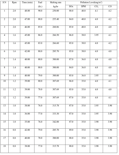
TABLE VI. EFFECT OF ROTATIONAL SPEED ON FUEL CONSUMPTION MELTING RATE & EMISSION LEVEL
WITH 10% BLENDING OF BIO-FUEL AND LDO
S.N Rpm Time (min) Fuel
(lit.)
Melting rate
kg/hr
Pollution Level(mg/m3)
SOx SPM CO2 CO
1 2.0 48.00 90.0 250.00 88.0 40.0 4.1 4.2
2 2.0 47.00 88.0 255.40 84.0 40.0 4.0 4.2
3 2.0 46.00 85.0 260.86 85.0 40.0 4.0 4.0
4 1.6 45.00 86.0 266.50 86.0 38.0 3.95 4.1
5 1.6 45.00 83.0 266.60 85.0 38.0 4.0 4.2
6 1.6 42.00 80.0 285.70 85.0 38.0 4.0 4.0
7 1.4 40.00 80.0 300.00 87.0 36.0 4.0 4.0
8 1.4 40.00 80.0 300.00 84.0 36.0 4.0 4.0
9 1.4 40.00 79.0 300.00 85.0 36.0 3.95 4.0
10 1.2 39.00 80.0 307.69 86.0 35.0 4.0 4.1
11 1.2 39.00 78.0 307.69 85.0 35.0 4.0 4.0
12 1.2 39.00 77.0 307.69 87.0 35.0 4.0 4.1
13 1.0 38.00 76.0 315.78 87.0 35.0 3.95 3.90
14 1.0 36.00 77.0 333.30 87.0 35.0 3.95 3.90
15 1.0 35.00 76.0 342.00 87.0 35.0 3.90 3.90
16 0.8 42.00 79.0 285.70 89.0 35.0 3.90 3.90
17 0.8 40.00 78.0 300.00 88.0 35.0 3.90 3.90
The computation of results of Experimental investigations (1)-Effect of rotational speedon annual energy savings, fuel cost, and annual production are calculated below -
(i)The effect of rpm on annual energy saving--
At 2.0 rpm specific fuel consumption is 0.425 liter/kg At 1.0 rpm specific fuel consumption is 0.38 liter/kg
Saving in fuel consumed in liters/kg = (0.425-0.380) =0.045 liters/kg. For one heat of 200.0 kg = 200x0.045litres =9.0 liters/heat
6 heats per day (at1 rpm) =9x6= 54.0litres/day. Assuming 25 days /month=25x54.0=1350 liters/month. The annual saving= 12x1350.0litres=16200 liters =16.2 kliters
The annual saving in energy consumption=16.2kliters x9.9047 Kwh/liter =16045614 Kwh==1.604x10⁵ Kwh Reducing rpm from 2.0 to1.0, the annual energy savings
=1.604x10⁵ Kwh
(ii) The effect of rpm on fuel cost—
(a) The present L.D.O. cost = Rs 40.00/ litre.and cost of jatropha is Rs75.00/litre.Taking combination of LDO and 10% jatropha,the approximate cost of the fuel is considered as Rs50/litre
(b) The annual savings= 16200 litre x Rs 50/litre =Rs 8.10 Lakhs. (iii)The effect of rpm on annual production-
(a) At 2.0 rpm-No. of heats/day =5, production /heat =200 kg, per day=1000 kg, Per annum =300x1000kg= 300 tonnes
(b) At 1.0 rpm -No. of heats =6, production /heat =200.0 kg, per day =1200.0 kg, per annum=300x1200kg= 360.0 tonnes
The results of above experimental investigations of reducing rpm from 2.0 to 0.8 are studied and then the optimal values are obtained for energy consumption and emission level of pollutants. These values are obtained at 1.0 rpm. The improvement in performance of furnace by changing rpm from 2.0 to 1.0 is shown in table VII.
SN Parameters Absolute reduction Percentage Reductions/
improvements
2.0rpm 1.0 rpm
1 (a)Melting time(minutes) 46 35 23.91%
(b)Minimum Fuel consumption(liters) 85 76 10.58%
(c)Specific fuel consumption(lit/kg) 0.425 0.380 10.58%
(d)Energy consumption in melting (kwh/tonne) 4110.45 3763.78 8.43 %
TABLE VII. IMPROVEMENT IN PERFORMANCE OF FURNACE BY CHANGING RPM FROM 2.0 TO 1.0
During operation of furnace under existing conditions it was observed that (i) The atmospheric air is directly being supplied to burner (without preheating) for combustion of oil which leads to its incomplete combustion.
(ii) The 30% excess air was supplied which leads to higher combustion volume and increases the air fuel ratio.These both factors increase the oil consumption, resulting into more energy consumption.
Excess air- Minimum amount of air, which is required for complete combustion of fuel, is calculated theoretically, but always excess air is used because whole of the air supplied for combustion purpose does not come in contact with the fuel completely and as such a portion of fuel may be left unburnt. Therefore, an additional amount of air is required to be supplied for complete combustion of fuel.
Effect of excess air on performance of furnace--The role of excess air is more dominating as explained in the following section.
For maximum flame temperature and melting rate the optimization of excess air and preheat is required. To maintain the optimum flame temperature, the supply of excess air and its preheating is to be adjusted. An optimum excess air has to be used because more excess air will increase the combustion volume and reduce the flame temperature and exact amount of air will exceed the temperature beyond safe metallurgical limits which will reduce the life of refractory and furnace shell.
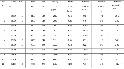
3.1.2 Experimental investigations —Effect of 20.0% excess air on flame temperature, time, fuel, melting rate,
& specific fuel consumption.
Again experiments were repeatedby reducingexcess air to 20%,with compact heat exchanger, rotating furnace at optimal rotational speed 1.0 rpm, preheating LDO up till 70.00C. The observations taken during experiment are given in table VIII.
(f) Emission levels- (mg/m3)
1.SOx
2 SPM
3 CO2
4 CO 90 40 4.00 4.00 88 35 3.90 3.90 0.02% 2.22% 12.50% 12.50%
2 (a)Melting rate(kg/hr)
(b)No. of heats per day(200 kg)
260.86 5 342 6 31.10% 20%
3 Annual savings
(a)Annual energy consumption
(b)Annual fuel (liters)
(c)Annual fuel cost
1.6x10⁵ kwh
16.2 k liters
Rs.8.10 lakhs
TABLE VIII. EFFECT OF 20% EXCESS AIR ON FLAME TEMERATURE, TIME, FUEL, MELTING RATE &
SPECIFIC FUEL CONSUMPTION
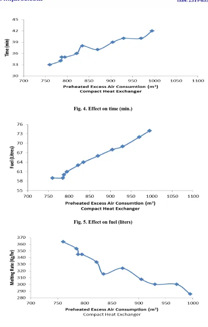
The above results are graphically represented in figures 3, 4, 5 & 6.
Fig. 3. Effect on flame temperature0C
Heat
No
Flame
TempC
RPM Time
min.
Fuel
liters
Melting
rate
(kg/hr)
Specific
fuel cons
liter/kg
Preheated
excess air
cons.m3
Preheated
excess air
%
Preheated
excess air temp.C
1 1510.0 1.0 42.00 74.0 285.7 0.370 995.0 30.1 304.0
2 1530.0 1.0 40.00 72.0 300.3 0.360 970.0 25.5 316.0
3 1540.0 1.0 40.00 69.0 300.3 0.345 930.0 20.3 320.0
4 1545.0 1.0 39.00 68.0 307.6 0.340 905.0 20.1 329.0
5 1550.0 1.0 37.00 66.0 324.3 0.330 870.0 20.2 332.0
6 1568.0 1.0 38.00 64.0 315.7 0.33 835.0 19.9 340.0
7 1570.0 1.0 36.00 63.0 333.3 0.315 822.0 20.0 348.0
8 1578.0 1.0 35.00 61.0 344.82 0.305 795.0 19.9 370.0
9 1580.0 1.0 35.00 60.0 344.82 0.300 788.0 20.1 378.0
10 1590.0 1.0 34.00 59.0 353.35 0.295 785.0 20.0 385.0
Fig. 4. Effect on time (min.)
Fig. 5. Effect on fuel (liters)
Figs 3,4,5 & 6 --The graphical representation of Effect of 20.0% excess air rotating furnace at optimal speed of 1.0 rpm, on flame temperature, time, fuel and melting rate.
Effect of 10.0% excess air on flame temperature,time, fuel, melting rate, and specific fuel
consumption-Experiments wererepeated reducing excess air to 10.0%, under similar conditions. The observations taken during experiment are given in table IX.
TABLE IX. EFFECT OF 10% EXCESS AIR ON FLAME TEMERATURE, TIME, FUEL, MELTING RATE & SPECIFIC
FUEL CONSUMPTION
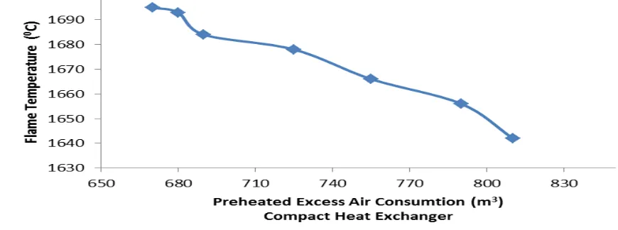
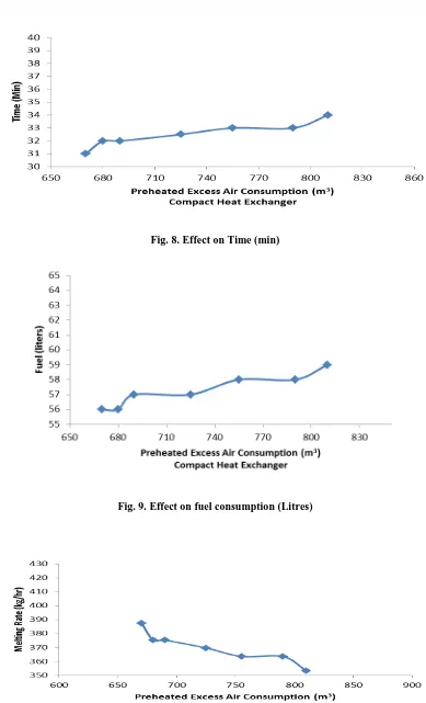
The above results are graphically represented in the form of curves in the figure 7, 8, 9 & 10.
Fig. 7. Effect on Flame temperature
S.No FlameTem
p0C.
Rp
m
Time
min.
Fuel
liters
For
200 L
Melting
rate kg/hr
Specific
fuelcons
liter/kg
Preheatedair
cons. (m3)
Preheated
air%
Preheated air temp.C
1 1642.0 1.0 34.00 59.0 353.35 0.295 810.0 11.4 386.0
2 1656.0 1.0 33.00 58.0 363.63 0.285 790.0 11.3 395 .0
3 1666.0 1.0 33.00 58.0 363.63 0.282 755.0 10,0 396.0
4 1678.0 1.0 32.50 57.0 369.68 0.285 725.0 10.6 397.0
5 1684.0 1.0 32.00 57.0 375.23 0.285 690.0 10.1 403.0
6 1693.0 1.0 32.00 56.0 375.23 0.280 680.0 10.1 408.0
Fig. 8. Effect on Time (min)
Fig. 10. Effect on melting rate (kg/hr)
Figs.7,8,9 & 10--Effect of 10.0% excess air at optimal rotational speed 1.0 rpm on flame temperature, time, fuel, andmelting rate.
It is very clear thatusing compact heat exchanger and gradually reducing excess air,not only increases the flame temperature from 1510.0 to 1695.0°C, and melting rate from 285.70 kg/hr to 387.50 kg/hr but also reduces the fuel consumption to 0.280 litre/kg of molten metal produced.
Energy consumption-the effect of reducing excess air initially to 20.0% and then to 10.0%,rotating furnace at optimal rotational speed 1.0 rpmonmelting rate and fuel consumption are shown in table and on energy consumption in table X.
TABLE X. MELTING RATE & FUEL CONSUMPTION UNDER DIFFERENT CONDITIONS OF EXCESS AIR
S.No Parameter 20.0%-excess air with
compact heat exchanger,
rotational speed of 1.0 rpm,
10.0%-excess air
with compact heat
exchanger, rotational
speed of 1.0 rpm,
1 Melting rate kg/hr. 363.6 387.0
2 Fuel used in
melting
(Litres/tone)
290.0 280.0
And on energy consumptions (kwh/tonne) is shown in table XI.
TABLE XI. ENERGY CONSUMPTION UNDER DIFFERENT CONDITIONS OF EXCESS AIR
S.No Parameter 20.0%-excess air 10.0%-excess air
1 Melting only 2872.36 2773.31
2 Fuel combustion unit (Reillo
burner)
5.128 4.818
3 Plant & Equipment 22.566 21.199
4 Pollution controlequipment 12.309 11.563
5 Shot blasting m/c 7.460 7.460
Total energy consumption kwh 2919.81
(2920.00)
2818.348
Comparison of energy consumptions—When furnace wasrotated at optimal rotational speed 1.0rpm,withexcess air 10.0%,preheated up to 412.00C,using compact heat exchanger, in melting only, the energy consumption is reduced to 2773.31kwh/tonne and total energy consumption to 2819.00 kwh/tonne
IV.
CONCLUSION
(1) The new Refractory brick lining (2) isfound significant for rotary furnace to reduce the energy consumption, maximum utilization of heat inside the furnace, reducing heat losses, and increasing life of furnace.
(2) It is concluded from this Experimental Investigation that using modified heat exchanger with changed lining(2) and LDO with 10%bio-fuel,optimal rotational speed is 1.0 rpm. It is very clear that rotational speed affects the melting rate, energy consumption and emission level of pollutants. During operation of furnace under existing conditions it is also observed that
(a) All the pollutants are within the range of CPCB norms
(b) Only 10.0% excess air, preheated up to 4100C,is to be supplied for complete combustion of fuel.
(c) With above input parameters the energy consumption in melting is reduced to 2774.00 Kwh/tonne and total energy consumption to 2819.00Kwh/tonne.
(3) It is concluded that reducing rotation of furnace from 2 to 1rpm the annual saving in fuel cost of Rs. 8.10 lakhs is obtained which is a significant amount. Also annual change in rpm has significant effect on annual production.
(4) It is also clear that using compact heat exchanger and gradually reducing excess air, not only increases the flame temperature from 1510.0 to 1695.0°C, and melting rate from 285.70 kg/hr to 387.50 kg/hr but also reduces the fuel consumption to 0.280 litre/kg of molten metal produced.
Hence, it can be concluded that a Rotary furnace with the suggested modifications can be used as furnace for melting iron in an eco-friendly environment using energy within the limits of TERI. Hence, Rotary Furnace with the above modifications will be a boon for the foundry industry of Agra and India at large.
V.
ACKNOWLEDGMENT
We gratefully acknowledge Most Revered Prof. P.S.Satsangi, Chairman, Advisory Committee on Education, Dayalbagh Educational Institute, Agra for his constant support and inspiration.
REFERENCES
[1] Bandopadhaya, A., Rao, Ramchandra, P., “ Envoronmental polution from cast iron foundries, The probles
amd strategies for their migration”, A paper presented at workshop on, Iron foundry energy scenario in raw material and technology, Organized by development commisioner for iron and steel Calcutta, 1994.
[3] Bandopadhaya, A., Dutta, A., and Gupta, K.N., 1996, “Energy Environment and Resource Management”,
Proceedings of Seminar on Indian Mineral Industries, 1996, pp. 51-63.
[4] Banerjee, S.N., 1995, “ Clean Air and control of pollution is a National requirement”, Indian Foundry
Journal, 1995.
[5] Datta, S.K., and Cele, A.B., “ Induction melting practices: Basic aspects and recent trends”, Indian Foundry
Journal, 1995, pp 17-22.
[6] Landge, K.A., Kolhatkar, “ Gas cleaning system in foundry industries”, Indian Foundry Journal, 1995. [7] Maiti, B.R., “ Detection and monitoring techniques for enviromental pollution from foudries”, Indian
Foundry Journal, 1995, pp 25-29.
[8] Mohammad, N.S., Sunder, M., Angelo, P.C., and Radha Krishnan, S., “ Pollution control in electric
furnaces and oil fired furnaces”, Indian Foundry Journal, 1998, pp. 37-40.
[9] Panigrahi, S.C., “ Some aspects of pollution in foundries”, Indian Foundry Journal, 1995, pp. 1-9.
[10] Parthsarthy, T.C., and Kumar, T.S.V., “Air pollution control in foundries”, Indian Foundry Journal, 1998,
pp. 115-121.
[11] Raizada, R.K., “The role of induction furnaces in development of casting in pollution free atmosphere”,
National seminar on Pollution control Measures, Calcutta, 1993.
[12] Selby, T.R., “Foundry management and technology”, Indian Foundry Journal, 1974, p 102. [13] Tiwari, S.N., “On status of Indian foundry industry”, Indian Foundry Journal, 1998, pp. 17-20.
[14] Kumar Purshhotam.,“An Eco-friendly and affordable melting technique for CI foundries”, A Ph.D thesis submitted to Dayalbagh Educational Institue, 2014.
B
IOGRAPHYDilip Kumar is a Research Scholar in Mechanical Engineering Department, Faculty of Engineering, DEI, with 5 years’ experience in teaching and research. He has pursued B.Sc (Engg.) in Mechanical Engineering and M.Tech in Engineering Systems from Dayalbagh Educational Institute. Presently he is working on sustainability, operational excellence in foundries in eco-friendly environment using Six Sigma techniques.
Prof. Ranjit Singh is an Emeritus professor in Mechanical Engineering Department with more than 43 years of experience in teaching and
technical sessions at various conferences and workshops in India and Abroad. He has visited number of countries and is doing collaborative research with industries and institutions of abroad. Professor Ranjit Singh has also won several awards/certificates of merit/appreciation/honours which include University Gold Medal for First Position in ME in production Engineering from IITRoorkee, Most coveted “P. Banerjee Medal” for the best technical paper in Indian Foundry Journal, 2000 and “prestigious Ramanna Fellowship” for the year 2006 by the Dept. of Science and Technology, Government of India. Prof. K Arumugam National award for innovative work in engineering & technology was awarded in recognition of outstanding contribution in the area of foundry engineering by ISTE in 2012. He is a life member of the Institution of Engineers (India) and the Systems Society of India. Presently he is working on a UGC sponsored project under Emeritus fellowship.