THE R5 PROCEDURES FOR ASSESSING THE HIGH TEMPERATURE
RESPONSE OF STRUCTURES: CURRENT STATUS AND RECENT
DEVELOPMENTS
David W Dean, Louise C Allport and Marc J Chevalier
Assessment Technology Group, EDF Energy, UK
ABSTRACT
The R5 procedures have been developed within the UK power generation industry to assess the integrity of nuclear and conventional plant operating at high temperatures. They are routinely used by EDF Energy for the assessment of metallic components in its Advanced Gas-Cooled Reactor (AGR) fleet that typically operate at temperatures in the range 470-650oC. R5 is currently maintained by EDF Energy in the UK under an industrial collaboration that also involves AMEC Foster Wheeler, Rolls-Royce, Atkins and the Australian Nuclear Scientific and Technical Organisation (ANSTO). This industrial collaboration is augmented by related university research and development work carried out by the EDF Energy High Temperature Centre, involving Imperial College London and Bristol, Oxford, Manchester, Open, Strathclyde, Loughborough, and Korea universities.
This paper first summarises the current status of the R5 procedures and outlines the R5 Volume 2/3 procedure for assessing creep-fatigue crack initiation in initially defect-free components. Then two significant recent developments in R5 Volume 2/3 are described, both of which are highly relevant to real instances of creep-fatigue cracking that have been observed in high temperature austenitic AGR plant components. Finally, planned ongoing and future developments of the procedures are briefly outlined.
INTRODUCTION
EDF Energy’s R5 Assessment Procedure for the High Temperature Response of Structures (EDF Energy, 2014) is an established methodology, which is frequently used in safety cases for structural integrity assessments of components in the UK’s Advanced Gas cooled Reactors (AGRs), which operate in the creep range. The procedures are also relevant to conventional power generating plant and high temperature plant outside the power generation industry. Ongoing development of the R5 procedure by EDF Energy is carried out in collaboration with industrial partners AMEC Foster Wheeler, Rolls-Royce, Atkins and the Australian Nuclear Scientific and Technical Organisation (ANSTO). This industrial collaboration is augmented by related university research and development work carried out by the EDF Energy High Temperature Centre, involving Imperial College London and Bristol, Oxford, Manchester, Open, Strathclyde, Loughborough, and Korea universities.
Assessment of the safe lifetime of components, operating at temperatures that are sufficiently high for creep to be a potential failure mechanism, may be divided into two stages. The first is assessment of the time or cycles for cracking to occur in the initially defect-free component as a result of combined creep and fatigue damage, which can be assessed using the R5 Volume 2/3 procedure. The second is assessment of the time or cycles for a crack in the component to grow to a critical size as a result of creep and fatigue mechanisms, which can be assessed using the R5 Volume 4/5 procedure.
instances of creep-fatigue cracking that have been observed in high temperature austenitic AGR plant components (Dean and Johns, 2015). Finally, planned ongoing and future developments of the procedures are briefly outlined.
CURRENT STATUS OF THE R5 PROCEDURES
The R5 procedures provide an assessment of the continuing integrity of a component, where the operating lifetime might be limited by one of the following mechanisms:
(1) excessive plastic deformation due to a single application of a loading system, (2) creep rupture,
(3) ratchetting or incremental plastic collapse due to a loading sequence, (4) excessive creep deformation enhanced by cyclic load,
(5) initiation of cracks in initially defect-free material by creep and creep-fatigue mechanisms,
(6) the growth of cracks by creep and creep-fatigue mechanisms.
R5 is an established methodology, first produced about 25 years ago (Nuclear Electric, 1990). In 2003, the former Volumes 2 and 3 of R5 were combined into a single procedure for assessing defect-free structures and the former Volumes 4 and 5 were combined into a single procedure for assessing defects in structures (British Energy, 2003). There are now 5 volumes in R5 in total:
Volume 1: The overview
Volume 2/3: Creep-fatigue crack initiation procedure for defect-free structures Volume 4/5: Procedure for assessing defects under creep and creep-fatigue loading Volume 6: Assessment procedure for dissimilar metal welds
Volume 7: Behaviour of similar weldments: guidance for steady creep loading of ferritic pipework components
Volume 1 provides an overview, which indicates the overall scope and restrictions of R5 by reference to the other volumes, provides a route for following the detailed procedures given elsewhere in R5, and compares R5 with other approaches. Volumes 6 and 7 are essentially specialised applications of the creep-fatigue damage calculations of Volume 2/3 and the creep and creep-fatigue crack growth calculations of Volume 4/5, respectively, to particular weldments and operating conditions found in AGRs.
R5 VOLUME 2/3
As noted above, R5 Volume 2/3 uses a ductility exhaustion model to assess creep damage occurring during dwell periods in creep-fatigue cycles. The creep damage per cycle, dc, is then given by
dt ) ductility affecting
factors ( d
h
t
0 f
c c
∫
ε
ε
= & (1)
where ε&c is the instantaneous equivalent creep strain rate during the dwell period and εf is the appropriate creep ductility taking account of the effects of stress state and any factors, such as creep strain rate, stress magnitude and temperature, that affect ductility. Previous versions of R5 Volume 2/3, including Issue 3 Revision 001 (EDF Energy, 2012), included two options for calculating creep damage.
Option 1 - use of a constant lower shelf ductility
The calculation of creep damage is simplified if it is pessimistically assumed that the creep ductility is independent of strain rate and equal to the lower shelf ductility, εL, suitably factored to take account of stress state and denoted εL. Option 1 can be used to provide a pessimistic estimate of creep damage providing an accurate or pessimistic estimate of creep strain accumulation during the dwell period can be determined.
Option 2 - use of strain rate dependent ductility
The Option 2 approach gives a lower estimate of creep damage than Option 1 as the creep ductility is analysed as a function of strain rate and stress state rather than pessimistically assuming a lower shelf ductility (which is independent of strain rate, but not stress state) as in Option 1. To use Option 2, it is therefore necessary to estimate the strain rates at all times during the dwell periods.
However, it has been shown that these ductility exhaustion approaches (Options 1 and 2 above) can lead to overly conservative predictions of creep damage for creep-fatigue cycles with either intermediate dwells or for peak dwells in cycles with low strain ranges (i.e. for cases involving lower start-of-dwell stresses). In addition, it was considered that the previous approach for assessing creep-fatigue damage in cases involving compressive dwells (which included estimation of a non-zero value of creep damage in compression) was not consistent with the physical damage processes occurring under these conditions. These limitations in the previous approaches provided the motivation for developing new, improved approaches for predicting creep damage, which are described later in this paper.
RECENT DEVELOPMENTS IN R5 VOLUME 2/3
R5 Volume 2/3 Issue 3 Revision 002 (EDF Energy, 2014) includes improved advice in the following areas:
(a) New advice on the treatment of compressive dwells and inclusion of the stress-modified ductility exhaustion approach as a new third option for estimating creep damage.
(b) A new approach for assessing creep-fatigue crack initiation in weldments, which involves replacing the previous Fatigue Strength Reduction Factors with Weld Strain Enhancement Factors and a Weldment Endurance Reduction.
(c) Updated advice on Ks factors (which are used in R5 to obtain material ratchet limits), including a new criterion for determining strain instability and a modified Ks curve for ½Cr½Mo¼V ferritic steels.
(d) Addition of a new multiaxial creep rupture model for Type 316H steel.
(e) Updates to reflect recent developments in extending the Bree problem to different loading scenarios (Bradford, 2012) and the use of direct methods, such as the Linear Matching Method (Chen et al., 2013), to demonstrate shakedown.
(f) Updates to reflect the current status of relevant constitutive models.
The following sections in this paper briefly summarise the first two significant developments related to improved methods for calculating creep damage and a new approach for assessing creep-fatigue crack initiation in weldments.
IMPROVED METHODS FOR THE CALCULATION OF CREEP DAMAGE
Treatment of Compressive Dwells
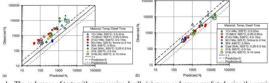
The physical understanding of creep cavitation mechanisms, which suggests that creep cavities can neither nucleate nor grow under compressive stresses, is inconsistent with the previous R5 advice for treating compressive dwells, which included estimation of a non-zero value of creep damage in compression. Nevertheless, the experimental evidence (EDF Energy, 2014; Spindler, 2008) shows that when only compressive dwells are present the effect on the creep-fatigue endurance can be significant. Thus it is necessary to increase the fatigue damage to take account of the observation that compressive dwells lead to reduced endurance. The new R5 Volume 2/3 approach for assessing compressive dwells assumes that the creep damage is zero, but the fatigue damage is increased by removing the nucleation phase of fatigue endurance (which is equivalent to conceding that a crack of size 0.02mm is present), leaving only the fatigue crack growth phase from 0.02mm to the initiating defect size, a0. Validation of this approach is shown in Figure 1, which compares the observed numbers of cycles to failure with those predicted.
10 100 1000 10000 100000
10 100 1000 10000 100000
Predicted Nf
O
b
s
e
rv
e
d
N
f
1Cr½Mo; 535°C; 0.5-2hrs 1CrMoV; 565°C; 0.05-0.5hrs 2¼Cr1Mo; 538°C; 0.5-1hrs 9Cr1Mo; 525°C; 5mins to 2 hrs 304; 649°C; 0.5hrs Cast 304L; 650°C; 0.25-0.5 hrs 316; 593°C; 0.5 hrs 316L(N); 600°C; 5-10 mins 1:1
Prediction/2 Predictionx2 Material; Temp; Dwell Time
(a)
10 100 1000 10000 100000
10 100 1000 10000 100000
Predicted Nf
O
b
se
rv
e
d
N
f
1Cr½Mo; 535°C; 0.5-2hrs 1CrMoV; 565°C; 0.05-0.5hrs 2¼Cr1Mo; 538°C; 0.5-1hrs 9Cr1Mo; 525°C; 5mins to 2 hrs 304; 649°C; 0.5hrs Cast 304L; 650°C; 0.25-0.5 hrs 316; 593°C; 0.5 hrs 316L(N); 600°C; 5-10 mins 1:1
Prediction/2 Predictionx2 Material; Temp; Dwell Time
(b)
It can be seen in that the new approach (Figure 1(b)) gives a better prediction of the number of cycles to failure than the previous approach, which tends to be overly conservative (Figure 1(a)). Although the new approach does not explicitly take into account the physical processes that occur during a compressive dwell, such as; (i) increased mean stress, (ii) increased oxidation, (iii) increased hysteresis energy and (iv) thermal softening, it is anticipated that these processes, particularly effects of oxidation, would significantly affect the fatigue crack nucleation phase.
The Stress-Modified Ductility Exhaustion (SMDE) Approach
The stress-modified ductility exhaustion (SMDE) approach has been included as a new third option for calculating creep damage. The creep damage per cycle, dSMc , for the Option 3 SMDE approach is given by
dt ) T , , ( d
h
t
0 f in in SM
c
∫
σ ε ε
ε =
& &
(2)
where ε
(
ε ,σ,T)
in
f & is the inelastic strain at failure at the appropriate temperature, T, as a function of both
the inelastic strain rate, ε&in, and the stress, σ. A different nomenclature for the SMDE approach is used in equation (2) for consistency with the treatment of ductility data for this approach, which considers that both time independent (monotonic) plastic strains and time dependent creep strains (that are collectively termed inelastic strains) contribute to failure in creep tests that are used to derive ε ( , ,T).
1 in
f ε& σ However, the inelastic strain that accumulates during a strain or displacement controlled dwell under creep-fatigue conditions is time dependent and is traditionally defined as creep strain. Thus the inelastic strain rate, during the dwell of a creep-fatigue cycle, is the same as that used in the existing Option 1 and 2 approaches for calculating creep damage. Cyclic plastic strains are not included in either the numerator or the denominator of equation (2).
It has been shown experimentally (Spindler, 2004a; Spindler, 2005a; Spindler, 2006; Spindler, 2008; Spindler and Payten, 2011) that the uniaxial creep ductility of austenitic and ferritic steels can often be represented by
σ ε
ε =
ε n1 −m1
c 1 1 , U f
T P exp A
MIN & (3)
where A1, n1, m1 and P1 are material constants. It should be noted that the upper shelf ductility, εU, is necessary to analyse creep data which include high ductility constant rate and creep tests that fail by necking followed by ductile transgranular failure, either by shear at 45° or by ‘cup and cone’. However, this type of failure can not physically occur during a strain controlled creep-fatigue cycle and the upper shelf term in equation (3) is removed when predicting creep damage under creep-fatigue conditions. The SMDE approach in R5 Volume 2/3 also covers multiaxial states of stress (EDF Energy, 2014; Spindler, 2004b) although discussion here is restricted to application of the approach to uniaxial creep-fatigue tests.
The SMDE approach has previously been compared with the time fraction and R5 ductility exhaustion approaches by assessing creep-fatigue data for a range of materials using the same stress relaxation and fatigue data (Spindler, 2004a; Spindler, 2005a; Spindler, 2005b; Spindler, 2006; Spindler, 2008; Spindler and Payten, 2011). Figure 2 shows best estimate and upper bound creep-fatigue damage predictions for creep-fatigue tests on a range of austenitic materials using the existing Option 2 (strain rate dependent) ductility exhaustion approach in R5. Figure 3 shows equivalent predictions based on the new Option 3 SMDE approach.
lower start-of-dwell stresses. Figure 3 shows that that the SMDE approach removes this unrealistic conservatism and produces more accurate best estimate damage predictions and gives sensibly conservative upper bound damage predictions.
Creep Damage, Dc
0.01 0.1 1 10
F a ti g u e D a m a g e , Df 0.01 0.1 1 10 Linear Interaction x2 /2
Type 316H at 570°C Peak Dwells Cast 304L at 650°C Peak Dwells Cast 304L at 650°C Intermediate Dwells Type 347 Weld at 650°C Peak Dwells Type 347 Weld at 650°C Intermediate Dwells Type 321 at 650°C Peak Dwells
Creep Damage, Dc
0.01 0.1 1 10 100
F a ti g u e D a m a g e , Df 0.01 0.1 1 10 Linear Interaction x2
Type 316H at 570°C Peak Dwells Cast 304L at 650°C Peak Dwells Cast 304L at 650°C Intermediate Dwells Type 347 Weld at 650°C Peak Dwells Type 347 Weld at 650°C Intermediate Dwells Type 321 at 650°C Peak Dwells
(a) Best estimate (b) Upper bound
Fig. 2 Best estimate and upper bound creep-fatigue damage for austenitic steels based on the Option 2 (strain rate dependent) ductility exhaustion approach in R5 Volume 2/3
Creep Damage, Dc
0.01 0.1 1 10
F a ti g u e D a m a g e , Df 0.01 0.1 1 10 Linear Interaction x2 /2
Type 316H at 570°C Peak Dwells Cast 304L at 650°C Peak Dwells Cast 304L at 650°C Intermediate Dwells Type 347 Weld at 650°C Peak Dwells Type 347 Weld at 650°C Intermediate Dwells Type 321 at 650°C Peak Dwells
Creep Damage, Dc
0.01 0.1 1 10 100
F a ti g u e D a m a g e , Df 0.01 0.1 1 10 Linear Interaction x2
Type 316H at 570°C Peak Dwells Cast 304L at 650°C Peak Dwells Cast 304L at 650°C Intermediate Dwells Type 347 Weld at 650°C Peak Dwells Type 347 Weld at 650°C Intermediate Dwells Type 321 at 650°C Peak Dwells
(a) Best estimate (b) Upper bound
NEW APPROACH FOR ASSESSING WELDMENTS
This section briefly outlines the new Volume 2/3 Appendix A4 approach for assessing creep-fatigue initiation in weldments1, which seeks to remove known conservatisms which exist when using the FSRF approach as previously discussed.
The new approach separates the previous FSRF into the following two components:
(i) the Weld Strain Enhancement Factor (WSEF), which accounts for strain enhancement due to the weldment geometry (if applicable) and the material mis-match between weldment zones, and; (ii) the Weld Endurance Reduction (WER), which accounts for the fatigue endurance reduction due to
the presence of small imperfections (e.g. inclusions, porosity etc.) in the weldment constituent materials.
In addition, the new approach has been simplified by adopting a single route for both dressed and undressed (or as-welded) weldments.
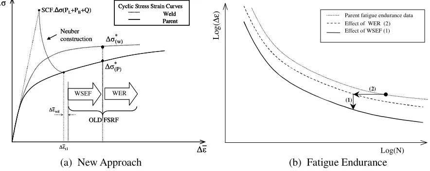
The main steps in the modified procedure are illustrated in Figure 4(a). The first step is to perform a shakedown analysis (e.g. using finite element methods) and then to derive the linearised elastic stress range based on the primary and secondary stress ranges, ∆σ(PL +PB +Q). This is used, in conjunction with the Neuber construction, to derive the corresponding elastic-plastic strain range using the parent material cyclic stress-strain curve. Also, the elastic-plastic strain range is enhanced by an additional strain range, ∆εvol, to take into account the difference in Poisson’s ratio between elastic and inelastic conditions. A WSEF is then applied to the elastic-plastic strain range, which, in conjunction with the WER, is used to derive the number of cycles to crack initiation in the fatigue damage calculation. This compares with the use of the FSRF in the previous route which is also shown in Figure 4(a).
WSEF SCF.∆σ(PL+PB+Q)
Neuber construction
Cyclic Stress Strain Curves Weld Parent
t1
ε ∆
σ ∆
ε ∆
vol ε ∆
* (w)
∆σ
* (P)
∆σ
WER
OLD FSRF WSEF SCF.∆σ(PL+PB+Q)
Neuber construction
Cyclic Stress Strain Curves Weld Parent Cyclic Stress Strain Curves
Weld Parent
t1
ε ∆
σ ∆
ε ∆
vol ε ∆
* (w)
∆σ
* (P)
∆σ
WER
OLD FSRF
L
o
g
(
∆
ε
)
Log(N) Parent fatigue endurance data
Effect of WER (2) Effect of WSEF (1)
(1) (2)
(a) New Approach (b) Fatigue Endurance
Fig. 4 Schematic of (a) new approach showing split of FSRF into WSEF and WER and (b) the effect of the WSEF and WER on parent fatigue endurance
For fatigue life predictions, the modified procedure is broadly similar to the previous route, since the combination of the WER and the WSEF in the modified route, i.e. steps (2) and (1), respectively, in
1
Figure 4(b), corresponds to the FSRF. The WER takes account of the reduction in fatigue endurance due to the presence of small imperfections (e.g. inclusions, porosity, etc.) in the weldment constituent materials and is evaluated by removing the nucleation phase of fatigue endurance (which is equivalent to conceding a small crack of depth 0.02mm), leaving only the fatigue crack growth phase from 0.02mm to the initiating defect size, a0. WSEF values have been derived from the same weldment database as FSRF values, but have been derived relative to the reduced endurance curve (i.e. the baseline parent fatigue curve factored by the WER, as shown by the intermediate dashed fatigue curve in Figure 4(b)); consequently, for fatigue life predictions, the combination of the WSEF and WER in the new procedure broadly corresponds to the FSRF used in the previous route. The WSEFs have been derived such that the parent mean fatigue curve, factored by the WSEF and WER, provides a mean best fit to the weldment fatigue data assuming a log normal distribution of fatigue life (O’Donnell, 2005; Smith et al., 2008).
In the modified route, either the parent or weld metal cyclic stress-strain curve is used, depending on the assessment location, as illustrated in Figure 4(a), to determine the appropriate stress ranges, ∆σ*(P) or
. *
) w (
σ
∆ These are then used to calculate the appropriate start-of-dwell stress, σ0.
As previously discussed, the use of FSRFs in the previous approach resulted in overly conservative creep damage predictions as the FRSF included the effect of both weld endurance reduction (WER) and a weld strain enhancement factor (WSEF). In the previous approach for undressed welds, the FSRF was used to calculate both the fatigue damage and the stress range used to estimate the start-of-dwell stress. However, in the new approach whilst the fatigue damage is calculated using both the WER and WSEF (which is broadly equivalent the previous FSRF), it is only the WSEF that is used to calculate the cyclic stress range that is used to estimate the start-of-dwell stress, resulting in a lower start-of-dwell stresses and hence less creep damage than was obtained using the previous route.
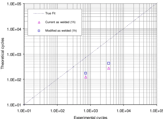
Figure 5 shows that the modified procedure results in improved (but still conservative) predictions of the endurance of creep-fatigue tests on undressed Type 1 weldments. Qualitatively similar results have also been obtained for other weldment types (Smith et al., 2008; Smith et al., 2014).
1.0E+01 1.0E+02 1.0E+03 1.0E+04 1.0E+05
1.0E+01 1.0E+02 1.0E+03 1.0E+04 1.0E+05
Experimental cycles
T
h
e
o
re
ti
c
a
l
c
y
c
le
s
True Fit
Current as welded (1h)
Modified as welded (1h)
FUTURE DEVELOPMENTS OF THE R5 PROCEDURES
Future R5 development activities include:
• Further developments of the R5 Volume 2/3 approach for assessing weldments to account for differences in the behaviour of thick (multi-pass) and thin (1 or 2 bead) weldments to account for significantly lower levels of mis-match (and hence potentially lower WSEFs) in the latter case.
• Development of probabilistic R5 Volume 2/3 approaches, which can be used to manage the lifetime of structural systems, especially systems with multiple components such as boiler tubes (Bradford, 2015).
• Development of new methods to enable R5 Volume 2/3 assessments to be carried out for austenitic stainless steel components that have been carburised in AGR primary gas coolant (Chevalier, 2015).
• Derivation of Ks factors (which are used in R5 Volume 2/3 to obtain material ratchet limits) for a wider range of materials than are those for which explicit advice is currently available.
• Refinement of current advice in R5 Volume 4/5 for estimating the parameter C(t), which controls short-term creep crack growth under combined primary and secondary loading (Ainsworth et al., 2015).
• R5 Volume 4/5 predictions of creepcrack growth rely on the availability of appropriate creep crack growth data. Work is continuing to improve the understanding and interpretation of long-term creep crack growth tests carried being carried out on materials relevant to AGR plant components, noting that the longest test duration has now exceeded 100, 000 hours.
CONCLUDING REMARKS
This paper has summarised the current status of the R5 procedures and outlined the current R5 Volume 2/3 procedure. Two significant recent developments in R5 Volume 2/3 have then been described, both of which are highly relevant to real instances of creep-fatigue cracking that have been observed in high temperature austenitic AGR plant components.
The first of these is the development of improved methods for predicting creep damage. These include a new approach for assessing compressive dwells together with the inclusion of the stress-modified ductility exhaustion approach as a new third option for calculating creep damage. Assessments of creep-fatigue tests with have shown that these improved methods result in more accurate predictions of test endurances.
The second significant development is the new approach for assessing creep-fatigue crack initiation in weldments, which involves splitting the previous Fatigue Strength Reduction Factor (FSRF) into a Weldment Endurance Reduction (WER), which accounts for reduced fatigue endurance due to weld imperfections, and a Weldment Strain Enhancement Factor (WSEF). Assessments of weldment creep-fatigue features tests have shown that the modified approach results in more accurate, but still conservative, predictions of test endurances.
Finally, a number of future R5 development activities have been briefly outlined.
ACKNOWLEDGEMENT
REFERENCES
Ainsworth, R. A., Dean, D. W., Budden, P. J. and Hughes, D. G. H. (2015). “Estimation of the parameter controlling short-term creep crack growth under combined primary and secondary loading”, Proc SMiRT 23, Manchester, UK.
Bradford, R. A. W. (2012). “The Bree problem with primary load cycling in-phase with the secondary load”, Int J Pres Ves Piping, 99-100, 44-50.
Bradford, R. A. W. (2015). “Application of probabilistic assessments to the lifetime management of nuclear boilers in the creep regime”, Proc SMiRT 23, Manchester, UK.
British Energy (2003). “R5: Assessment procedure for the high temperature response of structures”, Issue 3, Gloucester, UK.
Chen, H., Ure, J. and Tipping, D. (2013). “Calculation of a lower bound ratchet limit part 1 – theory, numerical implementation and verification”, European J Mechanics - A/Solids, 37, 361-368. Chevalier, M. J. (2015). “Development of the R5 Volume 2/3 procedure to enable the creep-fatigue crack
initiation assessment of carburised stainless steel components”, Proc SMiRT 23, Manchester, UK. Dean, D. W. and Johns, J. G. (2015). “Structural integrity issues in high temperature nuclear plant: experience from operation of the UK advanced gas cooled reactor fleet”, Proc SMiRT 23, Manchester, UK.
EDF Energy (2012). “R5: Assessment procedure for the high temperature response of structures”, Issue 3 Revision 001, Gloucester, UK.
EDF Energy (2014). “R5: Assessment procedure for the high temperature response of structures”, Issue 3 Revision 002, Gloucester, UK.
Nuclear Electric (1990). “R5: Assessment procedure for the high temperature response of structures”, Issue 1, Berkeley, UK.
O’Donnell, M. P. (2005). “Proposed changes to R5 Volume 2/3 Appendix A4: treatment of weldments”, British Energy Generation Limited Report E/REP/BDBB/0067/GEN/05.
Smith, N, G., Dean, D. W., and O’Donnell, M. P. (2008). Structural integrity assessment of weldments at high temperature: a proposed new approach for R5, Proc 2008 ASME PVP Conf, Chicago, Illinois, PVP2008-61377.
Smith, N, G., Dodia, H. and Wang, D (2014). “Analyses to support the validation of the R5 Volume 2/3 modified procedure for the assessment of austenitic steel weldments”, AMEC Report 103532-TR-0004/R002.
Spindler, M. W. (2004a). “The multiaxial and uniaxial creep ductility of Type 304 steel as a function of stress and strain rate”, Mater at High Temps, 21, 47–52.
Spindler, M. W. (2004b). “The multiaxial creep ductility of austenitic stainless steels”, Fatigue Fract Engng Mater Struct, 27, 273-281.
Spindler, M. W. (2005a). “The prediction of creep damage in Type 347 weld metal: Part I. The determination of material properties from creep and tensile tests”, Int J Pres Ves Piping, 82, 175-184.
Spindler, M. W. (2005b). “The prediction of creep damage in Type 347 weld metal: Part II. Creep tests”, Int J Pres Ves Piping, 82, 185-194.
Spindler, M. W. (2006). “An improved method to calculate the creep-fatigue endurance of Type 316H stainless steel”, Materials for Advanced Power Engineering, Proc. 8th Liege Conf., Part III, pub. Forschungszentrum Jülich GmbH, Germany, 1673-1682.
Spindler, M. W.(2008). “Effects of dwell location on the creep-fatigue endurance of cast Type 304L”, Mater at High Temps, 25, 91-100.