18th International Conference on Structural Mechanics in Reactor Technology (SMiRT 18) Beijing, China, August 7-12, 2005 SMiRT18-J04-6
STRUCTURAL INTEGRITY ANALYSIS OF AN INPP BUILDING UNDER
EXTERNAL LOADING
Gintautas DUNDULIS
Laboratory of Nuclear Installation Safety,
Lithuanian Energy Institute, 3 Breslaujos str.,
LT-44403 Kaunas, Lithuania
Phone:+370 37 401918, Fax:+370 37 401918
E-mail: [email protected]
Ronald F. KULAK
RFK Engineering Mechanics
Consultants, USA
Algirdas MARCHERTAS
Northern Illinois University, USA
Renatas KARALEVICIUS
Lithuanian Energy Institute, Lithuania
Eugenijus USPURAS
Lithuanian Energy Institute, Lithuania
ABSTRACT
After the terrorist attacks in New York and Washington D. C. using civil airplanes, the evaluation of civil airplane crashes into civil and NPP structures has become very important. The interceptions of many terrorists’ communications reveal that the use of commandeered commercial aircraft is still a major part of their plans for destruction. Aircraft crash or other flying objects in the territory of the Ignalina Nuclear Power Plant (INPP) represents a concern to the plant. Aircraft traveling at high velocity have a destructive potential. The aircraft crash may damage the roof and walls of buildings, pipelines, electric motors, cases of power supplies, power cables of electricity transmission and other elements and systems, which are important for safety. Therefore, the evaluation of the structural response to an of aircraft crash is important and was selected for analysis.
The structural integrity analysis due to the effects of an aircraft crash on an NPP building structure is the subject of this paper. The finite element method was used for the structural analysis of a typical Ignalina NPP building. The structural integrity analysis was performed for a portion of the ALS using the dynamic loading of an aircraft crash impact model. The computer code NEPTUNE was used for this analysis. The local effects caused by impact of the aircraft’s engine on the building wall were evaluated independently by using an empirical formula.
Keywords: Finite Element Method, RBMK-1500, Aircraft Impact, Failure of Wall, Structural Integrity
Evaluation.
1. INTRODUCTION
The nuclear reactors of the Ignalina NPP belong to the RBMK class of reactors designed and constructed in the former Soviet Union. These reactors do not possess the conventional Western containment structure that could confine the radioactive products of a severe nuclear accident. Instead, the Ignalina NPP has a suppression type containment, which for Soviet built reactors is referred to as the accident localization system (ALS) or sometimesas the accident confinement system. The ALS encloses about 65% of the entire cooling circuit, which includes the sections of piping that could rupture in case of the so-called loss-of-coolant accident.
concrete containment that surrounds the reactor system. The sources of the external events that can affect the safety of nuclear power plant are classified as (IAEA, 2002):
• Stationary – such as found in chemical plants, oil refineries, storage depots and pipe lines; • Mobile – pertaining to means of transport (road, rail, sea, and air).
The structural integrity of an Ignalina NPP building subjected to an aircraft crash was assessed in this paper. Specifically, the simulation of a crash into a wall of the ALS by a airplane was performed. The finite element method was used for the structural analysis, and a Riera loading function (Riera, 1968) was used to represent the loading history of the impact. The computer code NEPTUNE (Kulak, 1988) was used in order to handle the nonlinearities, such as concrete cracking, rebar plasticity, etc., that occur during this extreme loading event. In addition, the local effects caused by impact of the aircraft’s engine on the building wall were evaluated by using an empirical formula.
2. FINITE ELEMENT MODELING OF A TYPICAL IGNALINA NPP BUILDING
A typical Ignalina NPP building is selected for external loading events analysis. The selected building has inside and outside walls and floor and roof slabs. The walls and slabs of the compartments of the NPP building are manufactured from reinforced concrete. Reinforced concrete walls and slabs were modeled using a four-node quadrilateral plate element. In some of the walls, metal frames made from different steel profiles are included. These structures were modeled using separate beam finite elements that were superimposed along the edges of the concrete elements at the correct locations. The geometrical data on compartments of typical Ignalina NPP building were obtained from drawings. The pipelines, which are located in this building, are not included in the FE model. This FE model was created using the ALGOR preprocessor (ALGOR, 2000). The ALGOR/NEPTUNE interface program was made to transform all input variables (nodal coordinates as well as element properties and loading) from ALGOR input format to NEPTUNE input format.
2.1 Finite element modeling of the building
The wall of the building was modeled using the four-node quadrilateral plate element developed by Belytschko, et al. (Belytschko, 1984). The formulation of this element is based upon the Mindlin theory of plates and uses a velocity strain formulation. The element was further developed by Kulak and Fiala (Kulak, 1988) and Kulak et al (Kulak, 1997) by incorporating the features to represent concrete and reinforcing steel. Subsequently, additional failure criteria were added, and this enabled the modified elements to model concrete cracking, reinforcing bar failure and gross transverse failure.
The concrete failure model used is the Hsieh-Ting-Chen four–parameter model (Hsieh, 1979). The model uses the following four-parameter criterion involving the stress invariants I1, J2 and the maximum principal stress σ1:
0 1 )
, ,
( 2 1 1
2 2 1 2
1 = + + + − =
c c c
c f
I d f c f J b f J a J I
f σ σ (1)
The four failure parameters (a, b, c, d) are determined so that they represent the following four failure states: 1.Uniaxial compressive strength, fc;
2.Uniaxial tensile strength, ft=0.1 fc;
3.Equal biaxial compressive strength, fbc=1.15 fc; 4.Combined triaxial compression, fpc=0.8 fc, fcc=4.2 fc.
With Eq. (1) the strength capacity of the concrete in a multiaxial stress space can be characterized by the Hsieh-Ting-Chen four–parameter model failure surface. A von Mises type loading function is used to determine elastic-plastic response. If the von Mises function is used alone, the same behavior is implied in both tensile and compressive region, which is not true for concrete. Therefore, the von Mises function is used with Hsieh-Ting-Chen failure criterion that would produce different tensile and compressive responses. The failure surface of concrete in 2D space is schematically presented in Fig. 1, a.
The transverse shear failure of a reinforced concrete slab at a joint (i.e., wall-to-slab junction) is considered by an empirical formula (Hsieh, 1979):
(
)
(
)
c u c
c v
y u
f f
where
f pf
5 . 4 5
. 0
; 5 . 0 05
. 0
≤ ≤
+ − =
τ σ τ
"
" (2)
A typical uniaxial compression – tension behavior of concrete is shown in Fig. 1, b. It is known that the cracked concrete of a reinforced concrete element can still carry some tensile and compressive stress in the direction normal to the crack. The stress reduces to zero in tension for a strain σt and stress reduces to zero in compression for a strain σc.
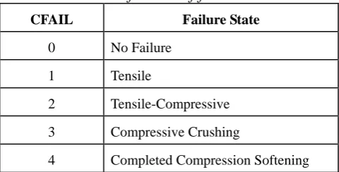
The strain εt at which the stress reduces to zero in tension and the strain εc at which the stress reduces to zero in compression are used in this analysis. The value εt is 0.000768 (4 times the tensile failure strain) and the value εc is 0.0141 (3 time the compressive failure strain). The definition of the concrete failure states are presented in the Table 1.
Fig. 1. Definition of CFAILs on failure surface of the failure surface (a) and on uniaxial
stress-strain curve for concrete (b)
Table 1. Definition of failure states
CFAIL Failure State
0 No Failure
1 Tensile
2 Tensile-Compressive 3 Compressive Crushing
4 Completed Compression Softening
NEPTUNE calculates stresses at the centroid of the concrete element at five integration points through the thickness and in each rebar layer. In the model, layers of individual reinforcing bars of the concrete walls are represented by smeared uniformly distributed layers of steel. The thickness of these layers is determined by assuming that the cross-sectional areas of the reinforcing bars are spread uniformly along the respective pitch of the layers. The direction of reinforcement is specified in the sandwich element model. Transverse wall reinforcement and liner are neglected in the analytical model.
Some composite metal frames, made from different steel components, are imbedded in the walls. These structures were modeled using separate beam finite elements and were added to walls and slabs in the locations of the frames. The beam transmits moments, torque and forces and is a general six (6) degree of freedom element (i.e., three global translation and rotational components at each end of the member) (Belytschko, 1977). The 3-D beam element is a three-dimensional uniform cross-section element capable of performing large deformations and elasto-plastic analysis of general beam-frame problems. The cross-section change of shape is not accounted for in any analysis.
2.2 Boundary conditions of models
large. For simplicity, therefore, the locations of the external nodes, which would be in fact connected to adjacent structures, are assumed to be completely fixed in translation.
2.3 Description of finite element model
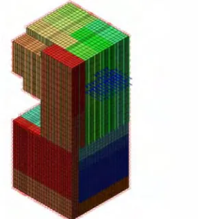
The finite element model of the Ignalina NPP building part is presented in Fig. 2. One crash/impact location was considered in this paper. Arrows depict the assumed impact area of the airplane. The impact direction is assumed to be perpendicular to the selected wall of the building.
The model developed with the ALGOR software was converted to NEPTUNE input format, and NEPTUNE performed the transient structural analysis.
The walls and slabs of the compartments of the NPP building are made of reinforced concrete. Reinforced concrete walls and slabs were modeled using four-node quadrilateral plate elements. In some walls metal frames made from different steel components were imbedded. These structures were modeled using separate beam elements and were added to walls and slabs at the locations of the frames. The geometrical data for the compartments of the Ignalina NPP building were obtained from drawings.
Fig. 2. The model for finite element analysis of the Ignalina NPP building
The impacted wall of the building, a portion of which is shown in Fig. 3, has 25 mm diameter reinforcement bars with a pitch of 250 mm, 12 mm diameter bars with a pitch of 125 mm and 600 mm and steel columns (Fig. 3b). The rebar layers A and B are combined as rebar layer 1 in the input file. The rebar layers C and D are combined as rebar layer 2 in the input file.
a) b)
Fig. 3. The cross – section of part of the aircraft-impacted wall
In 1998 (Ignalina, 1988) experiments were carried out using concrete and reinforcement bar specimens taken from the Ignalina NPP to determine in site material properties. The measured concrete properties are presented in Table 2. The results are the average of 7 samples. The experimental data for the concrete and the reinforcement bars was used in this analysis.
Table 2. Experimental data of Concrete (Ignalina, 1988)
Material Type (Russia
n brand)
Young’s modulus, MPa
Poisson ’s ratio
Tensile strength (concrete)/ Yield stress (steel), MPa
Compressive strength (concrete)/ Ultimate strength (steel), MPa
Concrete M300 1.95e4 0.184 3.8 51.6 0.47 Steel of
reinforcement
AIII 22.25E4 - 443 697 -
3. LOADS FOR ANALYSIS
The aircraft impact loading, applied to NPP buildings, needs to be determined. Usually, the load/time function used in studies of airplane crashes corresponds to the guidance provided in the IAEA safety guide, which specifies that the load/time-function for a crash of a military aircraft (General Dynamics Phantom RF-43E with a velocity of 215 m/s, whose impact area is assumed to be 7 m2) should be used.
A two engine commercial airliner is one of the most common aircraft used in Lithuania and, thus, is most likely to fly over the Ignalina NPP. The aircraft is a short-to-medium range airplane and is used primarily for continental flights. The impact force loading history for this airplane was determined using a Riera loading function. The impact area includes the frontal areas of the body, the engines and the wings.
4. TRANSIENT ANALYSIS OF AIRPLANE CRASH EVENTS
The crash of a commercial airliner into an Ignalina NPP structure is a transient dynamic problem and is governed by the structural dynamic equations of motion. The semi-discretized equations of motion (Kulak, 1988) are given by:
,
int ext iI iI iI iIu f f
m + = (no sum) (3)
where miI is a diagonal mass matrix and üiI is the nodal displacement of node I in the i-th direction, fiIint and fiIext are the internal and external nodal forces, respectively.
The central difference integrator is used to solve the equations of motions. This integrator is well suited for the treatment of transient (short duration) problems in which the variation of element eigenvalues over the mesh is not large. The acceleration, velocity, and displacement are obtained from central difference formulas:
) , ( / )) ( ) ( ( )
(n f n fintn m n
u iI iI
ext iI
iI = −
,
no sum (4)) ( ) 2 / 1 ( ) 2 / 1
(n u n tu n
uiI + =iI − +Δ iI (5)
) 2 / 1 ( ) ( ) 1
(n+ =u n +Δtu n+
uiI iI iI
,
(6)where Δt is the time increment and n is the step number.
The effect of strain-rate for concrete, rebars and steel are important for the material response under dynamic impact loading. Therefore a new strain-rate-dependent version of NEPTUNE was developed at ANL. The strain-rate effect on the dynamic flow stress for steel (quadrilateral plate and beam elements) was programmed using the Cowper-Symonds equation:
q static
dyn D
/ 1
)) / ( 1 ( ε
σ
σ = +
,
(7)where σdyn is the dynamic flow stress, σstatic is the static flow stress,
ε
is the strain-rate, q is the steel strain-rate amplitude parameter and D is the reference strain-rate.The strain-rate effect of the rebars and of the compressive and tensile concrete strength was programmed using dynamic increase factors (DIF) described by Malvar and Crawford (Malvar, 1998 and Crawford, 1998). It was assumed that the DIF data can be approximated by a straight line in a logarithm of the DIF versus logarithm of strain-rate plot. The adopted DIF formulation was, for both yield and ultimate stress:
α ε/10 ) ( −4
=
DIF
,
(8)where for the yield stress, α=αfy was found to be: 60
/ 040 . 0 074 .
0 y
fy= − f
α
,
(9)and for the ultimate stress, α =αfy was found to be:
y fy=0.019−0.009f
α
,
(10)The strain-rate
ε
is in s-1 and fy is the rebar yield strength. The rebar reference static yield stress value of 414 MPa was used for the analysis.1 3 / 1 1 026 . 1 30 , ) / ( 30 , ) / ( / − − > = ≤ = s for y s for f f s s s s cs c ε ε ε ε ε ε α
,
(11)where fc – dynamic compressive strength at
ε
, fcs – static compressive strength atε
s, fc/fcs – compressive strength dynamic increase factor,ε
- strain-rate in the range of 30x10-6 to 300 s-1,ε
s- 30x10-6 (static strain-rate), log γ =6.156α - 2, αc=1/(5+9fcs/fco), fco = 10 MPa.This DIF formulation for concrete in compression has typically been accepted by most researchers as an accurate representation of actual behavior, and is used here for direct application in numerical analysis.
The dynamic increase factor for the tensile strength is given by (Crawford, 1998):
1 3 / 1 1 1 , ) / ( 1 , ) / ( / − − > = ≤ = s for s for f f s s ts t ε ε ε β ε ε ε δ
,
(12)where ft – dynamic tensile strength at
ε
, fts– static tensile strength atε
s, ft/fts – tensile strength dynamic increase factor,ε
- strain-rate in the range of 1x10⁻⁶ to 160 s-1,ε
s- 10-6 (static strain-rate), log β =6δ - 2, αc=1/(1+8fcs/fco), fco = 10 MPa. (The compression static strain-rate value of 3 x 10⁻⁵ s-1 and the tensile static strain-rate value of 1 x 10⁻⁶ s-1 were used for the analysis.)Concrete failure flags have been incorporated into the NEPTUNE code to determine when failure occurs and what type of failure occurred. The code determines which layers of concrete are subjected to tension and which are subjected to compression and performs calculations up to the tension and compression limits. The code outputs the following concrete failure flags (Table 1) which describes how the element failed:
0 No failure
1 Tensile failure surface (see Fig. 1) reached – limit for tension is reached, the concrete cracking begins, and is tensile failure only;
2 Tensile and compressive failure surface (see Fig. 1, a) is reached – tension evaluation is completed and the crack in concrete starts to open;
3 Compressive failure surface (see Fig. 1) is reached – element reaches ultimate strength in compression, and is compressive failure only;
4 The compressive failure strain (ec, see Fig. 1, b) is reached – element reaches compressive failure strain, and looses resistance to any loading.
The code prints the following message about rebar failure: “Rebar failure – element reaches ultimate strength and looses resistance to any loading.”
The results from the transient analysis of the Ignalina NPP building at the time step of maximum loading (0.185 s) are depicted in Fig. 4, a. The numbers of the elements and nodes of the FE model for which results are presented here are shown in Fig. 4, b The displacement distribution in the outside and inside walls of the building is shown in Fig. 4, a. The maximum displacement was located in the airplane-impacted wall with a value of 0.00422 m. The temporal evolution of element stresses and nodal displacements and velocities are depicted in Fig. 5 through Fig. 7. The temporal variation of the velocity and displacement of impacted wall node (number 8362 is located in the impacted area) are presented in Fig. 5, a. The maximum displacement is 4.64 mm and the maximum velocity is 1.01 m/s at this node.
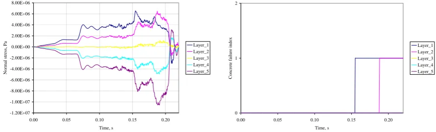
The temporal variation of the normal and shear stresses in the concrete element (number 7435 is located in the impacted area) at layer 1 of impacted wall are presented in Fig. 5, b. The results show that the normal stress σxx is the largest with a value of 6.56 MPa. The other stresses are smaller. The maximum strain is 4.17 x 10⁻⁴ . The ultimate strain limit (4.70 x 10⁻³, experimental data) was not exceeded.
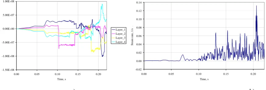
The temporal variations of the axial stresses in the rebars of element 7435 at all three layers are presented in Fig. 7, a. Results show that the stress is the largest with a value of 102 MPa in layer 1. No information about rebar failure in the NEPTUNE output file was indicated. The static ultimate strength for rebar steel is 850 MPa (experimental data). The temporal variations of the strain-rate in the reinforcement bar (element 7435) at layer 1 of impacted wall are presented in Fig. 7, b. The results show that the largest strain-rate is 0.132 s-1 at the peak of axial stress, i.e., at the time of 0.206 s.
The information about ‘tensile and compressive failure is reached’, ‘compressive failure surface is reached’ and ‘rebar failure’ in the NEPTUNE output file was not observed. This means that the structural integrity of Ignalina NPP building will not be destroyed under the conditions assumed in this analysis.
a) b)
Fig.4. The displacement (m) of the building walls (a) and the numbers of elements and nodes of
the model
-0.40 -0.20 0.00 0.20 0.40 0.60 0.80 1.00 1.20
0.00 0.05 0.10 0.15 0.20 Time, s
V
elocity, m/s
-5.00E-03 -4.00E-03 -3.00E-03 -2.00E-03 -1.00E-03 0.00E+00 1.00E-03 2.00E-03
D
is
p
lacement, m
Velocity, m/s Displacement, m
-4.00E+06 -2.00E+06 0.00E+00 2.00E+06 4.00E+06 6.00E+06 8.00E+06
0.00 0.05 0.10 0.15 0.20
Time, s
St
re
ss,
Pa Normal stress_xx
Normal stress_yy Shear stress_xy
a) b)
Fig.5. The displacement and velocity time history of node 8382 located in the impacted area (a)
and the normal and shear stress time history in the concrete element 7435 of the
impacted wall (b)
-1.20E+07 -1.00E+07 -8.00E+06 -6.00E+06 -4.00E+06 -2.00E+06 0.00E+00 2.00E+06 4.00E+06 6.00E+06 8.00E+06
0.00 0.05 0.10 0.15 0.20
Time, s
Nor
m
a
l str
e
ss, P
a
Layer_1 Layer_2 Layer_3 Layer_4 Layer_5
0 1 2
0.00 0.05 0.10 0.15 0.20
Time, s
C
onc
re
te
fa
il
u
re
i
nde
x
Fig.6. The normal stress time history in the concrete element 7435 of the impacted wall (a) and
the concrete failure index of the impacted wall element 7435 (b)
-1.50E+08 -1.00E+08 -5.00E+07 0.00E+00 5.00E+07 1.00E+08
0.00 0.05 0.10 0.15 0.20
Time, s
Axia
l str
ess, P
a
Layer_1 Layer_2 Layer_3 Layer_4
-0.02 0.00 0.02 0.04 0.06 0.08 0.10 0.12 0.14
0.00 0.05 0.10 0.15 0.20
Time, s
St
rai
n
rat
e, 1
/s
.
a) b)
Fig. 7. The axial stress time history in the reinforcement bars in element 7435 of the impacted
wall (a) and the strain-rate time history in the reinforcement bars in element 7435 of the
impacted wall
5. LOCAL RESPONSE EVALUATION
In addition to evaluating the global structural response of the Ignalina NPP building to aircraft impact, it is necessary to evaluate the local response due to impact from semi-hard missiles, such as the aircraft engine. Since the local response of the reinforced concrete wall from missile impact is very difficult to model analytically, the accepted approach is to use empirical formulas that have been derived from physical tests of missiles impacting against concrete structures. The U.S. Department of Energy ACRAM Standard (DOE, 1995) recommends the Chang formulas for evaluating perforation and scabbing phenomena of aircraft crash into concrete structures.
The Chang formula for minimum wall thickness, ts, to prevent scabbing resulting from impact by a hard missile is given by:
] ) ( / ) [( ) / ( 84 .
1 0.13 0.4 0.2 ' 0.4 c
s U V M V D f
t = × × × (13)
where U is the reference velocity (200 ft/sec; 61 m/sec), V is the velocity of the engine (ft/sec), M is the mass of the missile (lbf-sec2/ft), D is the equivalent diameter of the engine (ft) and f’c is the compressive strength of concrete. The DOE Standard recommends reducing the value of ts by a factor of 0.6 to account for the fact that the missile (engine) is deformable. The Standard then requires that the minimum design thickness, tsd, to prevent scabbing be scaled up by a factor of 1.1 so that the minimum design thickness to prevent scabbing is given by:
s
sd t
t =1.1×0.6× (14)
The Chang formula for minimum wall thickness, tp, to prevent perforation of a hard missile is given by:
)] /( ) [( ) /
( 0.25 2 '
c
p U V M V D f
t = × × (15)
Similar to the scabbing formula, the USDOE Standard applies a reduction factor of 0.7 and a design factor of 1.2 to the calculated penetration thickness of a hard missile; thus, the minimum design thickness to prevent perforation is given by:
p
pd t
t =1.2×0.7× (16)
The power plants for the commercial aircraft are two wing-mounted turbofan engines. Using the parameters for a commercial aircraft the minimum design thickness to prevent scabbing was computed to be 0.756 m (2.48 ft) and the minimum design thickness to prevent perforation was 0.457 m (1.5 ft). The impacted wall is 1 m thick, and, thus no scabbing should occur and the engine should not penetrate the wall.
5. SUMMARY
The transient analysis of a commercial aircraft crashing into an Ignalina NPP building structure was carried out using the NEPTUNE computer code. The purpose of the investigation was to determine if global structural failure of the building could occur. Local failure mechanisms, such as perforation and scabbing, were also considered.
includes the frontal areas of the body, the engines and the wings of the airplane. Strain-rate dependent material models for the concrete and reinforcing bars were used. Also, the values for the material properties used in the models had been obtained from tests on specimens taken from the Ignalina NPP building walls. It is noted that these test values were found to be higher than the standard material properties listed in handbooks (e.g., norms). For an airplane crash, the highest damaged area of the building was the area adjacent to center point of the airplane-impacted area. It was observed that the tensile failure surface was reached in two layers of the impacted wall. This means, that the limit for tension is reached and concrete cracking begins. It is tensile failure only. The compressive failure surface is not reached in any of the layers of the concrete walls. No indication of concrete failure in compression was observed in the NEPTUNE output file. The maximum axial stress in the reinforcement bars element was 150 MPa. The static ultimate strength for rebar steel is 850 MPa (experimental data). It should be noted that the interior walls, which are perpendicular to the impacted exterior wall, provided additional support to the exterior wall.
The results from local response analyses show that the 1.0 m reinforced concrete walls are of sufficient thickness to prevent either scabbing from the backside of the impacted wall or perforation of the aircraft engine through the wall.
According to the results from the crash analysis of a commercial aircraft, it is possible to conclude that the impacted reinforced concrete wall of the Ignalina NPP building will experience cracking of concrete, i.e. the tension strength was exceeded, but the dynamic ultimate strength in compression was not reached. The reinforcement bars of the impacted wall will not fail. Therefore, the structural integrity of the impacted wall of the Ignalina NPP building will be maintained during impact of a two-engine commercial jetliner.
ACKNOWLEDGMENTS
The authors want to extend thanks to the administration and technical staff at the Ignalina NPP, for providing information regarding operational procedures and operational data.
REFERENCES
IAEA Safety Standards Series. External Human Induced Events in Site Evaluation for Nuclear Power Plants. Safety Guide No.NS-G-3.1, 2002.
J.D. Riera, (1968), Jrnl. of Nuclear Engineering and Design, Vol. 8, pp. 415-426.
Kulak R.F. and Fiala C., (1988), Jrnl. of Nuclear Engineering and Design, Vol. 106, pp. 47-68. Algor Finite Element Analysis System, ALGOR Instruction Manuals. Algor, Inc. Pittsburgh, 2000.
Belytschko T., Lin J.I., and Tsay C.S., 1984, Jrnl. of Computer Methods in Applied Mechanics and Engineering, Vol. 42, pp. 225-251
R.F. Kulak and P.F. Pfeiffer, E.J. Plaskacz, (1997), Jrnl. of Nuclear Engineering and Design, Vol. 174, pp. 143-156.
S.S. Hsieh, E.C. Ting and W.F. Chen, (1979), Proc. 3d Eng. Mech. Div. Spec. Conf. ASCE, pp. 437-440. T. Belytschko, L. Schwer and M.J. Klien, (1977), Jrnl. of Intl. J. Num. Meth. In Engrg., No. 11, pp. 64-84. Ignalina NPP ALS Safety Case Report. Volume 3, Lithuanian Energy Institute, 1998 (in Russian).
L. J. Malvar and J. E. Crawford, (1998), “Dynamic Increase Factors for Steel Reinforcing Bars”, 28th DDESB Seminar, Orlando, FL, USA.
J. E. Crawford and L. J. Malvar, (1998), “Dynamic Increase Factors for Concrete”, 28th DDESB Seminar, Orlando, FL, USA.