Copyright to IJIRSET www.ijirset.com 13604
Effect of Damping on Comfort Level of a Fully
Independent Suspension System of An
Automobile
A. Bala Raju1 , R.J. Shruti2, R. Venkatachalam3 1
Research Scholar, Department of Mechanical Engineering, National Institute of Technology, Warangal, India 2
Research Engineer, Department of Applied Mechanics, Cummins Research and Technology, Pune, India 3
Professor, Department of Mechanical Engineering, National Institute of Technology, Warangal, India
ABSTRACT: Suspension system is one of the most important systems of an automobile. One important function of the
suspension system is to absorb the shocks caused by unevenness of the road. One of the present trends of an automobile is fully independent suspension system. The stiffness and damping of the suspension system play an important role in absorbing the shocks and there by provide comfort to the passengers. In this paper, an attempt is made to study the effect of damping on the comfort level. A damping of 1000 N.s./m is found to provide maximum comfort level always.
KEYWORDS: Fully independent suspension systems, Effect of damping, Comfort level
I. INTRODUCTION
The suspension system is one of the most important systems of an automobile. Its main purpose is not only to support the engine, its components, passengers, but also to isolate them from shocks arising due to roughness of the road. It has been a practice from the beginning to have a frame called chassis which is being supported through springs and dampers by the front and rear axles. This type of suspension system is called Conventional Suspension System. There is yet another type of suspension called Independent Suspension. In this type of suspension system, the body of the vehicle itself acts as the chassis. The axle of a wheel is hinged to the body and is held in position by springs and dampers which are placed in between axle and the body. The current trend in the automobile industry is to go for independent suspension system to all the four wheels. Such a suspension system is called fully independent suspension system.
The study of suspension systems has been a subject of interest for many researchers. Studies have been performed using simple models called quarter car model and half car model. These models are simple and yield quick results. However, they are not accurate because they cannot take into account all the possible motions of the body of the automobile.
Some of the early studies performed using quarter car model are due to Hedrick [1], Majjad [2] , Gobbi and Mastin [3]. Among the latest studies, Wei Gao et al. [5] studied dynamic behaviour of passively suspended vehicles running on rough roads. The road profile is considered to give random inputs to the suspension system. Considering nonlinear damping characteristics, Rajalingam and Rakheja [4] studied the dynamic behaviour of quarter car model. Wei Gao et al. [6] also studied the dynamic characteristics considering the mass, damping and tyre stiffness as random variables. Kamalakannan et al. [7] tried adaptive control by varying damping properties according to the road conditions. Thite [8] refined the quarter car model to include the effect of series stiffness. Wei Gao et al. [9] investigated dynamic response of cars due to road roughness treating it as random excitation.
Husiyno Akcay[10], Li-Xing Gao[11], Thite et al.[12], Roberto Barbosa[13] are among those who performed the studies using half car model.
ISSN: 2319-8753
I
nternational
J
ournal of
I
nnovative
R
esearch in
S
cience,
E
ngineering and
T
echnology
(An ISO 3297: 2007 Certified Organization)
Vol. 3, Issue 6, June 2014
Copyright to IJIRSET www.ijirset.com 13605
attempted to maximize the comfort level. Genetic algorithms have been employed to perform optimization to arrive at optimum values of suspension parameters. Hajkurami et al.[17] studied the frequency response of a full car model as a system of seven degrees of freedom. Balaraju and Venkatachalam analysed the dynamic behaviour of an automobile using full car model for both, fully conventional suspension systems[18] and fully independent suspension systems[19]. Aniruth et al.[20] analysed for optimum suspension parameters of semi independently suspended automobiles.
In this paper, an attempt is made to study the effect of the damping on the comfort level offered by a fully independent suspension system of an automobile.
II. FORMULATION
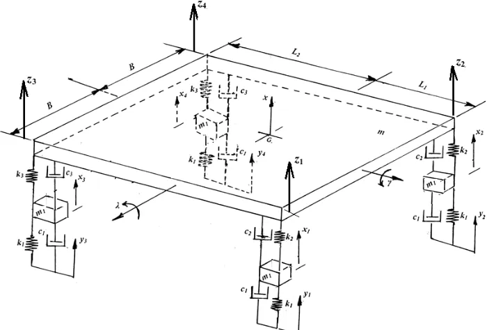
Figure 1 shows the arrangement of a fully independent suspension system. The mass m of the main body, is supported at its four corners. The front side suspension system characteristics are specified by the spring constant k2 and the
damping constant c2. The rear side suspension system characteristics are denoted by the spring constant k3 and the
damping constant c3. The mass m1 indicates mass of the tires. The tire characteristics are indicated by the spring
constant k1 and the damping constant c1. The up and down motions of the tyres may be represented by the variables xi , i = 1 to 4. The up and down motions of the main mass may be indicated by the variable x. The roll and pitch motions may be described by γ and λ. In total the entire system to describe by seven coordinates. The vertical displacements caused by the road roughness may be represented by the variables yi , i = 1 to 4, as shown in the Figure 1. Figure also
shows the absolute linear displacements of the four corners of the main body through the variables zi , i = 1 to 4.
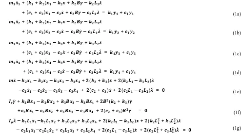
Denoting the mass moments of inertia of the main body about roll and pitch axes, respectively, by and , the equations of motions may be derived as
̈ + ( + ) − + −
+ ( + ) ̇ − ̇+ ̇ − ̇ = + ̇ (1a)
̈ + ( + ) − − −
+ ( + ) ̇ − ̇ − ̇ − ̇ = + ̇ (1b)
̈ + ( + ) − + +
+ ( + ) ̇ − ̇ + ̇ + ̇ = + ̇ (1c)
̈ + ( + ) − − +
+ ( + ) ̇ − ̇ − ̇ + ̇ = + ̇ (1d)
̈ − − − − + ( + ) + ( − )
− ̇ − ̇ − ̇ − ̇ + ( + ) ̇ + ( − ) ̇ = (1e)
̈ + − + − + ( + )
+ ̇ − ̇ + ̇ − ̇ + ( + ) ̇ = (1f)
̈ − − + + + ( − ) + ( + )
− ̇ − ̇ + ̇ + ̇ + ( − ) ̇ + ( + ) ̇ = (1g)
Copyright to IJIRSET www.ijirset.com 13606
Figure 1 Schematic arrangement of full car model of fully independent suspension system
III. ANALYSIS OF THE SUSPENSION SYSTEM
In order to study the comfort level of the passengers, a quantity z2 defined as the sum of the squares of vertical displacements at each corner of the vehicle, is considered. It may be expressed mathematically as
= (2)
where, the displacements zi , i = 1 to 4 may be expressed as
= − +
(3a)
= + + (3b)
= − − (3c)
= + − (3d)
As it is defined, z2is a positive definite quantity, and hence the minimum value is zero. This can happen only when zi , i = 1 to 4 are all zeroes, which implies that all the four corners of the main body are having zero absolute displacements, implying that the main body is not moving at all. Therefore, the best comfort may be achieved when the value of z2 is zero. However, this is an ideal situation. Therefore, one attempts to look for achieving a possible minimum value of z2 .
Based on a practical road vehicle SantroXing, numerical values are assigned to various parameters involved for the semi independent suspension system as follows.
m1 = 40 kg m =1000 kg
ISSN: 2319-8753
I
nternational
J
ournal of
I
nnovative
R
esearch in
S
cience,
E
ngineering and
T
echnology
(An ISO 3297: 2007 Certified Organization)
Vol. 3, Issue 6, June 2014
Copyright to IJIRSET www.ijirset.com 13607
k1 = 2×10⁵N/m k2 = 0.5×10⁵N/m k3 = 0.5×10⁵N/m
c1 = 1000 N.s/m L1 = 1.0 m L2 = 2.5 m B = 0.75 m
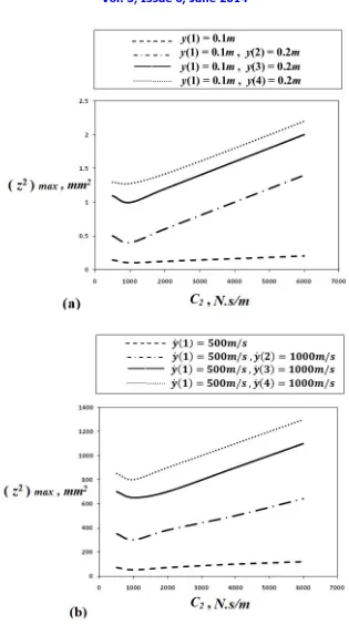
In the present analysis the damping parameters c2 and c3 are taken same as, c2= c3 = c. Some typical disturbances are
chosen as listed in Table 1. The equations of motion expressed in Equation (1) are integrated for each of the disturbance chosen, for different values of c in the range500 to 6000 N.s/m. For each value of c, the maximum value of z2 is noted. Figure 2a shows the variation of ( z2 )max with c, for the cases 1,2,3 and 4 of the Set 1 described in
Table1. Similarly, Figure 2b shows the variation of (z2)max with c for the cases 5,6,7 and 8 of the Set 2. These two
Figures reveal that for a value of c = 1000 N.s/m, the values of ( z2 )max are minimum. Therefore, c2= c3= 1000 N.s/m
may be considered as optimum damping.
Table 1 Different disturbances chosen
Set 1: Displacement disturbances (all are in m).
Case 1 (0) = 0.1 (0) = 0 (0) = 0 (0) = 0
Case 2 (0) = 0.1 (0) = 0.2 (0) = 0 (0) = 0
Case 3 (0) = 0.1 (0) = 0 (0) = 0.2 (0) = 0
Case 4 (0) = 0.1 (0) = 0 (0) = 0 (0) = 0.2
Set 2: Velocities disturbances (all are in m/s).
Case 5 ̇ (0) = 500 ̇ (0) = 0 ̇ (0) = 0 ̇ (0) = 0
Case 6 ̇ (0) = 500 ̇ (0) = 1000 ̇ (0) = 0 ̇ (0) = 0 Case 7 ̇ (0) = 500 ̇ (0) = 0 ̇ (0) = 1000 ̇ (0) = 0 Case 8 ̇ (0) = 500 ̇ (0) = 0 ̇ (0) = 0 ̇ (0) = 1000
The existence of optimum value of damping may be explained as follows. When damping is nearly zero, the system would be an undamped system. Therefore, one can expect large amplitudes of forced vibrations. When damping is very large, it may be realised that the damper is providing a rigid connection of the main body to the axles. Hence, the entire disturbance is directly transferred to the main body. One should allow free movement of the plunger of the damper for pumping out the energy of the system effectively. Therefore, there must exist an optimum value of damping.
IV. CONCLUDING REMARKS
The work presented in this paper and significant conclusions that may be drawn based on the present work may be summarized as follows.
(i) A full car model of fully independent suspension system is studied for optimum damping parameters. (ii) For the purpose of study, the values of various other parameters are taken which correspond to a real
practical automobile.
(iii) A quantity z2 is defined to indicate the comfort level for the passengers.
(iv) The damping of the shock absorber is varied from 500 to 6000 N.s/m in steps of 500 N.s/m. For each damping value the time response is observed for some typical disturbances and the maximum value of
z2 is noted.
(v) The reason for the existence of an optimum value of damping is discussed.
Copyright to IJIRSET www.ijirset.com 13608
ISSN: 2319-8753
I
nternational
J
ournal of
I
nnovative
R
esearch in
S
cience,
E
ngineering and
T
echnology
(An ISO 3297: 2007 Certified Organization)
Vol. 3, Issue 6, June 2014
Copyright to IJIRSET www.ijirset.com 13609 REFERENCES
[1] Hedrick, J. K., Nonlinear control of a Quarter Car active suspension, Proceedings of the American Control Conference, Chicago, June 1992.
[2] Majjad, R., Estimation of suspension parameters, Proceedings of the IEEE International Conference on Control Application, Hartford, October 1997.
[3] Gobbi, M. and Mastinu, G., Analytical description and optimization of the dynamic behaviour of passively suspended road vehicles, Journal of Sound and Vibration, Vol. 245, No.3, pp. 457 – 481, 2001.
[4] Rajalingam, C. and Rakheja, S., Influence of suspension damper asymmetry on vehicle vibration response to ground excitation, Journal of Sound and Vibration, Vol. 266, pp.1117 – 1129, 2003.
[5] Wei Gao, Nong Zhang, Dynamic analysis of vehicles with uncertain parameter, 14th International Congress on Sound and Vibration,
Australia, July 2007.
[6] Wei Gao, Nong Zhang, and Jun Dai, A stochastic quarter car model for dynamic analysis of vehicle with uncertain parameters, International Journal of Vehicle Mechanics and Mobility, Vol. 46, No.12, pp. 1159 – 1169, 2008.
[7] Kamalakannan, K., Elaya Perumal, A., Mangalaramanan, S., Arunachalam, K., Performance analysis of behaviour characteristics of CVD (semi active) in quarter car model, Jordan Journal of Mechanical and industrial engineering, Vol. 5, pp. 261 – 265, June 2011.
[8] Thite, A.N., Development of a refined quarter car model for the analysis of discomfort due to vibration, Advances in Acoustics and Vibration, Hindawi Publishing Corporation, 2012.
[9] Wei Gao, Zhang, N., and Du, H.P., A half-car model for dynamic analysis of vehicles with random parameters, 5th Australasian Congress on Applied Mechanics, Brisbane, Australia, December 2007.
[10] Husenyin Akcay, and Semiha Turkay, Influence of tire on mixed H2 / H∞ synthesis of half car active suspensions, Journal of Sound and
Vibration, Vol. 322, pp.15 – 28, 2009.
[11] Li-Xing Gao, and Li-Ping-Zing., Vehicle vibration analysis in changed speeds solved by pseudoexcitation method, Mathematical Problems in Engineering, Hindawi Publishing Corporation, 2010.
[12] Thite, A.N., Banvidi, S., Ibicek, T., and Bennett, L., Suspension parameter estimation in the frequency domain using a matrix inversion approach, International Journal of Vehicle Mechanics and Mobility, Vol. 49, No.12, pp. 1803 – 1822, 2011.
[13] Roberto Spinola Barbosa, Vehicle dynamic response due to pavement irregularity, Journal of Brazilian Society of Mechanical Sciences and Engineering, Vol. 33, No. 23, pp. 302 – 307, 2011.
[14] Libin Li, and Qiang Li., Vibration analysis based on full multi-body model for the commercial vehicle suspension system, Proceedings of the 6th International Conference on Signal Processing, Robotics and Automation, Greece, pp. 203 – 207, February 2007
[15] Pater Gaspar and Laszlo Nadai., Estimation of dynamical parameters of road vehicles on freeways, 5th International Symposium on
Intelligent Systems and Informatics, Serbia, August 2007.
[16] Anil Shirahatt, Prasad, P.S.S., Pravin Panzade, and Kulkarni, M.M., Optimal design of passenger car suspension for ride and road holding, Journal of Brazilian Society of Mechanical Sciences and Engineering, Vol. 30, No.1, pp.66 – 74, 2008.
[17] Hajkurami, H., Samandari, H., Ziaei-Rad, S., Analysis of chaotic vibration of nonlinear seven degree of freedom full car model, 3rd
International Conference on Integrity, Reliability and Failure, Portugal, July 2009.
[18] Balaraju, A. and Venkatachalam, R., Analysis of vibrations of automobile suspension system using full car model, International Journal of Scientific and Engineering Research, Vol. 4, Issue 9, pp. 2305-2311, September 2013.
[19] Balaraju, A. and Venkatachalam, R., A study on conventional versus independent suspension system of an automobile, Applied Mechanics and Materials, Vols. 541-542 pp. 827-831, 2014.