Seismic Evaluation of Existing Nuclear Facility Using Non Linear
Modelling
D.Combescure, P.Sollogoub, E.Jeanvoine, I.Politopoulos (1)
1) Seismic Mechanic Study Laboratory, DEN/DM2S/SEMT, CEA Saclay, 91191 Gif/Yvette Cedex, France
ABSTRACT
This paper aims at presenting the methodology and the non-linear modelling used for the seismic evaluation of existing nuclear facilities. Two different calculation methods are applied to the seismic analysis of a 4 storey reinforced concrete frame tested with the pseudynamic method. In a first step, static and dynamic analysis are conducted with non linear beam elements. The second part shows the application of the simplified hinge method based on a event-to-event dynamic calculation. The main problems to be solved during the seismic assessment of existing facilities regarding the utilization of non linear modeling such as the definition of damage index according safety requirements are discussed in this paper.
INTRODUCTION
In the oldest industrial countries specially with moderate seismicity such as France, the main part of the building stock has been designed before the application of the modern seismic code. Because of the absence of any seismic consideration at the period of the construction or the modification of the action levels, many structures do not satisfy the actual requirements. Due to safety reasons, the case of nuclear facilities and plants may be critical and requires detailed seismic evaluations. The application of simplified procedures used for design -elastic computation and reduction by a q-factor- tends to give unrealistic results and, overall, masks the critical points for the facility safety.
This paper aims at presenting the methodology and the non-linear modelling used for the seismic evaluation of existing nuclear facilities.
Two types of modelling methodology are described and compared in the case of a R/C frame.
- On one hand, time history non linear computations are performed using non linear global constitutive laws representing the behaviour of each structural elements. For the RC beam and column elements, a fibre type model based on beam elements and uniaxial material laws can be used. Non structural elements such as masonry infill panel and RC squat shear walls can also be considered by mean of diagonal strut and shear beam models.
- On another hand, a simplified hinge method already used for piping system has been applied to the study of the R/C frame.
These two methodologies have been applied to the analysis of a 4 storey reinforced concrete frame tested in ELSA Laboratory in JRC Ispra with the pseudodynamic testing method. The steel reinforcement of this structure is representative of the buildings of the 1940-70’s.
DESCRIPTION OF THE NON LINEAR MODELLING
Examples of Non Linear Constitutive Laws
The non-linear numerical models are usually divided in two classes :
- the global models reproducing the behaviour of complete structural elements at a reduced cost can be used to study the behaviour of complete structures under complex static and dynamic loading. In this level of modelling, beams and columns are usually replaced by beam elements with concentrated hinges, shear walls by global shear beam model and infill panels by two diagonal trusses supporting only compression forces.
- the local models allow to study structural components knowing only the characteristics of the basic materials but are much more time consuming to use - not only in term of cpu time but also in term of preparation of datas and processing of results -.
These two levels can be used in a complementary way : the local modelling allows used to identify the parameters of the global models and highlight the limitations of these models (for example, what are the limits of the assumption of the 2 diagonal for the infill panels ). Such approach has been applied with Castem2000 finite element code [1] for the analysis of infilled frame [2] and shear wall structures [3].
SMiRT 16, Washington DC, August 2001 Paper # 1323
A Timoshenko Beam Element With Non Linear Shear Behaviour
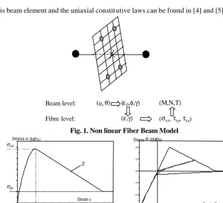
The seismic analysis of complete building structures with dynamic or simplified push-over analysis requires simplified non linear finite elements. The behavior of reinforced concrete members such as columns, beams but also structural walls can be very well reproduced using non linear beam elements with fiber type assumptions at the section level.
This modeling is based on a geometrical description (Fig 1) of the beam section in fibers (or layers in 2D). The axial and shear strains in each fiber are deduced directly from the average axial εx and shear strains γy, γz, the curvatures (in flexion φy, φz and torsion φx) of the beam element and the section geometry.
( )
ε
x i=
ε
x−
y
i⋅
φ
z+
z
i⋅
φ
y (1)( )
γ
y i=
γ
y−
z
i⋅
φ
x and( )
γ
z i=
γ
z+
y
i⋅
φ
x (2)The normal force Nx, bending moments My, Mz, shear forces Ty, Tz and twisting moment Mx are calculated by integrating the axial and shear stresses in the section.
∫
=
Sx
x
dS
N
σ
,=
∫
⋅
S x
y
z
dS
M
σ
and=
−
∫
⋅
S x
z
y
dS
M
σ
(3)∫
=
Sy
y
dS
T
τ
,=
∫
S z
z
dS
T
τ
and=
∫
⋅
−
⋅
S
y z
x
y
z
dS
M
(
τ
τ
)
(4)Each fiber supports a uniaxial law σ(ε) representative of concrete or steel behaviour. Fig 2 and Fig 3 show the laws used in the present study respectively for concrete (with softening in compression and tension) and for steel (with hardening, Bauschinger effect and buckling).
A simple Timo shenko beam element has been adopted in order to allow shear distortion and so the use of non linear constitutive laws not only for bending but also for shear and torsion. In order to avoid shear locking, this 3D beam element has a unique Gauss point and t he axial strain, curvature and shear strain remain constant on the element.
Details of this beam element and the uniaxial constitutive laws can be found in [4] and [5].
Beam level: (u, θ) (ε0,φ,γ) (Μ,Ν,Τ)
Fibre level: (ε,γ) (σxx, τxy, τxz)
Fig. 1. Non linear Fiber Beam Model Stress σ (MPa)
Strain ε
Z σc0
εc0
σpt
-0,0001 0,0000 0,0001 0,0002 0,0003 0,0004 -3
-2 -1 0 1 2 Stress σ ?(MPa)
Strainε
a/ Behaviour in compression b/ Behaviour in traction
Stressσ(MPa)
Strain ε Eh<0
E Er<E
Fig. 3. Menegotto-Pinto uniaxial law with Bauschinger effect and buckling for steel Some remarks on the Influence of the Construction Details on Modelling
The accuracy of the modeling and the prediction of failure depends strongly on the capacity to take into account the construction details specially for the reinforced concrete frame structures.
For example, the concrete law shown Fig 2 although it is uniaxial can be directly influenced by the confinement of the stirrups by modifying the ultimate compressive strength and the softening slope Z. A decrease of softening due to higher confinement ratio improves the curvature ductility capacity. The confinement can also be taken into account by modifying the local failure criteria (let say the concrete ultimate strain).
Another major difficulty in the modeling of frame structures up to flexural failure is the localization phenomena due to softening or limited hardening after yielding of the steel bars. This phenomena makes the local results (curvature and strain demands) strongly dependent on the mesh size and requires to fix the length of the elements –the plastic hinges - where damage may concentrate. This is equivalent to consider plastic rotations or chord rotations as failure criteria.
TIME HISTORY ANALYSIS OF A 4 STOREY REINFORCED CONCRETE FRAME
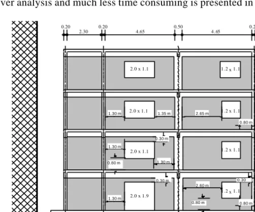
Characteristics of the experimental campaign on the 4 Storey Structure
Two full-scaled reinforced concrete specimens have been tested with the pseudodynamic testing method in JRC Ispra. The 2 specimens have identical concrete frame designed essentially for gravity loads and a nominal load of 8% of its weight but have been tested in several configurations (bare frame, infilled frame before and after reparation and strengthening). Its reinforcement details were specified to be representative of buildings constructed over 4. years ago in European Mediterranean countries such as Italy, Portugal and Greece [8], [9].
The present paper concerns only the bare frame structure without strengthening. This structure has been tested with 2 signals representative of 475 years and 975 years return periods. The second tests have been interrupted in order to limit the damage in the structure and be able to strengthen it. The behavior of the bare frame structure has been mainly dominated by the stiffer column which changes of geometry and reinforcement between the 2nd and the 3rd storey. During the 975 years return period test, damage and interstorey drift concentrated in the 3rd storey (maximum value: 2.41%). Damage was limited to some crushing in the stiff column.
Numerical model of the structure
The non linearities have been assumed concentrated in localized plastic hinges at the extremities of the columns and beams modeled with the non linear fiber type beam element. The length of plastic hinge has been taken equal to the column width for this study. Elastic Bernoulli beam elements with linear curvature have been used for the central part of the columns and beams. A 20000 MPa Young modulus has been considered for the elastic behaviour. Effective width of the slab has been taken equal to 2.00 m, 0.85 m and 0.25 m in the 3 different models used for this study. This assumption can strongly changes the elastic stiffness and ultimate strength of the beams and so the strength of each storey and the global failure mechanism.
For example, the 1st natural frequency depends strongly of the effective width: 1.59 Hz for the model with 2.00 m effective width vs 1.29 Hz for the model with no slab contribution.
A damping matrix proportional to the stiffness matrix has been considered with 2% damping on the 3rd natural frequency (about 7.0Hz). The damping has been reduced in the non linear elements by a factor equal to 10.
Dynamic Analysis
These difference can also be explained by the limitations of the numerical constitutive law since the global strength has also been overestimated.
The results of the dynamic computations have been analyzed by defining a lo cal curvature demand µ and a damage index D function of the ultimate and yielding curvatures:
yielding
φ
φ
µ
max=
andyielding failure yielding
D
φ
φ
φ
−
−
φ
=
max (5) The ultimate curvatures φfailure are given by a preliminary section analysis and correspond to the local failure criteria of 0.35% in compression (for concrete) and 5% in tension (for steel). For the model with no slab contribution, the local damage index was maximum at the 3rd storey for the criteria compression and equal to 0.168, 0.245 and 0.964 respectively for the 475, 975 and 3000 years return period signals.The non linear computations give also the shear demand in all the structural members. Table 2 gives the shear forces and shear stresses in the stiffer column in the 1st and 3rd storeys. The shear demand has been compared to the shear strength computed with the Priestley’s formula [6]. In this formulae, the shear strength is separated in the contributions of steel, of concrete and of the inclined axial force. In the table 2, the contributions of steel and concrete have been given together (the stirrups provide a uniform shear strength of 0.60MPa). The shear demand remains lower than the shear strength calculated for a low ductility demand. This is in accordance with the experimental results and the fact the structure sustains the 475 years return period earthquake without damage.
This application shows the capabilities of the non linear models to reproduce the seismic behavior of a real structure. But the difficulties of such time-history analysis can present difficulties which make increase dramatically their cost for real existing structures (number and choice of the accelerograms for example). A simpler method close to a push over analysis and much less time consuming is presented in the next chapter.
2.20 2.20 2.20 2.20 0.50 0.50 0.50 0.50 4.60 4.60
2.30 0.20 0.60 0.20 0.20 4.65 4.65 2.30 0.20 0.50 0.20 0.20
2.0 x 1.9
1.30 m
0.30 m
1.2x1.1
0.80 m 2.60 m
0.30 m
0.80 m
2.0 x 1.1
0.80 m 1.30 m
0.30 m
2.65 m
1.2x1.1 1.2x1.1 1.2x1.1
2.0 x 1.1 2.0 x 1.1
1.30 m
1.30 m 1.35 m
0.80 m
Fig. 4. Full scale 4 Storey Reinforced Concrete Frame tested at Ispra (configuration with masonry infills)
Table 1. Main numerical results – Bare frame (model with no slab contribution)
475 years numerical 475 years experimental 975 years numerical 975 years experimental (1)
3000 years Numerical
Max. acceleration 2.18 m/s2 2.18 m/s2 2.88 m/s2 2.88 m/s2 4.27 m/s2
Top displacement 71.5 mm 60.8 mm 77.8 mm(2) 116.7 mm 167.4 mm
Base shear 219 kN 209 kN 272 kN(2) 217 kN 304 kN
Drift at 4th storey 0.58% 0.46% 0.70%(2) 0.91% 1.47%
Drift at 3rd storey 0.76% 0.79% 0.91%(2) 2.41% 2.25%
Drift at 2nd storey 0.81% 0.73% 0.96%(2) 1.03% 1.76%
Drift at 1st storey 0.63% 0.44% 0.85%(2) 0.63% 1.86%
(1)
The test was interrupted after 7.0s (2)Max. values are reached before 7.0s
475 years 975 years 3000 years Shear strength (high ductility)
Shear strength (low ductility) 3rd storey
Shear forces Shear stress 108.1 kN 0.865 MPa 118.1 kN 0.945 MPa 126.0 kN 1.01 MPa (217.+53.7) kN (1.74+0.43) MPa (100+53.7) kN (0.80+0.43) MPa
1st storey Shear forces Shear stress 202.1 kN 1.35 MPa 184.9 kN 1.23 MPa 218.3 kN 1.46 MPa (261+157) kN (1.74+1.05) MPa (120+157) kN (0.80+1.05) MPa
0 2 4 6 8 10 12 14 16 18 20 -300 -200 -100 0 100 200 300 Numerical Experimental
Shear force (kN)
Time (s)
0 2 4 6 8 10 12 14 16 18 20 -80 -60 -40 -20 0 20 40 60 80 Time (s) Top displacement (mm)
Numerical Experimental
475 years signal
0 1 2 3 4 5 6 7 8
-125 -100 -75 -50 -25 0 25 50 75 100 125
Top displacement (mm)
Time (s)
Numerical Experimental
975 years signal
Fig. 6. Top displacement and base shear force - Model with no slab contribution
APPLICATION OF THE SIMPLIFIED HINGE METHOD
Description of the Hinge Method
The hinge method is an incremental event-to-event computational method. At each event, the rotational constraint corresponding to the yielded plastic hinges becomes free. This is equivalent to consider an elastic perfectly plastic constitutive law for the plastic hinges. Between two events, the « intermediate » structure is assumed to behave elastically and a classical modal analysis is performed.
It is assumed that the state of the structure (displacements, plastic rotations at the beam and columns extremities, internal forces) are the sum of the results given by the elastic computations at all the previous steps:
∑
=
step step elasticd
d
, , θp θp stepstep
=
∑
, and=
∑
step
step elastic
F
F
, (6)Furthermore, the ground acceleration is the sum of the ground accelerations at all the previous steps: a astep
step
=
∑
(7)spectral acceleration of the elastic spectra at the 1st natural frequency of the structure. This choice has been done because the hinge method uses a tangent stiffness and not a secant one to compute t he natural frequency. This approximation can conduct to unrealistic low frequency.
Once the number of free hinges has reached the degree of hyperstaticity, a failure mechanism appears: the structure can not support anymore an horizontal static loading and has a null natural frequency. The corresponding global displacement is noted dmechanism. Under dynamic loading, this does not mean the structure fails but only that the internal forces can not increase anymore. The failure of the structure is reached only when the plastic rotation at the beams and columns extremities becomes higher than the failure rotation. The failure displacement is noted dfailure.
The computation begins by an elastic computation with the target response spectra which is reduced by a factor allowing to reach exactly the yielding of the first plastic hinge. At each step, the same procedure is used except after the creation of the mechanism. For this last step, the computation is controlled in term of displacement. The main results are the global curve base shear versus top displacement, the failure mechanism and the ground acceleration corresponding to the creation of the mechanism amechanism. Under static loading, this acceleration would lead to the structure instability and so failure.
dfailure
dmechanism
delastic
Top displacement Base shear force
Tmax
Kini
Fig. 7. Base shear versus top displacement
The global curve allows to compute the global ductility µ , the reference elastic displacement delastic being
d T
K
elastic ini
= max , Kini the initial stiffness.
Since a structure resis ts under seismic loading by mean of strength and also ductility, the ground acceleration corresponding to the structure failure is equal to :
mechanism
failure
a
a
=
µ
⋅
ora
failure=
2
µ
−
1
⋅
a
mechanism (8)This computational method is very closed to a push-over analysis with a seismic loading function of the evolution of deformed shape (adaptative loading). Another important advantage of this method is its robustness since there is no iteration and so no convergence problem.
Simplified calculation of the ultimate bendi ng moments and rotations
Since the hinge method is a simplified method of analysis, it requires simple identification procedures for the ultimate bending moments and the ultimate plastic rotations of the plastic hinges.
We note:
- a,b : Dimensions of the rectangular column section
- ϖ : Geometrical percentage of the steel bars on one face of the section - σn: Axial stress
- fc : Concrete strength
- fy : Yielding stress of the steel bars
The total compressive force in the rectangular concrete block Fc and the force in the steel bars after yielding
Fs can be respectively written as:
c
c
b
a
f
F
=
0
.
8
⋅
α
⋅
⋅
⋅
andF
s=
ϖ
⋅
b
⋅
a
⋅
f
y (9)The position of the neutral axis αb corresponding to concrete crushing comes from the equilibrium of the axial force:
0 8.α= σ ϖn+ ⋅ y
c
f
f (10)
(
)
(
y c)
u ab f f
M = ⋅ ⋅ ⋅ϖ⋅ +1−0.8α ⋅0.8α⋅
2
1 2 (11)
The ultimate curvatures for steel and concrete failure can be estimated with the position of the neutral axis and the ultimate strain of each material:
b
concrete concrete
⋅
=
ε
α
φ
etb
steel
steel
=
−
⋅
)
1
(
ε
α
φ
(12)If the section width b is used to compute the rotation, it comes:
α
ε
θ
concreteconcrete
=
etα
ε
θ
=
−
1
steel
steel (13)
Since the hinge method gives plastic rotation, the failure criteria must be ultimate plastic rotations which can be computed with the following values of yielding curvature and rotation ([9] and [10]):
b yielding
tyielding ε
φ =2.14⋅ and θyielding=2.14⋅εyielding (14)
This simple procedure takes into account the influence of the axial force on the ultimate bending moment and rotations.
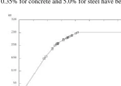
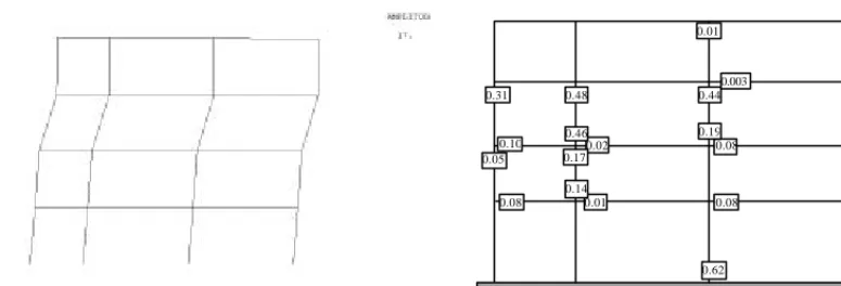
Application to the Ispra 4 Storey Frame
The Hinge Method has been applied to the Ispra 4 storey structure. A mesh made of beam elements has been used for the structure with a cracked Young modulus equal to one third of 32000 MPa (10667 MPa). The computed initial frequency of the model is equal to 0.94Hz. Fig 8 shows the calculated base shear versus top displacement for this building. The maximum global strength at the formation of the mechanism is equal to 250 kN to be compared to the maximum base shear measured during the test (217 kN for the 975 years return period test). The computed failure pattern is shown Fig 9 and is in accordance with the experimental observation since the damage concentrates at the 3rd storey. The damage index is also given for the 975 years return period spectra on Fig. 9. The local failure criteria of 0.35% for concrete and 5.0% for steel have been considered.
Fig. 8 Base Shear-Top Displacement relationship for the Ispra 4 Storey Frame
Table 3. Main numerical results given by the simplified hinge method – Bare frame (cracked stiffness)
475 years numerical
475 years experimental
975 years numerical
975 years experimental (1)
Max. acceleration 2.18 m/s2 2.18 m/s2 2.88 m/s2 2.88 m/s2
Top displacement 67.8 mm 60.8 mm 104 mm 116.7 mm
Base shear 219 kN 209 kN 250 kN 217 kN
Drift at 4th storey 0.2% 0.46% 0.31% 0.91%
Drift at 3rd storey 0.89% 0.79% 1.37% 2.41%
Drift at 2nd storey 0.78% 0.73% 1.20% 1.03%
0.62 0.08 0.08 0.44
0.02
0.08 0.01
0.10 0.48
0.003
0.37
0.46
0.01
0.29 0.13
0.10
0.06 0.17
0.14 0.05
0.31
0.19
Fig 9. Deformed shape after formation of the mechanism and damage index θθ/θθu for the 975 years spectra
CONCLUSIONS
The present paper gives some general consideration about the application of non linear modeling to the seismic assessment of existing reinforced concrete buildings. Two different modeling approaches have been applied to the study of a 4 storey reinforced concrete frame.
On one side, time history analysis have been conducted with a non linear fibre type beam element and have shown the capability of such modeling to reproduce the complex physical phenomena which can occur during a seismic loading. These non linear models allow to estimate the local flexural ductility demand and check the shear demand in the main structural members.
On the other side, a simplified hinge method is described and applied to the same structure. Its robustness and its simplicity make it very attractive for the seismic assessment of existing facilities which can have a complex geometry. This method very similar to a push over analysis reduces the problems linked to the choice of the seismic input for the non linear analysis since an elastic spectra is considered.
The good agreement between numerical and experimental results must not make forbidden the difficulties in the definition of the damage index: what can be defined as failure ?, for which level of damage are designed the structures such as the nuclear facilities ? Furthermore the lack of common rules for the seismic assessment make problematic the choice of some modeling parameters such as the damping matrix, the strength of the brittle failure mechanisms, the influence of the construction details on the modeling parameters, etc…
Finally the two approaches applied to the study of the 4 storey building remain deterministic. A next step is to determine the fragility curve of the structure and compute a failure probability by convoluting fragility and seismic hazard. Although this approach is very attractive in term of safety analysis, one must not forget the problem carried out by the new parameters to introduce: enough experimental results are they available to determine the density of probability of local failure ?
ACKNOWLEDGEMENT
A part of this work and the experimental campaign have been performed within the ICONS and ECOEST II European Projects. The authors would like to acknowledge, for their support and the experimental results, Dr. A. Pinto and P. Pegon from JRC Ispra and Dr. E. Coelho and C. Carvalho from LNEC Lisbon.
REFERENCES
1. Millard A., CASTEM 2000, Manuel d’Utilisation, CEA -LAMS Report N° 93/007, Saclay, 1993 2. Combescure D., Pegon P., Application of the local-to-global approach to the study of infilled frame structures under seismic loading, 12th World Conference on Earthquake Engineering, Auckland, New Zealand, 2000.
3. Combescure D., Sollogoub P., Bouchon M., Deleruelle F.. Local and global modelling of the NUPEC R/C Shear wall under seismic loading. 11th Earthquake Engineering European Conference, Paris 1998.
4. Pegon P., A Timoshenko simple beam element in Castem 2000, JRC Technical Note N°I.93.05, Ispra, 1993. 5. Guedes J., Seismic behaviour of reinforced concrete bridges, Numerical analysis and experimental assessment, PhD thesis, Univ. of Porto, 1997.
7. FEMA, FEMA 273-NEHRP Guidelines for the Seismic Rehabilitation of Buildings », Federal Emergency Management Agency, 1997.
8. Griffith M.C., Pinto A., Seismic retrofit of reinforced concrete buildings. A review and case study, 12th World Conference on Earthquake Engineering, Auckland, New Zealand, 2000.
9. Calvi G.M, Recla M, Assessment of current prediction capacities of the response of existing reinforced concrete buildings, , 12th World Conference on Earthquake Engineering, Auckland, New Zealand, 2000.