Multi Frequency RFID Read Writer System
Uppala Sunitha1, B Rama Murthy2, P Thimmaiah3, K Tanveer Alam1
PhD Scholar, Department of Electronics, Sri Krishnadevaraya University, Anantapur, A.P, India1
Professor, Department of Instrumentation, Sri Krishnadevaraya University, Anantapur, A.P, India2
Assistant Professor, Department of Electronics, Sri Krishnadevaraya University, Anantapur, A.P, India3
ABSTRACT:
A multi frequency RFID reader/writer system is capable of identify different tags which are operatingat multi frequencies simultaneously. The unavailability of a dedicated read/writer for all rfid tags has created a bottleneck in expansion of the rfid market. The present system can be able to support most regularly used frequencies in the RFID world. The reader includes a radio frequency modulation and demodulation for each operating frequency of the tags and these modules are integrated and interfaced to microcontroller. Each of the radio frequency module receives the signal from the tags with associated operating frequency and converts the return signal into a pulse sequence which is detected by the controller, it locks the pulse sequence and decodes the data according to the protocol associated with the tag.
KEY WODS: Multi frequency, RFID read/writer, tag,
I. INTRODUCTION
The RFID reader identify the objects to be labeled with tags. When the tag is passed through the electromagnetic field of a reader the object can be identified [1] by reading the tagged object. Radio frequency identification systems provide a number of advantages over paper and ink labels such as bar code systems in that a much greater degree of automation is permitted clear line of sight is not required, reading distances can be greater, tags can be hidden either to protect the tag from damage in use or for security reasons.
At present different types of tags named as passive, active, read only and read write tags. There is an enormously wide variety of tags that may be used or required by an application making it very hard to have one reader handle all tag types. Typically there would have to be a specific reader matched to the specific properties of each type of tag being used in the application. Hence, a generalized RFID reader/writer is required to deal with different popularly used RFID frequencies in the market.
The tag includes an antenna, which could be a dipole for far field systems or a coil for inductive systems tuned to the frequency of the interrogator's generated electromagnetic field. The electrical current thus generated in the tag's antenna is used to power the tag. Data is generally sent to the tag by modulating this reader generated electromagnetic field. The tag can send data back to the reader either by transmitting with its own transmitter with a separate frequency and antenna from the effected field commonly called a back scatter system. The data from the tag is thus decoded, thereby enabling the tag and the item to which the tag is attached to be identified. In general radio frequency identification tags available in different free band frequencies which are 100-200 KHz, 13.56 MHz, 450-869-917 MHz and 2.45 GHz. They have different physical properties which make the tags suitable for specific applications and environments.
frequencies. The present work provides a reader/writer for a radio frequency identification system which is suitable for use with tags operating at different frequencies.
II. HARDWARE
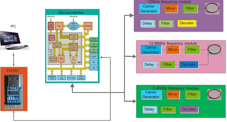
Figue1 shows the complete block diagram of multi frequency RFID reader/writer system. In the present work provides read/ write for a radio frequency identification system which is suitable for use with tags operating at different frequencies. The reader/writer system divides the problem of multiple frequency rfid read writer into two stages. The first stage is characterized by carrier frequency and the second one is characterized by the tag operating parameters. There are three principal frequency bands that are in common use today and each of these bands, on its own, requires its own antenna configuration, transmitter and receiver appropriate to the frequency of operation. This frequency dependent element is referred to as a radio frequency module.
In the second stage is the tag operating parameters like data rate, length of message and encrypting are considered as computational problems. This can be handled by another component referred to as the microcontroller module. This module either directly calculates the parameters from the incoming tag signal, such as data rate, message length and encrypting. The results of the parameter determinations are verified against a list of acceptable tag parameter combinations before passing on the decoded data as a valid message.
Figure 1: Multi frequency rfid read writer.
The first frequency band, i.e. 100-200 KHz. is suitable for tagging containers and also for the human body. The first frequency band is suitable only for short ranges, typically less than one meter. The first frequency band is only capable of very low data rates and therefore provides poor performance in applications requiring multiple tags to be read in the radio frequency field at the same time.
I. 125 KHZ FREQUECY MODULE
First (125khz) radio frequency module being connected with its own frequency band and having a transmitter and a receiver, the transmitter of the first radio frequency module constructed to send an output signal having a carrier frequency within the frequency band related to the first radio frequency module. The receiver of the first radio frequency module constructed to receive a return signal related with frequency band of the first radio frequency module then demodulated signal is send to the filter then decoder and these decoded signal is given to the port of microcontroller [2]. The 125 kHz is regularly used for low distance [3] if we want to increase the power of the carrier we can use for long distances.
II. 13.56 MHZ FREQUECY MODULE:
The second frequency band 13.56 MHz is commonly used for near field communication [4]. Second (13.56mhz) radio frequency element being connected with its own frequency band and having a transmitter and a receiver, the transmitter of the second radio frequency module constructed to send an output signal having a carrier frequency within the frequency band related with the second radio frequency module, the receiver of the second radio frequency module constructed to receive a return signal related with frequency band of the second radio frequency module[5] as shown in the figure1.
III. 2.45 GHZ FREQUECY MODULE
The third band is 2.45 GHZ can support very high data rates so it is suitable for multiple tags operating in the radio frequency field. Also very small antenna is needed which results in a small footprint for the tag. Third (2.45ghz) radio frequency module [6, 7] being connected with its own frequency band and having a transmitter and a receiver, the transmitter of the Third radio frequency module constructed to send an output signal having a carrier frequency within the frequency band related with the Third radio frequency module, the receiver of the Third radio frequency module constructed to receive a return signal associated with frequency band of the third radio frequency module.
IV. ANTENNA
Antenna chosen consists of only LC. Here the value of L and C is decided by the equation F = 1/2π√LC, Here F is the fundamental frequency (in Hertz), L is inductance and C is capacitance. A high Q- Factor indicates an antenna that is very narrow in frequency, that is, very narrow in frequency i.e. highly selective [8]. This may be good in order to reject interfering signals that would be detected by the antenna. To achieve maximum distance between the RFID Tag and reader (between Tag and reader's antenna-coil) the calibration of the coil is done by using LCR meter.
V. MICROCONTROLLER
In the present work the Atmega1284p is used as processing device which is a low-power CMOS 8-bitmicrocontroller based on the AVR enhanced RISC architecture. The ATmega1284P consisting 16/32/64/128Kbytes of Programmable Flash with Read-While-Write capabilities,512/1K/2K/4Kbytes of EEPROM, 1/2/4/16Kbytes of SRAM, 32general purpose I/O lines, Real Time Counter (RTC), three flexible Timer/Counters with compare modes and PWM, 2 USARTs, JTAG [9] a byte oriented 2wire Serial Interface, a 8channel, 10bitADC with optional differential input stage with programmable gain, programmable Watchdog Timer with Internal Oscillator, an SPI serial port.
connected one of the I/O ports of the microcontroller. After converting the data is send to the serial port of the controller with specific bard rate.
VI. FT232R
The FT232r is used to convert USB to serial interfacing integrated circuit. Due to full integration few external components are sufficient. It support rs232, rs422 and rs485 converting levels. The FT232R adds two new functions compared with its predecessors, effectively making it a "3-in-1" chip for some application areas. The internally generated clock (6MHz, 12MHz, 24MHz, and 48MHz) can be brought out of the device and used to drive a microcontroller or external logic. A unique number is burnt into the device during manufacture and is readable over USB, thus forming the basis of a security dongle which can be used to protect customer application software from being copied. The FT232R is available in different packages those are 28-Lead SSOP, QFN-32 and Pb-free compact. Ft232r is having TX and Rx pins these pins are connected to RX and TX pins of the microcontroller. The drivers activated corresponding port number selected in the pc.
VII. PC
Fig2: GUI Panel for Multi frequency RFID Read/Writer Fig3: GUI Display panel for EHR System
III. RESULTS AND DISCUSSION
The hardware of the system is integrated and implemented successfully with graphical user inter face (GUI) developed in MATLAB. The present system is fruitfully tested on some applications like electronic health record system, vehicle identification and authentication and shopping trolley.
REFERENCES
1. Avoine, G. (2006). Security and Privacy in RFID Systems Bibliography. Available at:
http://lasecwww.epfl.ch/~gavoine/rfid/. (Last Accessed: March 11, 2006.)
2. Sumi lee “Efficient Authentication for low cost RFID system”, computational science and its applications-ICCSA 2005 volume 3480 of the series pp619-627.
3. MR.Rohannitinpradhan, “125 kHz rfid system”, ISSN: 0975 – 6779| NOV 12, volume– 02, issue – 02, journal of information, knowledge and research in electronics and communication engineering.
4. JuSeong Kim ; Dept. of Electron. Eng. “A design of transceiver for 13.56 MHz RFID reader using the peak detector with automatic reference voltage generator and voltage limiter”, SoC Design Conference (ISOCC), 2010 International, ISBN: 978-1-4244-8633-5, pg.no: 287 - 289
5. Yaghjian, A.D, “An overview of near-field antenna measurements”, Antennas and Propagation, IEEE Transactions on (Volume: 34, Issue: 1), pg.no30 – 45
6. A.P.Adsul, “electronic identification system using RFID”, ISSN (e) 2250–3005, Volume 05 Issue, 05 May2015 International Journal of Computational Engineering Research (IJCER).
7. Shunyu-shi, “A design of Active rfid tags based on nrf24l01”, 978-1-4799-2446-2, IEEE.
8. Y. Lee, “Antenna Circuit Design for RFID Applications,” Microchip Technology Inc., Application Note AP710, 2003.