ISSN(Online) :2319-8753
ISSN (Print) : 2347-6710
I
nternational
J
ournal of
I
nnovative
R
esearch in
S
cience,
E
ngineering and
T
echnology
(An ISO 3297: 2007 Certified Organization)
Vol. 4, Issue 10, October 2015
Speech Recognition and Sensor Based
Automatic Firebot
Srishti Khare 1
U.G. Student, Department of Electronics and Communication Engineering, BMS Institute of Technology, Avalahalli,
Bangalore, India1
ABSTRACT: This paper demonstrates the research and implementation of voice automated fire extinguisher vehicle.
The vehicle is turned on and off through connected speech input. The robot navigates using IR transmitter and receiver sensors. The fire is sensed using a thermistor based circuit and gas sensor. The fire is then extinguished by sprinkling water over the affected area. The proposed robot is capable of controlling fire, avoiding obstacles during movement and understanding the meaning of speech commands. The speech recognition system is trained in such a way that it recognizes defined commands and the designed robot navigates using the input from the various sensors used. The advantages of speech activated and automatically operational robots are hands- free and fast data input operations.
KEYWORDS: IR sensor; Thermistor sensor; Gas sensor; Microcontroller; Speech recognition system; Interface.
I. INTRODUCTION
The project aims at designing a cost- effective intelligent, voice operated and automatic fire extinguishing robotic vehicle which can be controlled wirelessly through IR communication. The robotic vehicle is initiated and terminated by the voice command. The proposed vehicle has a water jet spray which is capable of sprinkling water, intended to put off fire in the affected area to provide relief. In this paper we will explain about prototype system which can autonomously detect and extinguish fire accidents.
This robot has a jet spray, fixed in a particular direction, for combating fire whenever a sensor senses smoke or fire and uses a speech recognition system. The device is controlled by a microcontroller.
A voice recognition unit is mounted onto the body of the vehicle to ensure that activation and deactivation operations of the Firebot are performed by voice command. It needs an input as speech to start any movement of the robot. The voice recognizing software compares the immediate input voice with already stored voice, and if the match is found, the robot either turns on or off, according to voice command, otherwise it gives an error message. The program of the project is written in Embedded C language.
Our project controls left (set as default) movement of the robot automatically. The microcontroller takes command from the speech recognition module and drives the relay.
Our motivation for designing this robotic vehicle is to make sure that fire emergencies are dealt with in no time to reduce the harm they may cause.
(a)
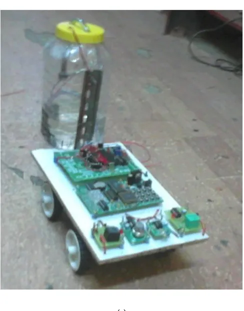
Fig. 1. (a) Working prototype of the Firebot
Fig. 1. (a) depicts the prototype built for this project. The construction of the body of the Firebot has been done in a cost- effective manner.
II. OBJECTIVES
The main objective is to design an economical robotic vehicle which provides safety from fire hazards reducing human efforts. It is aimed to design an automatic fire fighting robot that starts just on a speech command and works without any remote control. The robotic vehicle is desired to have an obstacle detection capability. The robot is expected to have fire and smoke detection attributes to make it useful for industrial purpose.
III. METHODOLOGY
ISSN(Online) :2319-8753
ISSN (Print) : 2347-6710
I
nternational
J
ournal of
I
nnovative
R
esearch in
S
cience,
E
ngineering and
T
echnology
(An ISO 3297: 2007 Certified Organization)
Vol. 4, Issue 10, October 2015
(a)
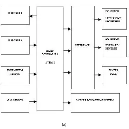
Fig. 2. (a) Functional Block Diagram
The functional block diagram described in Fig. 2. (a) Explains the flow of the working of the Firebot. Upon receiving inputs from the IR sensors, thermistor sensor and gas sensor, the microcontroller then, based on these input values, controls the movement (via DC motors), task of extinguishing fire (via water pump) or initialization/ termination of the vehicle (via voice recognition system).
1. AT89s52 MICROCONTROLLER:
The AT89S52 is a low-power, high-performance CMOS 8-bit microcontroller. The microcontroller in this project controls all the peripherals such as DC motors, gas sensor, temperature sensor, speech recognition system, pump, and hence forms the “brain” of the firefighting vehicle.
2. SPEECH RECOGNITION SYSTEM:
The speech recognition system is a completely assembled and easy to use programmable speech recognition circuit. Programmable, in the sense that you train the words (or vocal utterances) you want the circuit to recognize. It has 8 bit data out which can be interfaced with any microcontroller.
Features
- Self-contained standalone speech recognition circuit
- User programmable
- Up to 20 word vocabulary of duration two second each
- Multi-lingual
- Non-volatile memory back up with 3V on- board battery will keep the speech recognition data in memory
even after power off
(a)
Table. 1. (a) Specifications
The specifications provided (Refer Table. 1. (a)) enable the use of speech recognition system module in some of interfacing applications such as controlling home appliances, robotics movements, Speech Assisted technologies, Speech to text translation, and many more.
3. TEMPERATURE SENSOR:
IC LM 324 is used as an op-amp in the temperature sensor circuit. It works as a comparator and continuously compares the surrounding temperature value with the room temperature one. Until no difference in the two values is found, the robot keeps moving as the microcontroller supplies voltage via relay to all the four dc motors. Once the difference in the temperature values is detected, the relay gets activated. When the relay is activated, it produces low voltage which causes the microcontroller to stop supplying voltage to the dc motors of the robot and supply voltage to the water pump which then sprinkles water over the affected area.
4. IR SENSOR:
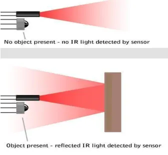
The IR sensor is used for the movement of the robotic vehicle. While in motion, the robotic vehicle will transmit IR waves in the direction of its movement and will identify an object in its path if it receives the reflected IR waves from the object, and accordingly will change its direction of movement (in this case, turn left).
(a)
Fig. 3. (a) Working Principle of IR Sensor
ISSN(Online) :2319-8753
ISSN (Print) : 2347-6710
I
nternational
J
ournal of
I
nnovative
R
esearch in
S
cience,
E
ngineering and
T
echnology
(An ISO 3297: 2007 Certified Organization)
Vol. 4, Issue 10, October 2015
TRX, the vehicle roams about the area, dodging obstacles in its path, and extinguishes fire.
- IR TRANSMITTER-
Infrared transmitter is used to transmit the IR range light wave for communication. IC 555 is used as a stable multi vibrator which generates a frequency in the range of IR Frequency (40 kHz) and feeds it to the transistor. The transistor amplifies the IR signal and drives the signal through the IR Diode. Resistors are used to provide DC biasing to the IC and transistor. Capacitors are used for providing triggering pulse. They also work as filter and generate a frequency in the range of IR level (infrared radiation).
- IR RECEIVER-
The IR receiver is used to detect the reflected IR signal. This signifies the presence of obstacle in the path of movement of the robot. Whenever the robot senses an obstacle it sends a signal to the microcontroller and two of the geared motors stop and the robot turns in a particular direction as programmed. The IR transmitter and the receiver together control the movement of the robot.
5. GAS SENSOR:
The module uses MQ6 sensor to sense gas leakage. It's ready to run circuit with no additional circuitry. Corresponding to the concentration of the gas, it provides both analog and digital output. The output interface from the sensor module can be connected to the microcontroller for wider range of sensor reading. The MQ-6 can detect gas concentrations anywhere from 200 to 10000ppm. The sensor's output is an analog resistance. When the gas is detected then output LED indicator will glow. The output interface from the sensor module can be connected to ADC of a microcontroller for wider range of sensor reading.
Specification
- Power supply needs: 5V
- Interface type: Analog
- Pin Definition: 1-Output, 2-GND, 3-VCC
- High sensitivity to LPG, iso-butane, propane
- Small sensitivity to alcohol, smoke
- Fast response
- Stable and long life
- Size: 40x20mm
6. DC MOTORS:
Permanent magnet DC motors are used which operate at 12V with a speed of 150 rpm. The DC motors have a low cost, are durable and run at an adequate speed as per our requirement.
7. WATER PUMP:
The water pump is loaded at the rear end of the robotic vehicle to balance the weight to allow efficient movement of the Firebot. The water pump for this prototype is a plastic bottle with a nozzle at the end of the pipe that sprinkles out water at the rate of 152mm/h.
IV. SCOPE
By making it GPS enabled, the system can be controlled from remote station also. A CO2 booster can be attached to make the system a powerful extinguisher where water need not be used to extinguish fire. This finds application in electric fire hazards. The robot can be made fully voice operated just by introducing a camera for navigation in the design, thus enabling video capturing feature.
V. PROBLEM DEFINITION
In industries, it takes time for the fire to get detected and a great amount of damage can take place till then. Also, sometimes human intervention is not possible, as in the case of a severe fire scenario. Keeping these issues in view, a voice operated fire extinguisher robotic vehicle is designed. Its small size makes it efficient to get into smaller areas and combat fire efficiently. The detection of fire is faster with this robot. Also the fact that it does not require constant human navigation makes it more efficient.
VI. SOFTWARE DETAILS
In this project we need to program the microcontroller so that the robot can perform the necessary operations needed to implement the required application. To do this, we have used two types of software:
1. Keil Integrated Development Environment [Keil µVision3]
2. Atmel 89 series Flash Programmer version 3.1
The Keil µVision3 is used to write the actual Embedded C program and built the target file as a .hex file. Then, the Flash Programmer, which is a hardware device interfaced to a PC using an LPT1 port (parallel port) is used along with accompanying software to convert the .hex file into a binary file that is used to program the microcontroller by using the flash programmer hardware.
(a)
Fig. 4. (a) Configuring Flash tools to specify Clock frequency and .hex file format
Steps to create the .hex file are (Refer Fig. 4. (a)): 1. In a new µVision project, add the .c file (the program in Embedded C). 2. Save this project and .c file in the target folder. 3. Go to flash and then configure flash tools. 4. In the target tab, specify the XTAL frequency as 11.0592 Mhz. 5. In the Output tab, click on create .hex file 6. Then, in main program, build target. If there are no errors, a .hex file will be created where the project is stored. This hex file is the required input to the Flash Programmer.
(a)
Fig. 5. (a) Atmel Parallel Programmer
ISSN(Online) :2319-8753
ISSN (Print) : 2347-6710
I
nternational
J
ournal of
I
nnovative
R
esearch in
S
cience,
E
ngineering and
T
echnology
(An ISO 3297: 2007 Certified Organization)
Vol. 4, Issue 10, October 2015
VII. SOFTWARE DESIGN
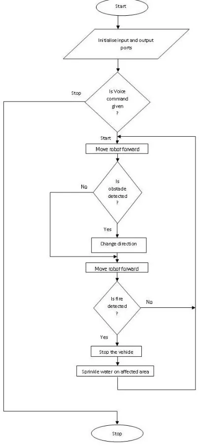
Following is the flow diagram based on which the code is written in C++ language, which is then dumped into the microcontroller.
The flow of the code is based on the actions the firefighting robot, aka, “firebot” will be performing in a fire occurring scenario.
(a)
VIII. HARDWARE DESIGN
The robotic vehicle is designed in a cost effective manner. The hardware construction of the Firebot can be observed in figure 1. As can be seen, four DC motors are mounted to enable movement. The water pump is fixed inside a plastic jar, which sprinkles water onto the fire affected area.
IX. CONCLUSION
The designed robot is capable of efficiently extinguishing fire and replacing human efforts to do the same. Its movement is based on the obstacles in its path. This fire- fighting robot quickly detects the fire or smoke and sprinkles water over the affected area. The prototype presented in this paper has a high scope in industrial applications as well as in inaccessible areas.
X. TESTING CONDITIONS
The main challenges and hurdles we faced in designing and implementing the Fire Fighting Robot were with respect to the code written in Embedded C and the design of the robotic vehicle. The water pump loaded at the back of the vehicle was making it difficult to turn the vehicle left upon facing an obstacle.
For the purpose of demo using the prototype we have created, we used a candle to depict a fire scenario and the Firebot sprinkled water in that direction. We brought the candle in close proximity with the thermal sensor. To depict the movement of the Firebot, we placed an obstacle such as a book in the line of movement of the vehicle and observed the Firebot change its direction of movement (i.e. turn left).
REFERENCES
1. Theodoridis, T.; Huosheng Hu, "Toward Intelligent Security Robots: A Survey", IEEE Transactions on Systems, Man and Cybernetics: Systems. , vol.42, no.6, pp.1219-1230, Nov. 2012.
2. Young-Duk Kim; Yoon-Gu Kim; Seung-Hyun Lee; Jeong-Ho Kang; Jinung An, "Portable fire evacuation guide robot system", IEEE/RSJ International Conference on Intelligent Robots and Systems., vol., no., pp.2789-2794, 10-15 Oct. 2009.
3. Helms, E.; Schraft, R.D.; Hagele, M., "rob@work: Robot assistant in industrial environments", IEEE International Workshop on Robot and Human Interactive Communication., vol., no., pp.399-404, 2002.
4. Riccardi, G.; Hakkani-Tur, D., "Active learning: theory and applications to automatic speech recognition", IEEE Transactions on Speech and Audio Processing., vol.13, no.4, pp.504-511, July 2005.