SENSITIVITY OF THE HIGH FREQUENCY ACPD TECHNIQUE FOR
THE DETECTION OF SURFACE DAMAGE AND CRACKS DURING
CREEP
Mustafa Nasser1, Catrin M. Davies2, Kamran Nikbin3, and David W. Dean4
1 EngD Research Engineer, Department of Mechanical Engineering, Imperial College London, UK
2 Lecturer, Department of Mechanical Engineering, Imperial College London, UK
3 Professor of Structural Integrity, Department of Mechanical Engineering, Imperial College London, UK 4 High Temperature Specialist, EDF Energy Nuclear Generation Ltd, UK
ABSTRACT
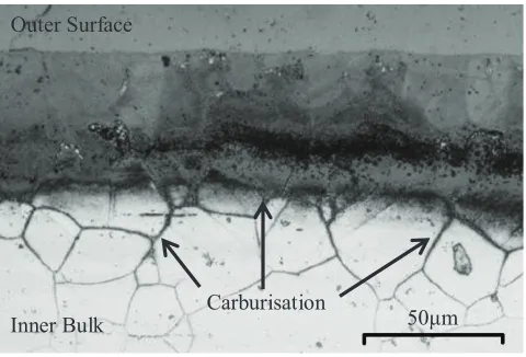
!"#$%&'$(&")&*$&+",%"-./"-0&)1234"560'&)4',0"7"809"5$0:#&2";,$0'"7")&8<',)4"=84"$9&0'$%$&9"'=&"<)8<:$01" of critical boiler components, posing a significant risk to future operation. The components are fabricated from 316H steel and operate in CO2 environments under high temperature (550°C) creep conditions. As a result, it has been discovered that a hardened outer surface layer forms through carburisation mechanisms. The addition of this layer is thought to be detrimental to the creep-fatigue and fracture properties of 316H, causing premature surface cracking that is propagating and damaging components. The ability to detect the presence of this surface cracking is crucial as it underpins our ability to predict the failure of components.
This paper focuses on the development of a high frequency alternating current potential drop (ACPD) monitoring system to assist in the detection of surface crack initiation during creep. A primary aim of our work is to develop the ability to monitor surface cracking, in order to provide an insight into the carburised materials true failure mode and behaviour. Experimental results and findings from application of the ACPD technique to preconditioned plasma-nitrided tensile specimens are presented within this paper. The response of the system to surface cracking through nitrided material has been predicted through a series of finite element models and comparisons with experimental data are made. It is expected that this work will contribute to improved understanding in increasing sensitivity of non-destructive monitoring methods for components which are affected by environmental surface oxidation and damage.
INTRODUCTION
The Uni'&9" >$019,(34"increasing energy demand has led to the decision to extend the lifetime of its aging fleet of AGR 06<#&8)")&8<',)4?"!"#$%&'$(&")&*$&+",%"-./"-0&)1234"560'&)4',0"7"809"5$0:#&2";,$0'" B reactors has identified cracking of super heater steam bifurcation pipes amongst other components. As a result, to mitigate further damage, plant operating temperatures have been lowered reducing operating efficiency and incurring vast financial costs.
23rd Conference on Structural Mechanics in Reactor Technology Manchester, United Kingdom - August 10-14, 2015 Division II
of carburisation on the creep properties of 316H can be accurately predicted to ensure that EDF Energy can perform future component safety assessments with confidence.
Figure 1 Extensive surface hardening as a result of planar and grain boundary carburisation (represented by the darker shaded areas).
For the creation of any assessment methodology, material properties are essential in predicting component lifetimes. Creep properties are usually obtained from accelerated long-term uniaxial creep testing. Unfortunately, these types of test can only provide a measure of averaged bulk specimen properties. In order to evaluate the creep properties of individual surface layers i.e. carburised material, and interaction with the bulk, it is crucial to be able detect damage and cracking within these layers. This often requires the adoption of advanced testing techniques and/or real time non-destructive evaluation (NDE), such as the potential drop (PD) method.
This paper investigates the applicability of the alternating current potential drop (ACPD) technique in detecting surface crack initiation and growth during high temperature uniaxial creep testing. The aim is to be able to successfully detect surface damage in order to improve understanding of the influence of a case-hardened outer layer on specimen creep properties. This can assist in providing an insight into the nature of cracking within carburised reactor components.
The ACPD Technique
PD methods have traditionally been used to measure defect depths within cracked components, specifically in monitoring creep crack initiation, growth and damage (Sposito, Ward, et al., (2010)). Unlike many other NDE techniques PD systems are not restricted to specimen free surfaces and offer the main advantage of being able to monitor during testing.
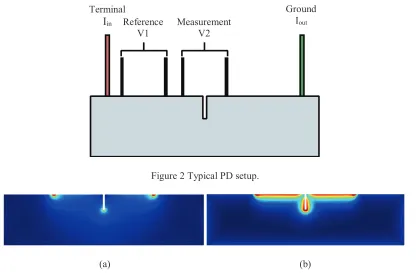
There are two main variations of the PD technique that are defined by the type of current used; these are direct (D.C.) and alternating (A.C.) currents. Both work on a similar principal of evaluating the state or condition of a specimen based on changes of local electrical resistance/impedance caused by the effects of strain, damage and fracture. A typical PD setup is shown in Figure 2, current is injected across the whole specimen via a terminal and ground and a series of monitoring probes are placed either side of a crack or expected crack location. Subsequent crack extension causes a perturbation in current path, thus a change in resistance and increase in potential drop. This is measured and compared alongside a reference A60<)8<:&93"(&846)&(&0'"809"<8#$B)8'$,0" <6)*&4" $0",)9&)"',"&4'$(8'&" ','8#"<)8<:"#&01'=",)"<)8<:" 1),+'=" rate. It is important to normalise data against a reference measurement in order to exclude any changes in PD signal due to variations in experimental setup, temperature and piezoresisitive effects.
CDE(
Outer Surface
Inner Bulk
The primary difference between DCPD and ACPD systems lies within the resulting current density distribution formed within specimens. Whilst DC currents form even current density distributions, AC currents enable the formation of skin effects, causing the current to become focused onto the specimen surface. In short, the skin effect is the tendency of an AC current to distribute itself within the near-surface region of a conductor such that the current density is highest towards the near-surface and decreases sharply towards the centre, Figure 3. The current skin depth is a function of the applied current frequency, specimen electrical conductivity and magnetic permeability (Saguy & Rittel, (2007)). The higher the frequency and/or magnetic permeability, the thinner the skin depth created. This phenomenon can have a great influence on the sensitivity of an ACPD system to surface crack initiation and growth.
Figure 2 Typical PD setup.
(a) (b)
Figure 3 Finite element modelling - current density distributions for the case of DC (a) and AC (b) PD currents demonstrating the influence of the skin effect.
The choice of whether to use an AC or DC PD system is typically based upon the desired application. The resolution of a DCPD system is directly proportion to the magnitude of input current. This presents a problem when attempting to resolve small defects and surface crack initiation. In order to detect small changes in surface cracking, a large input current must be used. Unfortunately, this has the potential to introduce large sources of error through increased current signal instability, localised specimen heating and EMF effects occurring at points of contact and crack tips. The ACPD technique offers an alternative approach. By utilising high frequency input currents, extremely thin skin depths can be created. Since the flow of current will be restricted near the specimen free surface, any surface cracking or damage is far likely to change the potential drop to a greater degree than an equivalent DCPD setup.
High Frequency ACPD ! Surface Crack Initiation
The detection of small cracks and defects within metals using the ACPD technique is well established (ASTM International, (2015)) and has been extensively covered within the literature (Dogan, Nikbin, et al., (2006); Prajapati, Nagy, et al., (2012); Raja, Mahadevan, et al., (2010); Saguy & Rittel, (2005),
Terminal Iin
Ground Iout Reference
V1
23rd Conference on Structural Mechanics in Reactor Technology Manchester, United Kingdom - August 10-14, 2015 Division II
(2007), (2006); Collins, Michael, et al., (1996); Livingstone & Kilpatrick, (1998)). The majority of studies however, appear to be primarily concerned with low-frequency ACPD. The use of high frequency ACPD to detect surface crack initiation has been covered to a much lesser extent. Early studies conducted on developing high frequency systems have been particularly focused on detecting crack initiation within fatigue specimens (Hwang, (1992); Verpoest, Aernoudt, et al., (1980); Dai, Marchand, et al., (1995)). Despite being limited to moderately high frequencies of around 100 kHz (owing to limitations in experimental setup), a good sensitivity to surface crack initiation was found with reports of these systems able to detect a minimum single <)8<:"4$F&",%"CDE(?
These studies however, focused on detecting crack initiation within homogenous specimens containing consistent electrical and magnetic properties across their depth. It is expected that carburisation or any surface preconditioning will have a profound effect on the electrical and magnetic properties of 316H (Gonser, Krischel, et al., (1980); Willis, Bland, et al., (1988); Moruzzi, Marcus, et al., (1986); Menéndez, Templier, et al., (2013); Basso, Pimentel, et al., (2009)). This can be expected to greatly affect PD measurements. Previous studies have investigated application of high frequency ACPD to magnetically inhomogeneous material/surface layers however successful detection of crack initiation has not been observed (Zhang, Bowler, et al., (2009); Hyde, Saber, et al., (2010); Prajapati, Nagy, et al., (2012); Jablonski, (1995)).
EXPERIMENTAL TESTING
Uniaxial Tensile & Creep Testing
A series of high temperature (550°C) uniaxial tensile and creep tests have been conducted on plain and preconditioned round-bar specimens. This was undertaken to confirm that preconditioned specimens would replicate the behaviour of carburised material. In this scenario, it was essential that surface cracking was significant, in order to maximise the potential of the ACPD system for detecting crack initiation.
Specimen Preconditioning
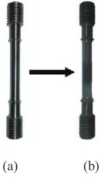
The availability of ex-service carburised material is limited and as such preconditioning of plain 316H was required to simulate the effects of carburisation. Uniaxial round bar specimens were externally preconditioned through a plasma-nitriding regime, Figure 4. In short, plasma-nitriding diffuses nitrogen into steel to create an outer case-hardened surface layer (Basso, Pimentel, et al., (2009); Christiansen & Somers, (2005)) similar to that of carburisation. Although this nitrided layer may possess dissimilar chemical and mechanical properties to that of carburised 316H, nitriding was used to serve as a method to rapidly create test specimens containing a surface layer that is likely to crack before the bulk.
(a) (b)
Specimen Metallography
Section metallography and SEM Fractography have been undertaken on the failed creep specimens, ( Figure 5Figure
7).
Figure 5 shows the presence of widespread surface cracking along the entirety of the nitrided specimen with cracks orientated perpendicular to the direction of load. The nitride layer is clearly defined and is easily viewed as the darker shaded outer region. The majority of cracks have propagated to a depth of GDDE(H"'=&"8@@),I$(ate depth of the hardened layer, with some showing early signs of propagation into the bulk. The plain specimen showed no signs of such cracking with sparse surface damage close to the fracture region as expected.
To further investigate the nature of the surface cracking, both specimens were etched using Ferric Chloride solution (FeCl3) in order to highlight grain boundaries and structures. It is clear from Figure 7 that the nitrided specimen exhibited brittle fracture across the nitride layer, propagating as intergranular fracture into the bulk. In contrast, the sparse surface damage of the plain specimen was purely due to intergranular fracture. SEM fractography undertaken on both specimens confirms this; regions of flat, brittle failure surround the outer edge of the nitrided specimen, Figure 6.
Figure 5!Section metallography of nitrided specimen showing widespread surface cracking and damage.
(a) (b)
23rd Conference on Structural Mechanics in Reactor Technology Manchester, United Kingdom - August 10-14, 2015 Division II
Figure 6 SEM Fractography of plain (a) and nitrided (b) specimens showing clear differences in surface cracking and failure modes.
(a) (b)
Figure 7 Section metallography of plain (a) and nitrided (b) uniaxial creep specimens demonstrating the nature of the surface cracking.
FINITE ELEMENT PREDICTIONS
ACPD Response to Cracking of the Nitrided Layer
In order to predict the response of the ACPD system to the initiation of surface cracking across nitrided specimens, a series of finite element models have been created. Section metallography of failed uniaxial specimens has shown the presence of a thin outer oxide followed by a well-defined nitrogen rich layer. Due to the fact that austenitic stainless steels become partly ferromagnetic after nitriding (Menéndez, Templier, et al., (2013); Basso, Pimentel, et al.H"JKDDLMN"OF'P):"Q"R$##$8(4,0H"JGLLCMM, it is expected that the nitride material has highly variable electrical and magnetic properties throughout its depth. It has been found that this nitrogen rich layer is composed of two separate strata, an outermost ferromagnetic layer followed by an inner paramagnetic layer. This suggests that these layers possess a higher magnetic permeability than the bulk nonmagnetic 316H and thus can encompass smaller current skin depths. This behaviour has been captured within the finite element model as a variation in magnetic permeability across depth. The nitrided material J','8#" 9&@'=" ,%" GDDE(M" +84"composed of two separate layers, each having an arbitrary higher magnetic permeability than that of the bulk.
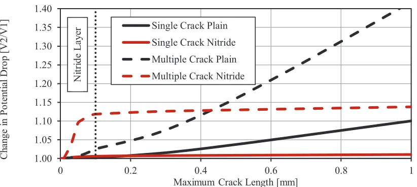
Two scenarios have been modelled: a plain and nitrided specimen. A crack was initiated and propagated throughout each specimen and the change in AC potential drop has been evaluated and compared with that of a reference measurement. The results of both scenarios are presented in Figure 8 with change in potential drop plotted against increasing crack length. For the plain specimen, an initial non-linear increase in potential drop is seen at very small crack lengths that approaches a linear relationship as the crack propagates. In contrast, for the nitrided material, a sharp increase in potential drop is seen due to cracking of the nitrided layer followed by decreased sensitivity to crack propagation within the bulk. More representative of actual nitrided specimens, the model was extended to include multiple widespread initiating surface cracks; a proportion of which were allowed to extend into the bulk material. In a similar manner to the first model, almost identical trends are observed, Figure 8.
Figure 8 FE Change in potential drop as a result of surface cracking for both plain and nitrided specimens.
Finite element modelling of nitrided specimens has shown that surface cracking creates a significant marked change in PD. The results of the FE modelling can be explained as follows. As the nitrided layer cracks, an expected large increase in PD can be seen due to an increase in current path length. However, once cracking begins to propagate into the bulk material the change in PD becomes less significant. This is due to the fact that the bulk possesses a lower magnetic permeability than the nitrided layer; encompassing a larger current skin depth. Thus, any change in crack length within the bulk introduces a much lower increase in resistance hence PD; reducing the overall systems sensitivity to cracking.
HIGH FREQUENCY ACPD TRIALS
Experimental Setup
To investigate the effectiveness of the ACPD method in detecting surface crack initiation a series of high temperature (550ºC) slow strain rate, uniaxial tensile tests were conducted on plain and nitrided 316H round-bar specimens. Samples were setup into a Mayes servo hydraulic tensile testing frame and were slowly strained to failure or until surface cracking could be observed at a constant displacement control of 0.005mm/s. Capacitance gauges were clamped to specimens to provide accurate measurements of strain. All tests were conducted within a high temperature furnace containing a glass window for the observation of surface cracking.
The ACPD setup consisted of a Matelect CGM-7 ACPD unit paired with a National Instruments USB DAQ. A terminal, ground and two sets of probes, each with a different spacing (5mm & 10mm) were attached to specimens through resistive spot welding. Current and probe leads were fabricated from 0.5 mm titanium wire and these were spot welded onto stainless steel studs welded onto each specimen. An AC current of 0.5A at a frequency of 239.987 kHz was chosen for each test. In theory, to maximise the potential to detect surface crack initiation, the highest current frequency should always be chosen (240 kHz for the CGM-7), however it was discovered that slightly offsetting this maximum frequency would greatly reduce the noise of the PD signal. It is thought that this may have been due to the ACPD system becoming in phase will the AC electricity supply at 50 kHz, increasing signal fluctuations.
It should be noted that no reference PD measurement could be made as the nitrided specimens exhibited extensive surface cracking across their entirety. However, from FE modelling, it was expected that the initiation of any surface cracking would cause an almost instantaneous, significant change in PD. Thus, it
1.00 1.05 1.10 1.15 1.20 1.25 1.30 1.35 1.40
0 0.2 0.4 0.6 0.8 1
C h an ge i n P o te n ti al Dr o p [V2/V1]
Maximum Crack Length [mm] Single Crack Plain
Single Crack Nitride Multiple Crack Plain Multiple Crack Nitride
23rd Conference on Structural Mechanics in Reactor Technology Manchester, United Kingdom - August 10-14, 2015 Division II
was expected that under slow-strain rate conditions, any instantaneous significant change in PD could be attributed to surface crack initiation which would be confirmed upon specimen metallography.
Experimental ACPD Results
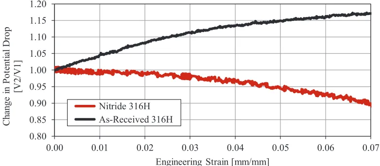
The results of each experiment are presented below with change in potential drop plotted against increasing strain, Figure 9. For the plain specimen, a steady increase in PD was observed with increasing strain. In contrast to this, the nitrided specimen showed a constant decrease in PD. Despite widespread surface cracking observed during testing, no significant changes or deviations in PD signal were seen.
Figure 9 Change in plotted against increasing strain for plain and nitrided tensile specimens.
DISCUSSION
The purpose of this study is to successfully detect the initiation of surface cracking within preconditioned tensile specimens using the high frequency ACPD technique. The data that has been obtained from experimental testing is not consistent with FE predictions and was unsuccessful in evaluating surface crack initiation and growth. The most likely explanation of this result is concerned with the resistivity of the surface layer. It is possible that the nitrided layer possesses a higher resistivity than the bulk. Any surface cracking or damage would perturb the current to flow through the less resistive bulk material thus resulting in a decrease in potential drop. This scenario would only occur however, on the assumption that the increase in current path length due to this cracking would not over shadow the effects of this change in resistivity. It is possible that the accumulation of unobservable micro cracking and damage with the nitrided layer is causing a non-linear decrease in potential drop with increasing strain. In addition to this change in resistance, it has been demonstrated that magnetic permeability is highly influenced by the state of strain of a material. It is possible that there is mismatch between the behaviour of both materials in response to increasing strain which is causing this unexpected reduction in PD.
These findings have a number of possible limitations, namely the inability to obtain a reference measurement for the nitrided material. By normalising both ACPD signals against reference measurements, the effects of stress, strain and other possible variations in experimental setup can be delineated from the data allowing the possible identification of surface crack initiation and growth. Moreover, the high dependence of magnetic permeability and resistivity on stress and strain were not included within FE models as reliable data could not be found to describe these trends for austenitic stainless steels. It is expected that the inclusion of this data would have a significant effect on the resulting modelled PD response.
0.80 0.85 0.90 0.95 1.00 1.05 1.10 1.15 1.20
0.00 0.01 0.02 0.03 0.04 0.05 0.06 0.07
C h an ge i n P o te n ti al Dr o p [V2/V1]
Engineering Strain [mm/mm] Nitride 316H
CONCLUSION
Based on the initial results it can be concluded that further experimental data and analysis is required to fully interpret and understand the response of the ACPD system in the detection of surface cracking. Future work will involve application of the high frequency ACPD technique to actual carburised specimens. Since specimen gauge lengths will be partly carburised, in this case it will be possible to include a reference PD measurement which will assist in data interpretation. Clearly, further study is also required to evaluate the influence of stress and strain on the magnetic signature of 316H in order to create FE models that are more representative of experimental behaviour.
It is hoped this scheme of work will eventually enable the identification of surface cracking within carburised specimens to assist in the evaluation of material properties and data in order to improve component lifetime safety assessments.
ACKNOWLEDGEMENTS
This work has been published with permission from EDF Energy and part funded by TSB Grant TSK004387-1. C. M. Davies acknowledges support from grant EPSRC EPI004351/1.
REFERENCES
ASTM International (2015) E647 - Standard Test Method for Measurement of Fatigue Crack Growth Rates.
Basso, R.L.O., Pimentel, V.L., Weber, S., Marcos, G., et al. (2009) Magnetic and structural properties of ion nitrided stainless steel. Journal of Applied Physics. 105 (12), 124914.
Christiansen, T. & Somers, M. a. J. (2005) Low temperature gaseous nitriding and carburising of stainless steel. Surface Engineering. 21 (5-6), 445S455.
Collins, R., Michael, D.H. & Clark, R. (1996) Measurement of crack depth in a transition weld using ACPD. NDT & E International.29 (2) p.124.
Dai, Y., Marchand, N. & Hongoh, M. (1995) Fatigue crack growth measurements in TMF testing of titanium alloys using an ACPD technique. !"#$%&'()*+,%-()./*)+,%0.
Dogan, B., Nikbin, K., Petrovski, B., Ceyhan, U., et al. (2006) Code of practice for high-temperature testing of weldments. International Journal of Pressure Vessels and Piping. 83 (11-12), 784S797.
EDF Energy (2003) R5 Issue 3: An Assessment Procedure for the High Temperature Response of Structures.
Gonser, U?H">)$4<=&#H">?"Q"T846H"U?"JGLVDM"/&)),(810&'$<",)9&)$01"$0"%<<"W-Fe precipitates in Cu-Au alloys. Journal of Magnetism and Magnetic Materials. 15-18 (PART 3), 1145S1146.
Hwang, I. (1992) A multi-frequency AC potential drop technique for the detection of small cracks. Measurement Science and Technology. 62.
23rd Conference on Structural Mechanics in Reactor Technology Manchester, United Kingdom - August 10-14, 2015 Division II
Jablonski, D. (1995) Measurement of multiple-site cracking in simulated aircraft panels using AC potential drop. ASTM special technical publication.
Livingstone, F. & Kilpatrick, I.L. (1998) On-line fatigue crack growth monitoring in externally pressurised vessels using the alternating current potential drop (ACPD) technique. NDT & E International.31 (1) pp.72S73.
Menéndez, E., Templier, C., Garcia-Ramirez, P., Santiso, J., et al. (2013) Magnetic properties of single crystalline expanded austenite obtained by plasma nitriding of austenitic stainless steel single crystals. ACS applied materials & interfaces. 5 (20), 10118S10126.
Moruzzi, V., Marcus, P., Schwarz, K. & Mohn, P. (1986) Ferromagnetic phases of bcc and fcc Fe, Co, and Ni. Physical Review B. 34 (3), 1784S1791.
OF'P):H"X?"Q Williamson, D.L. (1995) Phase and composition depth distribution analyses of low energy, high flux N implanted stainless steel. Journal of Applied Physics. 77 (8), 3839.
Prajapati, S., Nagy, P.B. & Cawley, P. (2012) Potential drop detection of creep damage in the vicinity of welds. NDT & E International. 4756S65.
Raja, M.K., Mahadevan, S., Rao, B.P.C., Behera, S.P., et al. (2010) Influence of crack length on crack depth measurement by an alternating current potential drop technique. Measurement Science and Technology. 21 (10), 105702.
Saguy, H. & Rittel, D. (2006) Alternating current flow in internally flawed conductors: A tomographic analysis. Applied Physics Letters. 89 (9), 094102.
Saguy, H. & Rittel, D. (2005) Bridging thin and thick skin solutions for alternating currents in cracked conductors. Applied Physics Letters. 87 (8), 084103.
Saguy, H. & Rittel, D. (2007) Flaw detection in metals by the ACPD technique: Theory and experiments. NDT & E International. 40 (7), 505S509.
Sposito, G., Ward, C., Cawley, P., Nagy, P.B., et al. (2010) A review of non-destructive techniques for the detection of creep damage in power plant steels. NDT & E International. 43 (7), 555S567.
Verpoest, I., Aernoudt, E., Deruyttere, A. & Neyrink, M. (1980) An Improved A.C. Potential Drop Method for Detecting Surface Microcracks During Fatigue Tests on Un-notched Specimens. Fatigue & Fracture of Engineering Materials and Structures. 3 (3), 203S217.
Willis, R.F., Bland, J.A.C. & Schwarzacher, W. (1988) Ferromagnetism in ultrathin metastable films of fcc Fe, Co, and Ni (invited). Journal of Applied Physics. 63 (8), 4051.