Realization of PI Controller for Enhanced
Performance on Switch diminished
Three Phase Brushless DC Motor Drive
K Ravi, D.Nagarajan, A.Charles
,Associate Professor, Dept of EEE, Karpagam College of Engineering, Coimbatore, India
Associate Professor, Karpagam College of Engineering, Coimbatore, India
Assistant Professor, Dept of EEE, Karpagam College of Engineering, Coimbatore, India
ABSTRACT:The Brushless DC motors (BLDC) find widespread applications in domestic and industries due to their low and high power density and ease of speed control. To accomplish desired level of performance the motor requires suitable speed controllers. In case of permanent magnet Brushless DC motors, usually control of speed is reached by using proportional integral (PI) controller. Although the conventional PI controllers are widely used in the industry due to their simple control structure and ease of implementation, these controllers pose difficulties where there are some control complexity such as nonlinearity, load disturbances and parametric variations. Moreover PI controllers require precise linear mathematical models. This paper presents a low cost four-switch brushless dc (BLDC) motor drive for commercial applications. The proposed model uses four switches inplace of six switches in the conventional six switch three phase inverter topology. Direct phase current control (DPC) scheme is employed to avoid problems caused by elimination of two power switches. The PI controller is implemented in the developed system to achieve improved performance. The speed, torque and current response of proposed and conventional method is demonstrated and compared via simulation using MATLAB SIMULINK software.
KEYWORDS
:
Brushless dc Motor, Direct phase current(DPC) control, four switch converter, PI controller.I. INTRODUCTION
ARIABLE-SPEED drives employing a pulse width modulation (pwm) voltage-fed inverter, are used for various purposes in consumer products and industrial applications. Although their technical advantages are generally acknowledged, researchers are becoming aware of their cost and are exploring the possibility of cost reduction.
As brushless dc motors have good features as simple construction, high reliability, light electromagnetic pollution, and high power density, they are used extensively in servo systems and low-power drive systems [2],[3]. The performance of the motor has been improved due to great development of power electronics, microelectronics, magnetic performance of magnets, and motion control technology in recent years [8].
The torque ripple generated due to commutation of phase in the four-switch three-phase BLDC motor is discussed [1],[7]. An asymmetric PWM scheme is used in four-switch three phase BLDC motor drive to make six commutations and to produce four floating phases and to detect back EMF. The position of the rotor can be acquired based on the crossing points in controllable phases of voltage. The full commutation
BLDC motor Ia Ib Ic a b c S1 S2 S3 S5 S6 S4 Vd
-Fig. 1. Conventional six-switch three-phase BLDC motor drive system.
BLDC motor Ic Ia Ib c a b VC1 S4 S1 S3 VC2 -+ S2 + -Vd
-Fig. 2. Proposed four-switch converter topology for three-phase BLDC motor drive system.
points are detected in the four switch inverter drive. Therefore extra phase-shifting circuits or interpolation in the software for prediction of other commutation points are not required [5].
Virtual hall sensor signals are made by detection the zero crossing points of the stator terminal voltages. Commutation points immediately follow the developed virtual Hall sensors. Therefore, 30° phase shifting as used in the methods based on back EMF voltage is not required [6].
The four-switch converter topology provides a possibility for the low cost and high performance three-phase BLDC motor drive system and development of the proper PWM control strategy can be done with the reduced parts converter [4]. Vd a b c s1 s2 s3 s4 n R a b s1 s2 s3 s4 R Vd Vd c n (a) (b)
a b s1 s2 s3 s4 R Vd Vd n a b s1 s2 s3 s4 R n Vd Vd c (c) (d)
Fig. 3. Voltage vectors of four-switch converter. (a) (0, 0) vector, (b) (1, 1) vector, (c) (1, 0) vector, and (d) (0, 1) vector.
of the six switches, as shown in Fig. 2. Compared with the four-switch converter for the induction motor [1], it is identical for the topology point of view.
In the four-switch converter, the generation of 120 conducting current profiles is inherently difficult due to its limited voltage vectors. This problem is well known as “asymmetric voltage pwm.” It means that conventional pwm schemes for the four-switch induction motor drive cannot be directly used for the BLDC motor drive. Therefore, in order to use the four-switch converter topology for the three-phase BLDC motor drive, a new control scheme should be developed. The solutions can be obtained from a modification of the conventional voltage controlled pwm strategies, such as the space vector pwm. However, it naturally requires lots of equations for the transformation of voltage and current vectors, such as α-β and a-b-c frames. As a result, the current control block becomes much more complicated. Moreover, in order to handle the complicated calculations in one sampling period, a high-speed digital processor is also necessary, which increases the manufacturing cost. Therefore, for the low cost BLDC motor applications, voltage vector pwm schemes cannot be regarded as a good solution for cost effective purpose. In this paper, a novel pwm control technique based on the current controlled pwm method is used, instead of the voltage controlled pwm. The developed direct current controlled pwm method is not grounded on a bunch of equations, but on detailed observation of the overall operation, it dramatically reduces equations from the conventional control scheme and is simple to implement from the hardware and software points of view. Therefore, based on the direct current controlled pwm, the four-switch three-phase BLDC motor drive could be a good alternative to the conventional six-switch counterpart with respect to low cost and high performance. The theoretical operating principle of the four-switch converter for the three-phase BLDC motor drive and the proposed pwm control scheme are explained as follows.
II. FOUR-SWITCHTHREE-PHASEBLDCMOTORDRIVE
A. Four-Switch Converter Investigation for BLDC Motor Drives
A BLDC motor needs quasi square current waveforms, which are synchronized with the back-EMF to generate constant output torque and have 60° non conducting and 120° conduction regions. Also, at every instant only two phases are conducting and the other phase is inactive. However, as mentioned earlier, in the four-switch converter, the generation of 120 conducting current profiles is inherently difficult. This can be explained as follows:
In the four-switch configuration, there are four switching status as shown in Fig. 3, such as (0, 0), (0, 1), (1, 0), and (1, 1), in which load the switches are replaced by simple ideal switches and the motor load is replaced by a resistive. “0” means that the lower switch is turned on and “1” the upper switch is turned on. The two switches never turn on and off at same instant. In the case of the six-switch converter, switching status (1, 1) and (0, 0) are regarded as zero-vectors, which cannot supply the dc-link voltage to the load, so that current cannot be flow through the load.
However, in the four switch converter, one phase of the motor is always connected to the midpoint of the dc-link capacitors, so that flow of current is even at the zero-vectors, as shown in Fig. 3(a) and 3(b). Moreover, in the case of (0, 1) and (1, 0), the phase which is connected to the dc-link capacitors midpoint is uncontrolled and only the resultant current of the other two phases flow through this phase.If the load is ideally symmetric, there is no current in the (1, 0) and (0, 1) vectors.
As a result of the operation using four switching vectors, one can represent the phase voltage or current waveforms as shown in Fig. 4. From Fig. 4, it is noted that obtaining the 120 conduction and a 60 non conducting period current profile is difficult based on the “asymmetric voltage pwm.” It means that conventional pwm schemes for the four-switch induction motor drives cannot be used directly for BLDC motor drives.
Fig. 4. Voltage and current waveforms of four-switch converter based on four switching vectors.
B. Operational Principle of Direct Current Controlled PWM
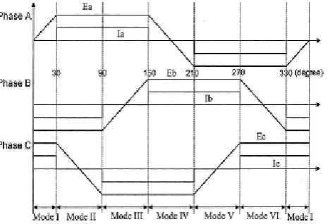
From the motor point of view, even though the BLDC motor is supplied by the four-switch converter, ideal back EMF of three-phase BLDC motor and the desired current profiles can be described as shown in Fig. 5. From the detailed investigation of the four-switch configuration, back-EMF and current profiles, the pwm control strategy can be arrived for the four-switch three-phase BLDC motor drive as follows:
Under a balanced condition, the three-phase currents satisfy the following condition:
Ia
Ib
Ic
0
(1) Then, (1) can be modified as
Ic
(
Ia
Ib
)
(2)In the case of the ac induction motor drive, at any instant there are always three phase current flowing through the load, such as
0
Ia
,Ib
0
,Ic
0
(3)However, incase of the BLDC motor drive, (3) is not valid anymore. Note that in Fig. 5 only phase C is uncontrollable and phase A and B currents are controllable. According to the operating modes, one can derive the following current equations can be derived based on Table I, a switching sequence using four switches can be developed as follows:
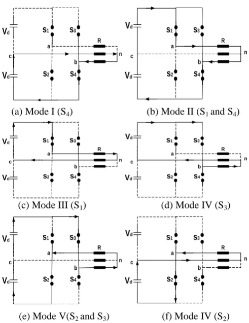
In BLDC motor, such as phase, only two phases needed to be controlled, not three phases. Therefore, the two-phase currents need to be directly controlled using the hysteresis current control method by four switches. Hence, it is called the direct current controlled pwm scheme. Based on the direct current controlled pwm, switching sequence implementation and current flow are depicted in Fig. 6.
Table I
Detailed Current Equations According To The Operating Modes
Mode I (-30<θ<30) Ib+Ic=0 and Ia=0
Mode II (30<θ<90) Ia+Ib=0 and Ic=0
Mode III (90<θ<150) Ia+Ic=0 and Ib=0
Mode IV (150<θ<210) Ib+Ic=0 and Ia=0
Mode V (210<θ<270) Ia+Ib=0 and Ic=0
Mode VI (270<θ<330) Ia+Ic=0 and Ib=0
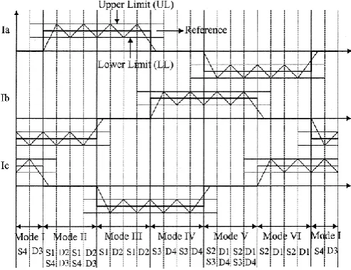
C. Current Regulation
Based on the switching sequences, the current regulation is performed by using hysteresis current control. The purpose of regulation is to shape quasi square waveform with acceptable switching (ripple) band. The switching sequences and detailed waveforms are described in Fig. 7. The bold line is the current reference value, which is obtained from the speed control loop and torque to achieve the reference torque.
The torque ripple and switching frequency are the main considerations for setting the lower and upper limits. It means that a smaller band causes higher switching frequency, but lower torque ripple.
a b c s1 s2 s3 s4 R Vd Vd n a b s1 s2 s3 s4 R n Vd Vd c
(a) Mode I (S4) (b) Mode II (S1 and S4)
a b c s1 s2 s3 s4 R Vd Vd n a b s1 s2 s3 s4 R n Vd Vd c
(c) Mode III (S1) (d) Mode IV (S3)
a b c s1 s2 s3 s4 R Vd Vd n a b s1 s2 s3 s4 R n Vd Vd c
(e) Mode V(S2 and S3) (f) Mode IV (S2)
Fig. 6. Implementation of the direct current controlled PWM strategy.
Using mode II and mode III, current regulation can be explained as follows: In mode II, Ia and the currents (Ia>0,Ib<0)
as shown in Fig. 6(b), switches S1 and S4 are used. Until Ia (Ib) reaches the upper (lower) limit, S1 and S4 are turned on
for supplying dc-link energy to increase the current. When the current reaches to upper limit, S1 and S4 are turned off to
decrease the current through the anti-parallel diodes D2 and D3. At that instant, the reverse bias (negative dc-link
voltage) is applied to the phases, resulting in decreasing the current. On the other hand, in mode III, only one current (Ia) can be controllable. It means that only switch S1 can be used as shown in Fig. 6(c). Therefore, the same principle as
used for mode II is applied to mode III. When increases, S1 is turned on and other hand S1 is turned off.
D. PWM Control Strategy with Back EMF Compensation
Special attention should be paid to mode V and mode II. In these modes, phases A and B are conducting the current and phase C is regarded as unexcited, so that it is expected that there is no current in the phase C. However, the back EMF of phase C can cause an unexpected and additional current, resulting in current distortion in the phases A and B. Therefore, in the direct current controlled PWM, the back-EMF compensation problem need be considered.
III. PICONTROLLER
A. Control schemes of BLDC motor
The conventional controllers used for robust control are mainly constant gain controllers, such as proportional integral (PI) or proportional integral derivative (PID).
Fig. 7. Current regulation and detailed switching sequences.
idealized equation of a proportional-integral-derivative (PI) controller is
)
)
(
)
(
1
)
(
(
)
(
0dt
t
de
T
dt
t
e
T
t
e
K
t
u
d t i
(4)where K is the proportional constant, Ti is the integral time, Td is the derivative time, and e(t) is the error; i.e., e(t) =r(t) – y(t) where r(t) is the reference input and y(t) is the output. The equivalent transfer function in the s-domain is given by
)
(
)
(
1
1
)
(
T
s
E
s
s
T
K
t
u
d i
(5)Fig. 8. Block diagram of four switch BLDC motor drive.
B. Simulation and results of PI control scheme for BLDC motor
Fig. 9 and Fig. 10 shows the MATLAB/ Simulink model of four switch and conventional BLDC motor drive with PI controller. The most popular design technique for PID controllers is Ziegler-Nichols method, which relies solely on parameters obtained from the system step response. In this paper, the PI controller is designed. The values of Kp and Ki calculated for the motor parameters given in Appendix.
The simulink block of BLDC drive with conventional Control technique is shown in Fig. 9, consists of DC source, three phase inverter and current measurement. The reference speed is comparator and it is compared with actual speed, the error is given to the PI controller. The output of PI controller is given to the control voltage block
.
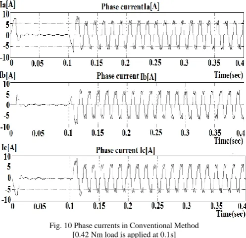
Fig. 10 Phase currents in Conventional Method [0.42 Nm load is applied at 0.1s]
The Fig. 10 shows the three phase current waveforms of conventional BLDC motor technique using PI controller. Initially the starting current of the motor is very high. Here the load of 0.42 Nm is applied at 0.1 s, so up to 0.1 s the stator current is low and after 0.1 s there is a sudden rise in current.
The simulink block of BLDC drive with four switch control technique is shown in Fig. 11, it consists of DC source, three phase inverter and current measurement. The set speed and actual speed is compared and error signal is send to PI controller and reference torque is proportional to the error signal.
The Fig. 12 shows the three phase current waveforms of proposed four switch BLDC motor technique.
Fig. 12 Phase currents in Proposed Method [0.47 Nm load is applied at 0.1s]
Initially the starting current of the motor is very high. Here the load of 0.47 Nm is applied at 0.1 s, so up to 0.1 s the stator current is low and after 0.1 s there is a sudden rise in current.
Fig. 13 Electromagnetic Torque in Conventional Method [0.47 Nm load is applied at 0.1 s]
Fig. 15 Motor speed in Conventional Method [0.47 Nm load is applied at 0.1 s]
Fig. 16 Motor speed in proposed Method [0.47 Nm load is applied at 0.1 s]
The speed and torque characteristics for conventional control technique are shown in Fig. 13 and Fig. 15 and the load is applied for 0.1 s. The speed and torque characteristic for developed four switch control technique are shown in Fig. 14 and Fig. 16 and the load is applied for 0.1 s.
IV. PERFORMANCE COMPARISON
In order to verify the developed four-switch converter system, a computer simulation has been performed with the conventional six-switch converter. As shown in Fig. 11, the 120 conducting quasi square shaped current profiles are successfully obtained using the developed direct current controlled pwm scheme, which are comparative with the ones of six-switch converter.
A prototype drive was designed and developed for the motor given in the appendix.
V. CONCLUSION
The four switch three phase inverter is developed and PI controller is implemented to achieve performance improvement and simulated using MATLAB and the results have been demonstrated. The simulated results of four switch three phase BLDC motor drive have shown the improved performance with the PI controller and hence it can be effectively used in replacement of six switch three phase BLDC motor drive. The proposed control scheme is efficient and robust, and easy to implement. The hardware implementation of the proposed system needs to be done to validate the capability of the conventional controller to cope up with speed and other parameter variations.
APPENDIX
BLDC MOTOR SPECIFICATIONS
Rated current 5 A Rated voltage 36 V Per phase Resistance (R) 0.57 ohms Inductance 1.5mH Moment of inertia (J) 23e-6kg-m^2 Rated Torque (T) 0.42N.m Torque constant 0.082N.m/A
REFERENCES
[1] Frede Blaabjerg, Dorin O. Neacsu and John K. Pedersen, “Adaptive SVM to Compensate DC-Link Voltage Ripple for Four-Switch Three-Phase Voltage-Source Inverters” IEEE Transaction Power Electronics, vol. 14, no. 4, July. 1999, pp. 743–752.
[2] Hendershot .J. R. and Miller T. J. E, “Design of Brushless Permanent-Magnet Motors”. Oxford, UK: Oxford Science, 1994.
[3] Lee .K.-W, Kim. D.-K, Kim .B.-T and Kwon. B.-I, “A novel starting method of the surface permanent-magnet BLDC motors without position sensor for reciprocating compressor,” IEEE Transaction Industrial Application, vol. 44, no. 1, Jan./Feb. 2008,pp. 85–92.
[4] Lee .B.-K, Kim .T.-H, and Ehsani .M, “On the feasibility of four-switch three-phase BLDC motor drives for low cost commercial applications: Topology and control,” IEEE Transaction Power Electronics, vol. 18, no. 1, Jan. 2003, pp. 164–172.
[5] Lin .C.-T, Hung .C.-W, and Liu .C.-W, “Position sensorless control for four-switch three-phase brushless DC motor drives,” IEEE Transaction PowerElectronics, vol. 23, no. 1, pp. 438–444, Jan. 2008.
[6] Niasar .A. H, Moghbeli .H, and Vahedi .A, “A novel sensorless control method for four-switch brushless DC motor drive without using any 30◦ phase shifter,” in Proc. IEEE Electrical Machines System Conference, 2007, pp. 408–413.
[7] Niassar .A. H, Vahedi .A, and Moghbelli .H, “Analysis and control of commutation torque ripple in four-switch three-phase brushless DC motor drive,” in Proc. IEEE Industrial Technology Conference, 2006, pp. 239–246.


![Fig. 12 Phase currents in Proposed Method [0.47 Nm load is applied at 0.1s]](https://thumb-us.123doks.com/thumbv2/123dok_us/1696051.1214771/9.595.171.423.537.670/fig-phase-currents-proposed-method-nm-load-applied.webp)
![Fig. 15 Motor speed in Conventional Method [0.47 Nm load is applied at 0.1 s]](https://thumb-us.123doks.com/thumbv2/123dok_us/1696051.1214771/10.595.173.426.178.451/fig-motor-speed-conventional-method-nm-load-applied.webp)