CONTAINMENT. DOME DELAMINATION
Prabir C. Basu
Civil & Structural Engineering Division, Atomic Energy Regulatory Board, Mumbai, India Vijay N. Gupchup
Formerly Pro-Vice Chancellor, University of Mumbai and Principal & Secretary VJTI, Mumbai, India
L. R. Bishnoi
Civil & Structural Engineering Division, Atomic Energy Regulatory Board, Mumbai, India.
ABSTRACT
The reactor buildings of Kaiga Atomic Power Project, Unit-l&2 have double containment structural system with an annular gap of 2.0 m. The Inner containment structure was made of prestressed concrete. Delamination of the inner containment dome took place during construction, after stressing of 66 cables out of a total of 183 cables in the dome was completed. The under surface of the dome delaminated in the central region and collapsed. The containment dome delamination was investigated in detail. Structural analyses were carried out with the objective of examining the delamination phenomenon. For the assessment of materials used in construction, samples collected from the debris at site were tested. The results of the material tests and the structural analyses were examined to establish the delamination mechanism, to explain the sequence of events and to identify the causes of delamination. The present paper contains a description of the occurrence of delamination; observations made from the inspection of failure site and investigation work.
INTRODUCTION
Delamination of inner containment (IC) dome of the Kaiga Atomic Power Project, Unit-1 (Kaiga-1) took place on 13 th May 1994 during the time of construction [1], and under surface of the dome failed and collapsed after delamination.
The reactor building of Kaiga-1 has full double containment with an annular gap of 2.0m between inner (primary) and outer (secondary) containment structures, (fig. 1). Both the containment structures and the internal struc~tre are supported on a common reinforce~ concrete raft. The inner containment (IC) structure is a prestressed concrete cylindrical wall of 42.56 m diameter and 610 mm thickness capped with a dome having structural configuration of prestressed concrete segmented hemispherical shell of 340mm general thickness. The special feature of this containment dome is that it has four large circular openings of 4.1m diameter, each for facilitating erection of steam generators (SG), and are designated as SG openings. There is a ring beam of depth more than 4.0m at the springing level of the dome joining it with the cylindrical inner containment wall (ICW).
The concrete used in the construction of the containment dome was M45 grade. Post tensioned prestressing system was adopted with 19K13 cables located inside 90mm diameter cable sheaths. A total of 558 cables were used in the entire containment system. The passive reinforcements were placed in an orthogonal grid in the central region and circumferential grid in the remaining portion with overlap between the two grids lying near the construction joints of pours 4 and 5 (A and B). Transverse (radial) reinforcement, connecting the top and bottom layers of reinforcement in the dome and crossties in the ring beam had not been provided. The IC dome and ring beam were cast in 4 and 3 numbers of pours respectively confined by 8 construction joints out of which 6 are in the dome and two are ion the ring beam.
The containment delamination was investigated in detail. The present paper deals with description of the occurrence of delamination, observations made from the inspection of failure site and investigation work. The paper also contains the results of the material tests and the structural analyses. These results were examined to establish the delamination mechanism and reasons for collapse.
OCCURRENCE OF CONTAINMENT DOME DELAMINATION
Delamination of the containment dome and subsequent failure of the under surface occurred on 13.05.1994 atter the stressing of 66 prestressing cables out of 183 traversing through the dome. After completion of concreting of the dome, followed by removal of shuttering planks during the period from 23.02.1994 to 23.03.1994, prestressing of the cables was commenced on 11.04.1994. Fixing of props, for supporting the shuttering for OC dome, on the outer surface of the IC dome
SMiRT 16, Washington DC, August 2001 Paper # 1557
was in progress. Based on the observations made at the failure site and the information obtained the following sequence of happenings on 13.05.1994 has been reconstructed [ 1 ].
1) Stressing of the 66 th cable was completed in the morning hours at about 4.0 A.M.
2) Dismantling and removal activities of structural steel pieces of one leg of central supporting derrick started at about 8.30 A.M. and was completed at about 10.30 A.M. Subsequently preparation for the removal of the other leg piece was started. Removal/lowering of the structural steel materials of shuttering formwork and those of the central derrick leg was being carried out simultaneously.
3) Following is the description of events, as experienced by the persons working inside the reactor building, when the first fall of debris occurred at about 11.0 A.M.,
i) Small pieces fell at the beginning of the incident.
ii) Loud sounds and noises were heard for about 7 to 8 minutes. iii) Inside of the reactor building was full of dust causing poor visibility. Further fall of debris occurred at about 12.30 hrs.
4)
O b s e r v a t i o n s M a d e f r o m the Site o f C o n t a i n m e n t D o m e D e l a m i n a t i o n
The under surface of the dome in the central portion got delaminated and fell completely. The upper portion stood in position under the action of its self-weight and whatever super imposed load it had on it. The failure surface was mapped using theodolite and plotted as shown in fig.2. Major observations made from the site of failure are,
i) Failure plane, in general, separated the concrete surface into two layers through the mid surface of the dome except in the deep bands of delamination. A close examination of the failure plane revealed a fairly smooth separation surface having indentation of reinforcement, cable sheaths and metal sheet (MS) water stops. The spread of delamination appeared to have regular shape. The extent of delamination and variation of its depth was symmetrical about the central line (grid -3) of the dome.
ii) Average depth of delamination was 170 mm, varying from 240 mm to 0 mm with a number of deep bands. These bands are marked as Band A (thickness: 210 mm to 240 mm) and Band C (thickness: 150 mm to 180 mm) in fig.2. In addition there were pockets of deep delamination of depth 190 mm to 210 mm marked as "B".
iii) At many places, where the reinforcement mesh was exposed or hanging, heavy congestion of reinforcement and evidence of non free-flow of concrete through the thickness of the shell indicated by voids, honey combing, etc. could be seen. In the fallen concrete debris, small voids/holes were noted, concentration of these voids being around the impression of sheaths. In a few locations hollow portions were observed below reinforcement bars. No transverse reinforcement (in radial direction) between the various layers of reinforcement bars and cable sheaths were seen.
In addition, the embedded parts around all the four SG openings were distorted and their anchorage with concrete was lost. Cable sheaths were found very near to the reinforcement in the lower level in some locations. A number of cracks were observed on the ring beam, major cracks being in the areas adjacent to some anchorage pockets. Grout tube units were found in a number of pockets of cable anchors. Telltale marks of grout and post construction repair work were visible on the inner surface of concrete of the western side of second circumferential joint.
Examination of the detailed design revealed that prestressing cables were placed at close spacing in certain zones, minimum distance being 108mm c/c. Reinforcements were also positioned too closely. Together, these had seemed to result in three sets of close meshes across the thickness of the dome (ref. fig.3).
- Top mesh consisting of the untensioned reinforcement at outer surface of the dome. - Middle mesh of prestressing cable sheaths.
- Bottom mesh consisting of untensioned reinforcement at inner surface of the dome.
The vertical gap between the mesh formed by cable sheaths and the top and bottom reinforcement mesh respectively, at regions where shell thickness is 340 mm, was only about 12 mm. The clear gaps between horizontal bars were also small. These gaps were further infringed upon by the double layer MS water stops, the construction joints, lapping and anchorage of reinforcements. Similar condition prevailed in the transition zones of dome thickness around SG opening, where reinforcement of orthogonal grid overlapped that of the circumferential-meridional grid. All these contributed to very high congestion. The situation was further worsened around SG openings due to the presence of loop cables, additional trimmer bars and embedded parts with anchoring lugs.
E X A M I N A T I O N OF D E L A M I N A T I O N P H E N O M E N O N
.\
\
Z
j,
L
+e+
+
.
¢4--+
0
+1,-i
~J
o
c~
C~
+~~
~i
~
+~j
~J
+~
c~
c~
cl~
c
+L
with this occurrence; first was the delamination of the dome, i.e. separation of the under surface from the top surface, and the second was collapse of the separated under surface.
Delamination is the splitting of a section into layers parallel to the mid plane, due to laminar cracking. Laminar cracking takes place under the action of direct tensile stress acting normal to the plane of cracking, or in plane almost parallel to the direction of compressive force. For cracking of a section, crack should first be initiated and then propagated. Crack initiation takes place when the induced stress at any point of a section, generally adjacent to a "flaw" in the material, crosses the limiting or critical stress of crack initiation (6oi). Crack propagation occurs ff the inducexi stress at the crack tip is more than the value of critical stress of crack propagation (c%).
Delamination of a prestressed concrete dome could be of single layer type or multilayer type. When curved cables of a prestressed concrete dome are stressed, membrane stresses are generated and the radial force generated given rise to radial stresses. Delamination of the dome could occur either when such induced stresses in the dome under the action of radial and/or membrane stress are more than cy~i and cy~p even though the characteristic compressive strength of concrete is adequate. Or, despite induced stresses being within theoretically calculated values of 6ci and 6~, the quality of in-situ concrete is poor resulting in lower capacity of the structure for withstanding induced stresses and also lower crack resistance capability. Combination of the above two can also cause delamination. Important stress parameters for examination of delamination phenomena are induced stresses (membrane and radial), 6oi and 6~p. Mohr's failure criteria [4] was used to derive cry, and is given by the following expression in case of negligible transverse shear stress,
~ = ft~ (1-~Jf~) (1)
Where, 6o is induced compressive stress; ft~ and f~ are limiting values of the tensile and compressive stresses respectively of the in situ concrete. In case of tri-axial state of stress, ~c is the maximum principal compressive stress, which could be calculated from the hi-axial membrane stresses ~x and ~y.
Concrete, passive reinforcement and prestressing cables were tested collecting samples from the debris. The test results helped to ascertain whether the materials of requisite quality had been used in constn~'tion and to estimate f~, ft~, c~ci and ~q, of the dome concrete. Structural analyses were carried out to determine the state of induced stresses, a~ and ~t, in the as-built dome at the time of delamination.
Materials
Testing
A number of tests on materials were camed out on samples collected from the fallen debris at failure site and also from the in-situ concrete of the remaining intact portion of the dome. Petrographic analysis, chemical analysis, analysis for assessment of mix proportion, tests for compressive strength and sprit tensile strength were carried out for concrete. Cores for the tests were collectext from the concrete lumps. Further, the quality of test samples was checked by USPV tests. The test result assured that concrete of the test samples was of good quality. High tensile steel strands of prestressing cables and high strength deformed bars of passive reinforcement were tested for strength. Tests on chemical admixtures were also carried out. All test results indicated that the materials were of acceptable quality. Apprehension about the bond strength (pull out) of dome concrete arising out of the observation regarding clear indentation of reinforcement, cable sheath and MS water stop on the delaminated surface of concrete was investigated e ~ m e n t a l l y [6]. These indentations were not due to the weakness of concrete in bond strength but due to the effect of split tension.
The density, modulus of elasticity and characteristic value of in-situ compressive strength (fck) of concrete were estimated as 254.842 kg/m 3, 3.823x10⁹ k ~ m 2 and 44.11 MPa respectively, the latter being very close to the design concrete grade M45. Split tensile strength was found to be 3.37 MPa which was also in the acceptable range. Values of ft~ and f~ of equation (1) correspond to the in-situ material properties of concrete. The in-situ compressive strength ( c t ~ ) of dome concrete was estimated as 29.5 MPa [5]. Range of direct tensile strength of in-situ concrete was estimated as 60% to 75% of the split tensile strength of 3.37 MPa i.e. 1.9 MPa to 2.5 MPa. The most reasonable value appeared to be 2.08 MPa which was based on the mean direct tensile strength, calculated using fck (cube) value determined from core test results and applying formulae of CEB-FIP model code [7]. Probable range of fracture energy Gf, for the concrete around the mid depth of dome was estimated to be in the range of 10.5 N/m and 30.5 N/m. Most probable value would be around 24.5 N/m, which was derived by Gellue for concrete corresponding tensile strength 2.015 MPa [8]. Corresponding estimated range of ~ v was 1.44 to 2.61 MPa [9].
Structural
analysis
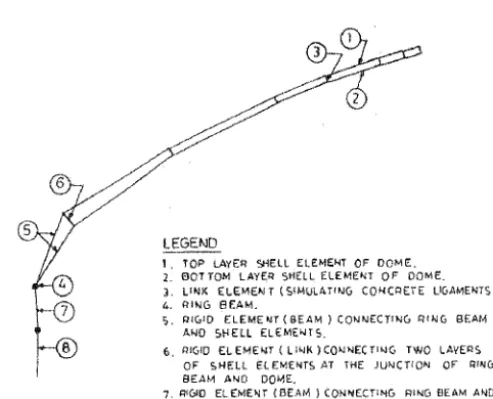
shell elements and considering entire thickness as solid made of concrete only. In Model-2, overall 340 mm thickness of concrete shell was considered to be consisting of two 80 mm thick reinforced concrete layers at top and at bottom each, interconnected only by 180 mm long concrete ligaments located in the space between the cable sheaths. Ligaments were simulated in the model as link elements. Finite element meshes of configuration similar to that of Model-1 were used for top and bottom layers. The containment wall was also descretised in the same pattern as that in Model-1.
Material properties as determined from the test results of samples collected from debris were used along with Poisson's ratio = 0.2 in the analyses. The loads, prevailing prior to delamination were considered in the analysis. These were self-weight; construction load and prestressing load. In calculating the self-weight of the dome, reduction on account of the hollows due to cable sheaths was considered. Under the category of construction load, weight of props, fixed on the outer surface of IC dome to support shuttering for OC dome concreting, was considered.
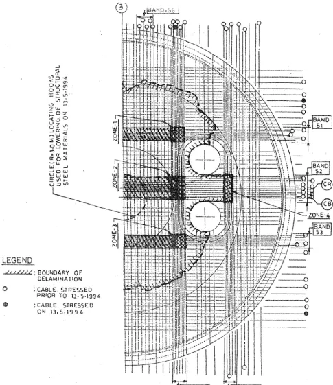
About 30 analysis cases were considered to determine the state of stresses in the dome in the region where delamination occurred, to conduct parametric studies and to examine the sensitivity of the model for assessing the accuracy of the results within the scope of the analysis. It was observed that both the radial stress and membrane stresses at the region where delamination took place were insensitive to the modeling and other u n ~ i n t i e s associated with dome-ring beam junction, ring beam, ring beam-wall junction, walls, etc. Structural analysis results were examined vis-$-vis information related to design and construction activities prior to delamination and material properties. Mapping of delamination area was superimposed on the cable layout for this purpose, fig.6. Status of cable stressing prior to delamination, position of construction joints and location of hooks used for lowering the dismantled parts of central derrick are indicated in this figure. Compressive stresses induced were within the values for in-situ compressive strength of the dome concrete i.e. 29.5 MPa except at two locations where they exceeded marginally. It was seen from the analysis of results of Model-2 (ref. Table-1) that the induced radial tensile stresses at a number of locations were in the range of limiting tensile stress for crack initiation and also critical stress for crack propagation and beyond these ranges at some locations. Important observation made from the structural analysis work was that magnitude of radial tension in the transition zone of the dome thickness (from normal thickness to higher thickness around the SG openings) is very sensitive to the slope of the surface. Magnitude of radial tension increases with increase in the slope.
The state of stress of the affected area of the as-built dome was determined using the methodology of reference-10. Both membrane and radial stresses are computed using one model [10]. State of stress, variation of radial stresses and deflected shape determined from this analysis were found to be similar to that obtained from results computed with Models 1 and 2. Membrane compressive stress normal to ungrouted cable sheath would induce stress concentration in the radial direction around the opening of the sheath. It was observed that the stress concentration was very high in zones-1, 2 and 3. Such stress concentration indicated the potential of crack initiation; it died down within a short distance [11].
Prior to collapse of under surface of the dome, activities related to dismantling and removal/lowering of s t r u ~ r a l steel members of the central derrick using hooks embedded in concrete were in progress. The maximum probable value of the radial tension induced by the hooks in the dome during the above removal/lowering operation of structural steel members was estimated to be 0.24 MPa [9]. Total radial tension combining the effect of hook and that due to stressing of cables in the region of the hooks worked out to be 0.45 MPa; thus the hook load could not have initiated laminar cracking in the dome.
Probable failure modes for collapse of the undersurface could be buckling, crushing and bending. All the three possible modes were examined in detail and failure due to bending appeared to be highly probable [9]. Subsequent to laminar cracking, the separated bottom layer of the band resisted the loading due to radial pressure exerted by the stressed cables. The magnitude of loading on these bands was different for different segments depending on which cable had been stressed. Under the action of such loading, bending moment was induce~ on the strip of the bottom layer (at critical zones) having span equal to the width of the band. The magnitudes of the bending moments at various segments along with the moment of resistance of the bottom strips in the respective bands are given in Table-2. The moment of resistance was calculated using IS456 method [5] without considering partial factor of safety. Inducexl bending moment at zones - 1, 2 and 3 were higher than the corresponding moment of resistance in all the cases; moment of resistance being governed by compression failure. In case of band $2, moment of resistance was lower than all values of bending moment.
Observation Made from Structural Analysis
CONCLUSION
The induced radial tension coupled with the effect of membrane compression, was higher than the tensile load carrying capability of the Kaiga-1 IC dome in radial direction. The delamination originated at the intersections of bands of closely spaced cables located around the thickened portion around SG opening. The depth of delamination at this location is the maximum. It has also been revealed from the structural analyses that around this location, values of radial tensile stresses were maximum. The delamination, once originated at this location, progressively propagated towards the crown. Loading of hooks, fixed on the bottom surface of the dome during removal/lowering of the structural steel members of central derrick, did not have material impact directly or indirectly on the initiation of the delamination.
The collapse of under surface of the dome occurred due to the combined effect of progressive extension of lamination cracking and failure of the laminated bottom surface under the action of bending moment induced by the radial component of prestressing force.
TABLE-l: SUMMARY OF STATES OF STRESS IN THE CONTAINMENT DOME
Zone Location Intersection-n
of closely
spaced cable bands Deep delami- nation bands Induced membrane stressStresses in as-built dome (MPa)
Induced radial stress
Case-1 Case-2 Case-3
Critical stress cr~i Radial stress (MPa) Case-4
1 $1 - $4 C 13.40 1.470 1.463 2.729 1.04- 1.37 1.44-2.61 0.85
2 S : - $4 A & B 11.39 2.27 2.578 3.319 1.17-1.63 1.44-2.61 1.83
. . . . . .
3 $3 - $4 C 11.88 1.256 1.249 2.60 1.14-1.49 1.44-2.61 0.81
4 S: - Ss - 7.57 2.68 2.934 4.169 1.41-1.86 1.44-2.61 2.3
Note:
Case-1: Prestressing load for all cable stressed prior to delamination in one step. Case-2: Structural analysis for radial stress carried out in three steps,
Step-1 Prestressing force for cables stressed up to 11.5.1994.
Step-2 Link elements in which induced radial stress, in step-1 analysis, was more than cr~ were removed and modified structure was analyzed with prestressing force for cable stressed up to 12.5.1994. Step-3 The structure was further modified by removing the links in which induced radial stress, in step-2
analysis, was higher than cr~ and analyzed for prestressing force for cables stressed up to 13.5.1994. Case-3 Prestressing load for full design value of cables.
Case-4 Prestressing load for full design value of cables with increased value of minimum cable spacing (270 mm) and increased thickness (450 mm).
Band #)
$1
$2
$3
TABLE 2: BENDING MOMENT IN BOTTOM STRIPS OF DEEP DELAMINATED BANDS
Depth
190 ... 150 210 190 190 150Estimated bending moment in band segment
p1 (2) 5.85 5.83 23.95 23.92 4.o9
(x
104NM)
e/2)
11.79 11.70 40.95 40.99 . . . 9.56 9.47 p3(2) 11.75 18.08 57.90 58.65 15.66 15.96 4.07Moment o f resistance (xlO4Nm) 10.67 7.54 12.23 10.67 10.67 7.54
Note: 1. For reference to bands see figure 6.
ACKNOWLEDGEMENT
Authors gratefully acknowledge contribution of Professor P. Dayaratnam, Vice-Chancellor (retd.), Jawharlal Nehru Technical University, Hyderabad; Mr. N. V. Merani, Principal Secretary (retd.), Govt. of Maharastra; Mr. V. Krishnamurthy, retd. Chief Engineer (Civil), IGCAR, Kalpakkam; Professor N. Rajagopalan, Department of Civil Engineering, liT, Madras, Chennai; Dr. C. S. Viswanatha, Chief Consulting Engineer, Torsteel Research foundation in India, Bangalore; and Dr. V. Venkat Raj, Director, Health & Safety group, BARC, Mumbai in the investigation work. Sincere thanks are also due to Atomic Energy Regulatory Board for permission to publish the paper.
R E F E R E N C E
° . °
5.
° .
8.
°
10.
11.
... , "Final Report on the Investigation of Inner Containment Dome, Kaiga Project, Unit-l", Expert Committee to Investigate Kaiga Dome Failure, 22 "a April 1995, Atomic Energy Regulatory Board, Mumbai, India.
... , "Containment Dome Report: Turkey Point Unit-3", NRC PDR Docket No. 50-250, Florida Power and Light Company, Mia.m.i, December 23, 1970.
Moreadith Fredrik L, Pages Richard E, "Delaminated Prestressed Concrete Dome: Invesitgation and Repair", ASCE Journal of Structural Engineering, Vol. 109, No.5, May 1983.
Timoshenko SP, Goodier JN, "Theory of Elasticity", Third Edition, 1970, McGraw- Hill Book Company, New York. ... , "indian Standard Code of Practice for Plain and Reinforced Concrete", 3 rd revision, IS456-1978, Bureau of Indian Standard, New Delhi-india.
Basu Prabir C., Rajgopalan N., "Behaviour of Concrete with Reinforcement under Split Tension", Transaction of the SMiRT- 14, Lyon, France, August 17-22, 19997.
"CEB-FIP Model Code", CEB-FIP, 1990.
Shah SP, Ahmed SI-Lh, "High Performance Concrete", Edward A r m o l d - Member of the Holder Headline Group, YNBZYA, 1994, ISB No. 3 4 0 - 58922-1.
... , "Analysis for Failure of lC Dome, Reactor Building, Kaiga Project, Unit-l", Task Force No. TF3, Expert Committee to Investigate Kaiga Dome Failure, Report No. AERB/199/KI-TF3/2, April 1995, Atomic Energy Regulatory Board, Mumbai, India.
Buragohain D N, Mukherjee A, "PARCS - A Prestressed Concrete and Reinforced Concrete Shell dements for Analysis of Containment Structures", Transaction of 12 th International Conference on Structural Mechanics in Reactor Technology (SMiRT-12), August 120, 1993 Stuttgart, Germany.
... , "Review of the Design of Inner Containment Structure of Reactor Building-l", Kaiga Atomic Power Project, Report No. Kaiga- 1/21000/7016/A, Vol. I-V, October 1994, Development Consultants Ltd., Calcutta, India.
t~,G ~BEAt4
6 mOlD ELEIqEHT ( LZ~qK )CO~ECTI~G TWO LAYE~qS I OF SHELL E L E M E N T S AT THE JUNCTION O F ~ING
BEA,',,,i A N D DOME.
7. RiGiD ELEMENT (BEAM) CONNECTZNG RiNG BEAM A N D
INKIER CONTA1NWENT WALL ( ~C W).
8. SHELL ELEMENT OF INKIER CO~,ITAINMENT WALL(ICW ).
Fig. 5 Finite element model 0fKaiga-1 Dome (Model,2)
iB,AI~U~SS~
j
~ , - ,
~ . ~,~
uJ ~
~ Q w
u w .1~
LEGEND
: B O U N D A R Y OF
DELAMINATION
O " CABLE. STRESSED
PRIOR TO 13,, 5 , i 9 9 4
@ : C A B L E STRESSED
ON 1 3 , 5 , t 9 9 z~
N t
LU
Z.
Q
U
il
\ ®
0
... ~ - 0
ZONE~4
BAND ~S BAND $ 5