THIAN LEE ENG
THIAN LEE ENG
A thesis submitted in fulfilment of the requirements for the award of the degree of
Master of Science (Physics)
Faculty of Science U
niversiti Teknologi Malaysia
ACKNOWLEDGEMENTS
ABSTRACT
ABSTRAK
TABLE OF CONTENTS
CHAPTER TITLE PAGE
TITLE i
DECLARATION ii
DEDICATION iii
ACKNOWLEDGEMENT iv
ABSTRACT v
ABSTRAK vi
TABLE OF CONTENTS vii
LIST OF TABLES xi
LIST OF FIGURES xii
LIST OF SYMBOLS xvii
LIST OF APPENDICES xix
1 INTRODUCTION 1.1 Light Modulation 1
1.2 The History Of Electro-optic 2
1.3 Research Background 3
1.4 Comparison Between Different Techniques Of Beam Modulation 6
1.5 Research Objectives 8
1.6 Scopes Of Research 8
2 THEORY
2.1 Introduction 10
2.2 Polarization 10
2.3 Malus’ Law 12
2.4 Birefringence (Double Refraction) 14 2.5 Analysis Of Elliptically Polarized Light 15 2.6 Optics Of Uniaxial Crystal 16 2.7 The Pockels (Linear Electro-optic) Effect 18
3 METHODOLOGY
3.1 Introduction 21
3.2 BPX65 Photodetector 22
3.3 Equipments 23
3.3.1 Helium-Neon (He-Ne) Laser 24 3.3.2 Polarizer and Analyzer 25
3.3.3 Quartz Crystal 26
3.3.4 Calcite Crystal 27
3.3.5 Lithium Niobate Crystal (LiNbO3) 28
3.3.6 Pockels Cell 29
3.3.7 TDS 210 Digitizing Real-Time Oscilloscope 30 3.3.8 Long Scale Galvanometer And Photoelectric
Detector 31
3.3.9 High Voltage Probe 33 3.4 Demonstration Of The Birefringence Phenomenon 34
4 DEVELOPMENT OF PULSE GENERATORS
4.1 Introduction 38
4.2 Electro-optic Driver 39
4.3 CD4528BCN Dual Monostable Multivibrator 39
4.4.1 Repetitive Mode With Frequency Range Less
Than 300 Hz 42
4.4.2 Single Pulse 44
4.4.3 Repetitive Mode With Frequency Of 1 Hz 46
4.5 Calibration Of Pulse Generators 50
4.6 Triggering Of An Electro-optic Driver 56
4.7 Summary 59
5 DETERMINATION OF THE POLARIZATION STATE OF HE-NE LIGHT OUT OF NATURAL BIREFRINGENT MATERIALS 5.1 Introduction 60
5.2 Polarization State Of He-Ne Light 61
5.3 Polarization State Of He-Ne Light Out Of Quartz Crystal 65
5.4 Polarization State Of He-Ne Light Out Of Calcite Crystal 71
5.5 Summary 76
6 DEVELOPMENT OF TRANSVERSE POCKELS CELL 6.1 Introduction 77
6.2 Designing Of Pockels Cell House 78
6.3 Fabrication Of Transverse Pockels Cell 78
6.4 Electrifying The Transverse Pockels Cell 79
6.5 Experiment Of He-Ne Polarization By Using Pockels Cell 80
6.6 Characterization Of He-Ne Polarization State Through Transverse Pockels Cell 83
6.8 Comparison Between The Output Intensity Of The
Commercial and Transverse Pockels Cell 99
6.9 Summary 101
7 OPTICAL SWITCH
7.1 Introduction 102
7.2 Optical Switching Operation 102 7.3 He-Ne Switching By Using Transverse
Pockels Cell 105
7.4 He-Ne Switching By Using Commercial
Pockels Cell 109
7.5 Comparison Between The Switching of He-Ne By Using The Transverse Pockels Cell And The
Commercial Pockels Cell 111
7.6 Summary 113
8 CONCLUSIONS AND SUGGESTIONS
8.1 Conclusion 114
8.2 Problems 116
8.3 Suggestions 117
REFERENCES 118
APPENDICES A – O 124-140
LIST OF TABLES
TABLE NO. TITLE PAGE
1.1 Comparison between different modulation techniques 7 2.1 Some negative and positive uniaxial crystals 18 4.1 The truth table of CD4528BCN dual monostable multivibrator 48 4.2 Calibration result obtained from various pulse generators 56 5.1 Data obtained from the experiment of the He-Ne light
polarization 63
5.2 Polarization of He-Ne light out of Q 67
5.3 Polarization state of He-Ne out of calcite 73 6.1 Determination of He-Ne polarization state out of the
transverse Pockels cell 90
6.2 Determination of He-Ne polarization state out of the commercial
Pockels cell 99
LIST OF FIGURES
FIGURE NO. TITLE PAGE
1.1 Lumped modulator and its electric circuit 4
1.2 Traveling-wave modulator using two-plate structure 4
1.3 Zigzag modulator 5
1.4 Optical waveguide modulator 5
2.1 An electromagnetic wave 11
2.2 Light wave passing through a polarizer 11
2.3 Resolution of the amplitude of the transmitted light, Ao
into two components, A1 and A2 13
2.4 The crystal resolves polarized light into ordinary, O
and extraordinary, EObeams 14
2.5 Resolution of the amplitude of transmitted polarized light
into two components, a and b 16
2.6 Principal plane of the crystal (kz) and (a) ordinary beam and
(b) extraordinary beams 17
2.7 Transverse Pockels effect 19
2.8 Longitudinal Pockels effect 20
3.1 Schematic diagram of BPX65 photodetector 22 3.2 Typical spectral response of BPX65 photodiode 23
3.3 He-Ne laser with 1 mW output power 24
3.5 Polarizer 26
3.6 Quartz crystal 27
3.7 Calcite crystal 28
3.8 Cubic lithium niobate crystal 29
3.9 Laser light enters a Pockels cell through the window beside
the insulator housing 30
3.10 LT PYRKAL CJSC Pockels cell 30
3.11 TDS 210 Digitizing Real Time Oscilloscope 31
3.12 Schematic diagram of detector system 32
3.13 Long scale galvanometer 32
3.14 Photoelectric detector 33
3.15 Tektronix high voltage probe 34
3.16 Demonstration setup of birefringence 35
3.17 Ordinary, O and extraordinary, EO beams out of the calcite. (a) The existence of the two He-Ne beams out of calcite and
(b) The two projected beams of He-Ne 36 3.18 Occurrence of double images of object when viewed through
the calcite 37
4.1 Electro-optic driver 39
4.2 Schematic diagram of CD4528BCN dual monostable
multivibrator 40
4.3 CD4528BCN dual monostable multivibrator 41 4.4 Schematic diagram of the pulse generator (f < 300 Hz) 42 4.5 The whole block circuit diagram of the pulse generator
(f < 300 Hz) 43
4.6 Schematic diagram of single pulse generator 45 4.7 The block circuit diagram of single pulse generator 45 4.8 Schematic diagram of the pulse generator with frequency of
1 Hz 47
4.9 The block diagram of the pulse generator with the frequency
4.10 The oscillograms of the input at label of (a) A, (b) B, (c) Clear and
the output (d) Qof Figure 4.9 49
4.11 The circuit of 1 Hz pulse generator mounted in a black
plastic box 50
4.12 (a) Frequency versus resistance graph and
(b) Frequency versus 1/R graph for pulse generator with
f < 300 Hz (Vin = 10V and 12V) 51
4.13 (a) Frequency versus resistance graph and (b) Frequency versus 1/R graph
for pulse generator with 1 Hz (Vin = 10V and 12V) 52
4.14 Pulse width versus resistance graph for pulse generator
with f < 300 Hz 54
4.15 Pulse width versus resistance graph for the single pulse generator 54 4.16 Pulse width versus resistance graph for the pulse generator
(f = 1 Hz) 55
4.17 The output of the electro-optic driver when triggered by (a) pulse generator with frequency of 100 Hz, and
(b) single pulse generator 57
4.18 The pulse width of (a) 1Ps, (b) 2Ps, (c) 3Ps and (d) 4Ps
produced by the pulse generators 58
5.1 Schematic diagram of the experiment to determine the
polarization of He-Ne light 61
5.2 Experimental arrangement for measuring polarization state of
He-Ne laser 62
5.3 Current ratio, i/io versus cos2Tgraph 63
5.4 Schematic diagram of the experiment to determine the polarization state
of He-Ne out of quartz crystal, Q 65
5.5 Experiment setup for determination of the polarization state
of He-Ne out of quartz crystal, Q 66
5.8 Schematic diagram of the experiment to determine the
polarization state of He-Ne light out of calcite crystal 71 5.9 Experimental setup for the determination of the polarization state
of He-Ne light out of calcite 72
5.10 Current, i versus cos2T out of calcite graph 74
6.1 Fabricated Pockels cell house 78
6.2 The setup of the transverse Pockels cell 79
6.3 Ensemble of optical switch 80
6.4 Schematic diagram of the experiment by using fabricated
transverse Pockels cell 81
6.5 Experimental arrangement by using fabricated
transverse Pockels cell 82
6.6 Schematic diagram of the experiment by using commercial
Pockels cell 82
6.7 Experimental arrangement by using commercial Pockels cell 83 6.8 Graph of power, P versus T at 2 kV out of transverse Pockels
cell 84
6.9 Graph of power, P versus T at 3 kV out of transverse Pockels
cell 84
6.10 Graph of power, P versus T at 4 kV out of transverse Pockels
cell 85
Pockels cell 93 6.20 Graph of power, P versus T at 3 kV out of commercial
Pockels cell 93
6.21 Graph of power, P versus T at 4 kV out of commercial
Pockels cell 94
6.22 P versus T at f = 100 Hz (V = 2 kV, 3 kV and 4 kV) 95 6.23 P versus T at f = 200 Hz (V = 2 kV, 3 kV and 4 kV) 95 6.24 P versus cos2T at 2 kV (f = 100 Hz) 96 6.25 P versus cos2T at 2 kV (f = 200 Hz) 96 6.26 P versus cos2T at 3 kV (f = 100 Hz) 97 6.27 P versus cos2T at 3 kV (f = 200 Hz) 97 6.28 P versus cos2T at 4 kV (f = 100 Hz) 98 6.29 P versus cos2T at 4 kV (f = 200 Hz) 98 6.30 P versus T (f = 100 Hz and V = 4 kV) 100 7.1 Schematic diagram of light switching experiment by
using transverse Pockels cell 103
7.2 Light switching experiment by using transverse Pockels cell 103 7.3 Schematic diagram of light switching experiment by
using commercial Pockels cell 104
LIST OF SYMBOLS
a - Amplitude of the light component A1
Ao - Amplitude of the transmitted light
A1 - Amplitude of the light component
A2 - Amplitude of the light component
As - Total amplitude of the light
B - Pulse width
C - Capacitance
b - Amplitude of the light component A2
d - Width of the crystal
E - Electric vector
EO - Extraordinary beam
f - Frequency
F - Focal length
H - Magnetic vector
I - Intensity of the transmitted electromagnetic or mechanical waves I - Intensity of the He-Ne light
Io - Intensity of the incident light
i - Current
k - Multiple factor
k - Wave vector of the light wave KPD - Responsivity of the photodiode
l - Length of the crystal
no - Refraction index of the ordinary beam 'n - Birefringence or double refraction M - Slope of the graph
O - Ordinary beam
P - Light power
P1 - Polarizer
P2 - Analyzer
Q - Quartz crystal
r - Electro-optic coefficient
R - Resistance
t - Period
V - Applied voltage
Va - Average voltage
Vin - Supplied voltage
z - Optical axis
O - Wavelength of the light
T - Angle of the analyzer
LIST OF APPENDICES
APPENDIX NO TITLE PAGE
A Technical specifications of the electro-optic driver 124
B Optical properties of lithium niobate 125
C CD4528BCN Dual Monostable Multivibrator 126
D Data obtained from the experiment by using
transverse Pockels cell (f = 200 Hz and V = 2 kV) 129 E Data obtained from the experiment by using
transverse Pockels cell (f = 100 Hz and V = 2 kV) 130 F Data obtained from the experiment by using
transverse Pockels cell (f = 200 Hz and V = 3 kV) 131 G Data obtained from the experiment by using
transverse Pockels cell (f = 100 Hz and V = 3 kV) 132 H Data obtained from the experiment by using
transverse Pockels cell (f = 200 Hz and V = 4 kV) 133 I Data obtained from the experiment by using
transverse Pockels cell (f = 100 Hz and V = 4 kV) 134 J Data obtained from the experiment by using
commercial Pockels cell (f = 200 Hz and V = 2 kV) 135 K Data obtained from the experiment by using
commercial Pockels cell (f = 100 Hz and V = 2 kV) 136 L Data obtained from the experiment by using
M Data obtained from the experiment by using
commercial Pockels cell (f = 100 Hz and V = 3 kV) 138 N Data obtained from the experiment by using
commercial Pockels cell (f = 200 Hz and V = 4 kV) 139 O Data obtained from the experiment by using
INTRODUCTION
1.1 Light Modulation
Applications of laser light always require the modulation of some properties of the laser light wave. The modulation of light wave is to control variation of some detectable properties of the light wave, such as its intensity (amplitude), phase, wavelength (frequency) or polarization (direction of the beam propagation)
(Schawlow, 1969; Hammer, 1975). A modulator is a device that alters a detectable property of a light wave corresponding to an applied electric signal (Hammer, 1975).
laser-beam by using these effects is faster and more reliable than the mechanical methods. Among these three interactions, electro-optic effect has received most attention and is widely used for light modulation as it provides the fastest modulation (Schawlow, 1969; Booth and Hill, 1998). For electro-optic effect, the application of an electric field across certain crystal is used to result in change of refraction index of the crystal. The crystal becomes birefringent under the influence of the applied electric field (O’Konski, 1978; Noriah Bidin, 2003). These crystals include,
potassium dihydrogen phosphate (KDP), potassium dideuterium phosphate (KD*P), lithium niobate (LiNbO3), lithium tantalite (LiTaO3) and cesium dihydrogen arsenate
(CDA) (Kuhn, 1998).
The electro-optic effect can be used to control the intensity or phase of the propagating light (Yariv, 1997). The modulation by using electro-optic effect is the basic operation concept for the optical modulator, optical switch, Q-switch, and deflector (Zajac, 1982; Laud, 1985; Chuang, 1996).
1.2 The History Of Electro-optic
In 1875, Kerr observed that certain dielectric medium become doubly refractive when placed in a strong electric field (Schawlow, 1969; Kaminow, 1974). This effect was consequently named as Kerr effect, or quadratic electro-optic effect. He also discovered this effect in liquids such as carbon disulphide (Kaminow and Turner, 1966; Camatini, 1973; Kaminow, 1974). The Kerr effect can be observed in any crystal (Schawlow, 1969).
center of symmetry (Schawlow, 1969). During the nineteenth century, Pockels examined the Pockels effect in quartz, tourmaline, sodium chlorate and K-Na tartrate salt (Rochelle salt) (Kaminow and Turner, 1966).
1.3 Research Background
The first useful Pockels cell was made of potassium dihydrogen phosphate (KDP) by Billings in 1949. However, this device was not capable to be used for high-frequency operation. In 1961, Schawlow, developed a high frequency laser modulator made of KDP crystal based on the Pockels effect. But, the power required was too high for practical use. This stimulated interest of many researchers in
searching other feasible crystals (Kaminow, 1974).
Since then, lithium niobate (LiNbO3), lithium tantalite (LiTaO3) and
ammonium dihydrogen phosphate (ADP) are a few more capable materials used for light modulation (Schawlow, 1969). In 1967, Kaminow and his group constructed light intensity modulators by using LiTaO3and LiNbO3. The performance of the
LiNbO3 intensity modulator has of slight advantage compared to the LiTaO3due to
the larger electro-optic coefficient of LiNbO3. Light modulation by using Pockels
effect on LiNbO3, KDP and ADP was well established (White and Chin, 1972;
Salvestrini et al., 2004).
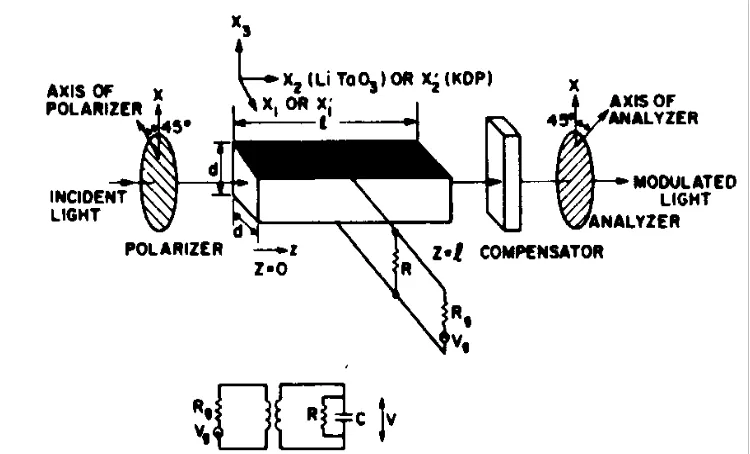
modulation of frequency < 1 GHz and with the crystal length about 1 cm. Traveling-wave and zigzag modulator are used for modulation of frequencies greater than 1 GHz (Denton et al, 1967). The type of modulator chosen depends on the required driving power and crystal length (Chen, 1970).
Figure 1.1: Lumped modulator and its electric circuit (Chen, 1970)
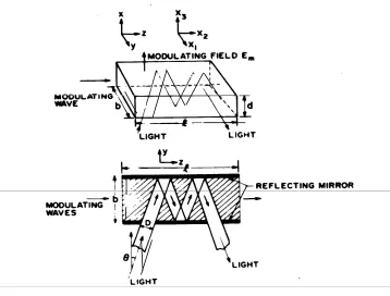
Figure 1.3: Zigzag modulator (Chen, 1970)
Figure 1.4: Optical waveguide modulator (Hammer, 1975)
A lumped electro-optic optical modulator has been developed by using single crystal LiTaO3which is in a cylinder form. A transistor driver-amplifier with a 0.2
W output power is used to drive the LiTaO3at a light wavelength of 632.8 nm In
The accurate and direct determination of the phase retardation due to the birefringence of certain materials can be done by using a technique based on the linear variation of the transmitted intensity with the applied electric field to an amplitude modulator (O’Shea, 1985).
1.4 Comparison Between Different Techniques Of Beam Modulation
Besides the Pockels (linear electro-optic) effect, other techniques like magneto-optic, acousto-optic and Kerr effects can also be used to change the refraction index of an optical medium through the application of an external field. However the Pockels (linear electro-optic) effect is chosen because of some
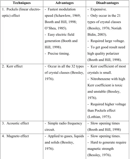
Table 1.1: Comparison between different modulation techniques
Techniques Advantages Disadvantages
1. Pockels (linear electro-optic) effect
- Fastest modulation speed (Schawlow, 1969; Booth and Hill, 1998; O’Shea, 1985). - Easy electric field generation (Booth and Hill, 1998).
- Precise timing.
- Expensive.
- Only occur in the 21 types of crystal classes (Bessley, 1976; Noriah Bidin, 2003).
- Required large voltage. - To get good result need high quality polarizer (Booth and Hill, 1998). 2. Kerr effect - Occur in all the 32 types
of crystal classes (Bessley, 1976).
- Kerr coefficient of most crystals is small.
- Nitrobenzene with high Kerr coefficient is toxic and unstable (Bessley, 1976).
- Required higher voltage than Pockels effect
(Lothian, 1975). 3. Acoustic effect - Simple radio frequency
circuit.
- Slow opening times (Booth and Hill, 1998) 4. Magneto effect - Applied to gases, liquids
and solids (Bessley, 1976).
- Slow opening times. - Hard to generate require magnetic strength
(Bessley, 1976).
In this project, Pockels effect has been applied to produce an optical switch. It is an important element in the construction of a Q-switched Nd:YAG laser for medical purpose.
1.5 Research Objectives
The objectives of this research are listed as followed:
1. To diagnose birefringence characteristic, 2. To design a trigger system,
3. To develop a Pockels cell and
4. To characterize the output of an optical switch.
1.6 Scopes of Research
In this research, the polarization of He-Ne light was analyzed by using
Malus’ Law. Natural birefringent materials, like quartz and calcite crystal were used as specimen.
A transverse Pockels cell was developed by applying electric field across the lithium niobate crystal. High voltage was supplied to Pockels cell. A pulse
1.7 Organization of Thesis
This thesis consists of seven chapters. The introduction, research
dimension and the material of the electrodes in the transverse Pockels cell were not suitable to produce a strong electric field to the crystal.
The CD4528BCN dual monostable multivibrator used was very sensitive. The operation of single and repetitive mode pulse generator could not be combined. Therefore, two types of pulse generator were developed.
8.3 Suggestions
The project should be continued for further studies by packaging or combining all the separate components like pulse generator, power supply, electro-optic driver and Pockels cell to become a complete optical switch system.
In order to use this system as a Q-switch system for high power laser, the Pockels cell should be provided with a temperature controller to avoid overheating, which will damage the crystal during switching.
It is also suggested that an interlocking system should be installed in this system to avoid any accident, by switching off the system immediately whenever overheating occurs.
REFERENCES
Andrews, C. L. (1960). Applications in Electromagnetic Spectrum. New Jersey: Prentice Hall PTR. 207-211.
Bessley, M. J. (1976). Lasers and Their Applications. London: Taylor & Francis Ltd. 71-95.
Billings. A (1993). Optics, Optoelectronics, and Photonics Engineering Principles and Applications. London: Prentice Hall. 110-132.
Booth, K. and Hill, S. (1998). The Essence of Optoelectronics. Singapore: Prentice Hall. 135-150.
Bozic, S. M. (1975). Electronic and Switching Circuits. London: Edward Arnold. 189-192.
Camatini, E (1973). Progress in Electro-optics. New York: Plenum Press. 1-10
Carr, J. J. (1999). Electronic Circuit Guide: Oscillator. New York: Prompt Publications.
Chuang, S. L. (1996). Physics of Optoelectronic Devices. New York: John Wiley & Sons, Inc. 508-509.
Clarke, D. and Grainger, J. F. (1971). Polarized Light and Optical Measurement. New York: Pergamow Press.
Denton, R. T., Chen, F. S. and Ballman, A. A. (1967). Lithium Tantalate Light Modulators. Applied Physics. Vol.38 (4): 1611-1617.
Dmitriev, V. G., Gurzadyan, G. G. and Nikogosyan, D. N. (1991). Handbook of Nonlinear Optical Crystals. New York: Springer-Verlag. 6-7.
Data Sheet of CD4528BM/CD4528BC Dual Monostable Multivibrator. National Semiconductor, Inc. (1988)
Duncan, T. (1985). Electronics for Today and Tommorrow. London: John Murray Ltd.
Enami, Y. (2003). Electro-optic Polymers and modulators. Ph. Dr. Thesis. University of Arizona.
Electro-optic Q-switch Driver (EOD 4.8/15) operation Manual. LT PYRKAL CJSC Laser technologies Armenia. (2003)
Fredericq, E and Houssier, C. (1973). Electric Dichroism and Electric Birefringence. London: Clarendon Press. 1-5.
Hammer, J. M. (1975). Modulation and Switching of Light in Dielectric Waveguides. In: Tamir, T.. Integrated Optics. New York: Springer-Verlag Berlin Heidelberg. 139-166.
Jenkins, F. A. and White, H. E. (1976). Fundamentals of Optics. 4th edition. London: McGraw-Hill Book Company. 503-509.
Jenkins, F. A. and White, H. E. (1990). Asas Optic. Edisi Keempat. Malaysia: Penerbit Universiti Sains Malaysia Pulau Pinang dan Dewan bahasa dan Pustaka,
Kementerian Pendidikan Malaysia.
Kallard, T (1977). Exploring Laser Light. New York: Optosonic Press. 88-92.
Kaminow, P and Turner, E. H. (1966). Electrooptic Light Modulators. Proc. IEEE. 54: 1374-1390.
Kaminow, I. P. (1974). An Introduction to electrooptics Devices. London: Academic Press. 19-29.
Kaminow, I. P. and sharpless, W. M. (1967). Performance of LiTaO3and LiNbO3light
Modulator at 4 GHz. Applied Optics. Vol. 6: 351-352.
Klinger, D. S., Lewis, J. W. and Randall, C. E. (1990). Polarized Light in Optics and Spectroscopy. London: Academic Press, Inc. 9-18.
Kuhn, K. (1998). Laser Engineering. New York: Prentice-Hall, Inc. 233-236.
Laud, B. B. (1985). Lasers and Non-linear Optics. New Delhi: Wiley Eastern Limited.
Lothian, G. F. (1975). Optics and Its Uses. New York: Van Nostrand Reinhold Company. 171-172.
Noriah Binti Bidin (1995). Studies on Laser Induced Cavitation Erosion and Mechanism of Cavitation Damage. Ph. Dr. Thesis. Universiti Teknologi Malaysia. 73.
Noriah Bidin (2001). Keselmatan dan Orientasi Laser. Johor: Penerbit Universiti Teknologi Malaysia. 149-157.
Noriah Bidin (2002). Teknologi Laser. Johor: Penerbit Universiti Teknologi Malaysia. 55-81.
Noriah Bidin (2003). Laser Prinsip Penjanaan. Johor: Penerbit Universiti Teknologi Malaysia. 66-79.
Mohd. Hazimin Bin Mohd. Salleh (2004). Development of Argon Fluorida (ArF) Excimer Laser Ablation System and Diagnosis on Optical Materials. Master Thesis. Universiti Teknologi Malaysia.
O’Konski, C. T. (1978). Molecular Electro-optics Part 1 Theory and Methods. New York: Marcel Dekker Inc. 393.
O’shea, D. C. (1985). Elements of Modern Optical Design. New York: John Wiley &Sons. 270-298.
Photodiodes. RS Data Sheet. (1997). 232-3894.
Rahim Sahar (1996). Fizik Gelombang. Kuala Lumpur: Dewan Bahasa dan Pustaka Kementerian Pendidikan Malaysia.
Robert, W. B. (2003). Nonlinear Optics. 2th edition. New York: Academic Press. 485-497.
Salvestrini, J. P., Abarkan, M. and Fontana, M D. (2004). Comparative study of Nonlinear Optical Crystals for Electro-optic Q-switching of Laser Resonator. Optical Materials. Vol. 26 (4): 449-458.
Schawlow, A. L. (1969). Laser and Light. New York: W. H. Freeman And Company. 332-338.
Setian, L (2002). Applications in Electro-optics. New Jersey: Prentice Hall PTR. 207-211.
Swearer, F. H. (1970). Pulse and Switching Circuits. London: Tax Books.
Tenquist, D. W., Whittle, R. M., and Yarwood, J. (1970). University Optics. Volume 2. London: Iliffe Books. 92-111.
Turner, E. H. (1966). High Frequency Electro-optic Coefficients of Lithium Niobate. Applied Physics Letters. Vol. 8 (11): 303-304.
Waldman, G. (1983). Introduction to Light. London: Prentice-Hall International Inc. 72.
White D. H. (1966). Elementary Electronics. London: Harper international. White, G. and Chin, G. M. (1972). Travelling Wave Electro-optic Modulator. Opt.
Yariv, A (1997). Optical Electronics in Modern Communications. 5th edition. New York: Oxford Unversity Press. 326-364.
Yariv, A and Yeh, P (1984). Optical Waves in Crystals. New York: A Wiley-Interscience Publication. 220-316.