Transactions of the 17th International Conference on Structural Mechanics in Reactor Technology (SMiRT 17) Prague, Czech Republic, August 17 –22, 2003
Paper # K15-5
A Review of OBE Elimination on the Evaluation of the Code Pipe Stress and
Postulation of Pipe Break Locations
Soon-Chul Yun1), In-Yeung Kim1) and Ik-Kyu Hwang1) 1)
Korea Power Engineering Company, Inc., 360-9 Mabuk-Ri, Gusong-Eup, Yongin-Si, Kyonggi-Do, 449-713, Korea
ABSTRACT
According to Appendix S to 10 CFR Part 50, the current earthquake engineering criteria for nuclear plants in the U.S., analysis and design for operating basis earthquake (OBE) are mandatory only if the applicant chooses to specify an OBE greater than one-third of the safe shutdown earthquake (SSE). Advanced Power Reactor 1400 (APR1400) adopted this new seismic design philosophy and eliminated OBE from design consideration by specifying OBE as one-third of the SSE. This paper describes piping stress analyses performed to evaluate the impact of eliminating OBE from the design considerations of ASME Code stress analysis and determining postulated pipe break locations for APR 1400’s main feed water (MFW) piping, using alternative analysis methods acceptable to the regulatory authority and documented in NUREG-1462.
In order to compare analysis results, OBE loads are calculated for the selected piping system. The analysis results are evaluated for OBE effect in accordance with ASME Code NC/ND-3653 and postulated pipe break location criteria (SRP3.6.2). The OBE effects are found to be maximum 6.7% of Code allowable stress and maximum 4.8% of postulated pipe break location criteria. The analysis results also show that incorporation of OBE meet the Code allowable stress and does not increase the number of postulated pipe break locations in the selected piping system.
Comparison of analysis results using existing code/regulatory requirements and the alternative methods confirms that the OBE does not control the design and eliminating OBE would not compromise but rather enhance the safety and reliability of the plant from an operation and maintenance point of view.
Key Words: Advanced Power Reactor 1400 (APR1400), Operating Basis Earthquake (OBE), Safe Shutdown Earthquake (SSE), Main Feed Water (MFW) piping, Containment Building, Design Optimization
INTRODUCTION
Prior to December of 1973, OBE was used as the design earthquake load of the components and structures for nuclear power plants, which was defined as the earthquake that could occur during the operating life of the plant. This design philosophy was changed when OBE and SSE were introduced for earthquake design in December of 1973. SSE load was suggested as design earthquake load and OBE load was established to be more than half of the SSE load. In this case, according to the result of the research by EPRI, load combination including OBE load under the upset(Service Level B) condition tends to lead the design more dominantly than the faulted condition that includes SSE load.
To resolve this problem, U.S. NRC changed the regulatory position after reviewing the effect of excluding OBE load in earthquake design on safety margin. In other word, if OBE load is less than one-third of SSE load, OBE load need not be considered.
In accordance with this concept, U.S. Improved Nuclear Power Plant, System 80+ received design certificate from U.S. NRC based on the aforementioned design concept of earthquake design for the first time. KSNP(Korea Standard Nuclear Power Plant) considers OBE load for earthquake design and uses OBE as half of SSE, but APR1400 defines OBE as one-third of SSE and eliminates OBE from consideration. Since the elimination of OBE is the first trial in APR1400 in domestic nuclear power plant design history, KINS(Korea Institute of Nuclear Safety) and KOPEC considered detail review based on the actual piping configuration is necessary. Therefore, Main Feedwater System is selected for influence analysis since the design available during this investigation is not subject to further change.
PIPING ANALYSIS
1. Piping Design Information
Figure 1 : Piping layout configuration of main feedwater piping system selected for review
2) Piping Design Information
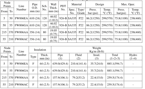
Table 1 : Main Feedwater System Piping Information Node
Points Material Design Max. Oper.
From To Line Number Pipe O.D. mm (in) Sch. No. Wall Thick. mm (in) PDT No. Spec.
No. Type/ Grade Press. bar (psi) Temp.
°C (°F)
Press. bar(psi)
Temp.
°C (°F)
5 50 FW006EA 610 (24) 120 46.02
(1.812) 926-B SA335 P22 86.2(1250) 299(570) 75.8(1100) 238(460)
50 55 FW006GA 610 (24) 120 46.02
(1.812) 926-B SA335 P22 86.2(1250) 299(570) 75.8(1100) 238(460)
215 370 FW006AA 356 (14) 80 19.05
(0.75) 926-B SA335 P22 86.2(1250) 299(570) 75.8(1100) 238(460)
55 210 FW006AC 356 (14) 80 19.05
(0.75) 926-B SA335 P22 86.2(1250) 299(570) 75.8(1100) 238(460)
Node
Points Insulation
Weight Kg/m (lb/ft) From To Line Number Type Thick. mm (in) Pipe (1) Fluid (2) Insul. (3) Total (1+2+3) Hydro (1+4)
5 50 FW006EA F 64 (2.5) 639.0(429.4) 210.4(141.4) 35.7(24.0) 885.1(594.7) -
50 55 FW006GA F 64 (2.5) 639.0(429.4) 210.4(141.4) 35.7(24.0) 885.1(594.7) -
215 370 FW006AA F 64 (2.5) 157.9(106.1) 79.2(53.2) 22.4(15.0) 259.5(174.4) -
55 210 FW006AC F 64 (2.5) 157.9(106.1) 79.2(53.2) 22.4(15.0) 259.5(174.4) -
2. Analysis Methodology
1) Analysis Method
The influence analysis is performed for the two cases: The first case is to include OBE load in the Service Level B load combination of stress analysis and the second case is to exclude OBE from the combination. FRS(Floor Response Spectra) for OBE are generated by approximating FRS for SSE since they are not available for APR1400 due to exclusion of OBE.
Piping stress analyses for both cases with and without inclusion of OBE are performed and reviewed whether they meet the requirements of code allowable stress and pipe break postulation.
2) Computer Aided Design Code
Computer program used for piping stress analysis is Sargent & Lundy’s PIPSYS(Integrated Piping Analysis System) which is a linear and three-dimensional finite element analysis program with menu-driven interactive modules to pre- and post-process data for the analysis and stress evaluation of a piping system.
3. Design Variance Review
1) Generation of OBE Input Motion
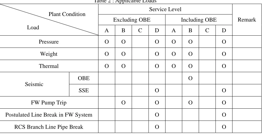
Table 2 : Applicable Loads
Service Level
Excluding OBE Including OBE Plant Condition
Load A B C D A B C D
Remark
Pressure O O O O O O
Weight O O O O O O
Thermal O O O O O O
OBE O
Seismic
SSE O O
FW Pump Trip O O O O
Postulated Line Break in FW System O O
RCS Branch Line Pipe Break O O
A) Dead Weight Load
The effect of sustained piping weight on the piping system is considered. Sustained piping weight is comprised of but is not limited to the weight of pipe, insulation and in-line pipe components.
B) Thermal Load
The flexibility analysis for thermal expansion of piping system and thermal expansion movements at steam generator nozzle is performed.
C) Seismic Inertia Load
The seismic excitation of the base causes acceleration and movement of the building structure, which gives rise to the movement and acceleration of piping systems and equipment attached to the building structure. Inertia stress of piping system caused by the acceleration of the building structure is regarded as primary stress.
D) Seismic Anchor Movement
The effect of differential seismic anchor movements at building structures and steam generator nozzles are considered. During earthquake, movement of the base causes the acceleration and movement of the building structure, which also causes the acceleration and movement of the piping systems and equipment attached to the building structure. The analysis for differential seismic anchor movements is performed using static analysis method. Pipe stress caused by displacement of the building structure is regarded as secondary stress and is combined with thermal expansion stress.
E) System Operating Transient Load
The analysis of system operating transient (Feedwater Pump Trip) identified in the system design specification is performed. The effect of fluid movement on the piping system is evaluated by performing dynamic transient analysis based on the piping layout configuration.
3) Load Combination
Table 3 : Main Feedwater System Load Combination
Load Combination ASME Code
Eq. No. Excluding OBE Including OBE Remark
8 DPRS+WGHT DPRS+WGHT
9b PPRS+WGHT+FPTR PPRS+WGHT+[FPTR2+OBE2]1/2
9d PPRS+WGHT+(FPTR 2
+SSE2+ BLPB2)1/2
PPRS+WGHT+[FPTR2+SSE2+ BLPB2]1/2
10 THER TRER+SAM(OBE)
10b THER+SAM(SSE) -
11 DPRS+WGHT+THER DPRS+WGHT+THER+SAM(OBE)
DPRS: Design Pressure, PPRS: Peak Pressure, OBE: Operating Basis Earthquake, SSE: Safe Shutdown Earthquake, WGHT: Weight, SAM: Seismic Anchor Motion, FPTR: Feedwater Pump Trip, BLPB: RCS Branch Line Pipe Break Motion, THER: Thermal
ANALYSIS RESULTS
1. Code Stress Requirement
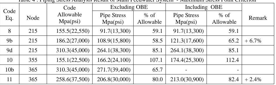
Maximum Pipe stress calculated for each load combination of the Code equation is compared against allowable stress limit and shown below in Table 4. Cases for both with and without considering OBE are shown separately.
Table 4 : Piping Stress Analysis Result of Main Feedwater System - Maximum Stress Point Criterion Excluding OBE Including OBE
Code
Eq. Node
Code Allowable
Mpa(psi)
Pipe Stress Mpa(psi)
% of Allowable
Pipe Stress Mpa(psi)
% of
Allowable Remark
8 215 155.5(22,550) 91.7(13,300) 59.1 91.7(13,300) 59.1
9b 215 186.2(27,000) 108.9(15,800) 58.5 121.3(17,600) 65.2 + 6.7%
9d 215 310.3(45,000) 264.1(38,300) 85.1 264.1(38,300) 85.1
10 355 155.1(22,500) 166.2(24,100) 107.1 174.4(25,300) 112.4
10b 365 310.3(45,000) 271.7(39,400) 65.7 - -
11 365 258.6(37,500) 206.8(30,000) 80.0 213.0(30,900) 82.4 + 2.4%
As shown in the above table, all stresses in the piping system meet the allowable stresses of applicable Code equations, and it can be seen that the design of selected FW piping system is governed by Service Level D stress limit rather than Service Level B. It is also can be seen that the OBE contributes to 6.7% of the Eq.9B stress and 2.4% for Eq.11 stress.
2. Regulatory Pipe Break Requirement
Pipe stress criteria to determine rupture location per reference 9 is checked for both cases with and without considering OBE and the results are shown on Table 5 below.
Table 5 : Review of pipe stress criteria for break location selection Calculated Max. Stress
Mpa(psi) Analysis
Methodology
Eq.9B Eq. 10 Eq.9b + Eq.10
Stress Limits for Eq.9b + Eq.10
Mpa(psi)
% of Allow.
CONCLUSION
According to the analysis result of Main Feedwater Piping inside Containment Building of APR1400, the effect of excluding OBE load is minimal since 1) Service Level D load condition governs the piping design even for the case with OBE included. Note that inclusion of OBE in Eq.9B only increases combined stress by 6.7%. 2) No intermediate pipe break needs to be postulated in both cases and the difference in pipe break criteria stresses for both cases is only 4.8 % of the allowable stress.
Therefore, It can be concluded that 1) there will be no reduction in safety margin of piping system due to the exclusion of OBE load in the design if OBE is equal to or less than one-third of SSE, 2) the effect of not considering OBE in the design of piping system is minimal, and 3) the primary stress of piping system is generally governed by SSE.
REFERENCES
[1] PIPSYS Program, Sargent & Lundy Prog. No. PIP037026230, Version 3.0.
[2] ASME Boiler and Pressure Vessel Code, Section Ⅲ, 1992 Edition with 1992 and 1993 Addenda. [3] Federal Register, Vol. 64, No. 183, 10CFR50.55a "Final Rule", Sep. 22, 1999.
[4] APR1400 General Piping System Design Specification N-001-END407-001 Rev.0 dated 04/30/98. [5] APR1400 FW Piping System Design Specification N-541-END407-001, Rev.A.
[6] APR1400 Piping Design Table and Standard Details, N-001-END443-001, Rev.0 [7] APR1400 FW System Piping Drawings N-313-END193-103FW.
[8] NRC Policy Issue, SECY-93-087, April 2, 1993.
[9] BPT MEB 3-1, “Postulated Rupture Locations in Fluid System Piping Inside and Outside Containment" SRP 3.6.2, Rev. 2 dated June 1987.
[10] NUREG-1061, Evaluation of Seismic Designs, April 1985. [11] NUREG-1367, Functional Capability of Piping System: Nov.1992.