GALVIN, CASEY JAMES. Copolymer Synthesis and Characterization by Post-Polymerization Modification. (Under the direction of Dr. Jan Genzer).
This PhD thesis examines the physical behavior of surface-grafted polymer assemblies (SGPAs) derived from post-polymerization modification (PPM) reactions in aqueous and vapor enriched environments, and offers an alternative method of creating SGPAs using a PPM approach. SGPAs comprise typically polymer chains grafted covalently to solid substrates. These assemblies show promise in a number of applications and technologies due to the stability imparted by the covalent graft and ability to modify interfacial properties and stability. SGPAs also offer a set of rich physics to explore in fundamental investigations as a result of confining macromolecules to a solid substrate. PPM reactions (also called polymer analogous reactions) apply small molecule organic chemistry reactions to the repeat units of polymer chains in order to generate new chemistries. By applying a PPM strategy to SGPAs, a wide variety of functional groups can be introduced into a small number of well-studied and well-behaved model polymer systems. This approach offers the advantage of holding constant other properties of the SGPA (e.g., molecular weight, MW, and grafting density, σ) to isolate the effect of chemistry on physical behavior.
Using a combination of PPM and fabrication methods that facilitate the formation of SPGAs with position-dependent gradual variation of σ on flat impenetrable substrate, the influence of polymer chemistry and σ is examined on the stability of weak polyelectrolyte brushes in aqueous environments at different pH levels. Degrafting of polymer chains in SGPAs exhibits a complex dependence on side chain chemistry, σ, pH and the charge fraction (α) within the brush. Results of these experiments support a proposed mechanism of degrafting, wherein extension of the grafted chains away from the substrate generates tension along the polymer backbone, which activates the grafting chemistry for hydrolysis. The implications of these findings are important in developing technologies that use SGPAs in aqueous environments, and point to a need for potential alternative grafting chemistries.
results in exposure of electrostatic charges without counterions. Using substrates bearing the aforementioned σ gradient of polymeric grafts, evidence of inter- and intramolecular complex formation is presented.
by
Casey James Galvin
A dissertation submitted to the Graduate Faculty of North Carolina State University
in partial fulfillment of the requirements for the degree of
Doctor of Philosophy
Chemical Engineering
Raleigh, North Carolina 2014
APPROVED BY:
_______________________________ ______________________________
Dr. Jan Genzer Dr. Orlin Velev
Committee Chair
_______________________________ ______________________________
DEDICATION
BIOGRAPHY
Casey J. Galvin hails from Milwaukee, WI, and attended Marquette University High School. He graduated with a degree in Chemical Engineering from Northwestern University in Evanston, IL in 2007. While there, he worked with Prof. Randy Snurr and then-postdoc Dr. David Dubbeldam conducting molecular simulations of alkane adsorption in zeolites.
Following undergraduate studies, CJG enrolled in the graduate program of the Department of Chemical & Biomolecular Engineering at North Carolina State University, Raleigh, NC. He joined the group of Prof. Jan Genzer and has worked on projects related to the behavior of polymer chains grafted to solid interfaces that incorporate elements of chemistry and physics.
During his tenure in the Genzer group, he received an NSF EAPSI Fellowship to work with Prof. Taihyun Chang at POSTECH in South Korea, and has worked as a visiting researcher with Prof. Kookheon Char at Seoul National University in South Korea, and Dr. Jiři Šrogl at the Institute of Organic Chemistry and Biochemistry in Prague. CJG also collaborated with Prof. Svetlana Santer from the University of Potsdam during her sabbatical at NCSU.
ACKNOWLEDGEMENTS
The person most responsible for this PhD Thesis is my partner, Lauren Dembeck, who has provided significant professional and personal support since our fairytale meeting. She heard the hypotheses and results contained in this document before anyone else, and continues to provide constructive questions, comments and looks of confusion when I am not making any sense.
I am grateful to my advisor, Jan Genzer, for letting me do a second PhD, which starts roughly at Chapter 4. You also provided my first international exposure, resulting in a fundamental shift in my world outlook and life’s pursuits. Those experiences will remain relevant long after this work has faded into scientific obscurity.
The Genzer group itself has been integral to the work contained in this thesis. I must give special thanks to Drs. Young Kuk Jhon and Evren Özçam, who provided an early introduction and on-going training in scientific research. To the rest of the Genzer group alumni, current members and visitors, I extend a thank you for listening to my GM presentations, being flexible about instrument schedules and generally making day-to-day life in the lab enjoyable.
I have enjoyed a number of collaborative efforts during my PhD tenure. I had the distinct pleasure of working with Prof. Svetlana Santer during her sabbatical at NCSU. I want to acknowledge also my collaboration with Dr. Mike Dimitriou, a one-time NIST post-doc, who performed the neutron and X-ray reflectivity measurements in Chapter 4. I am similarly appreciative to Prof. J-P Maria and his students Edward Sachet and Chris Shelton for facilitating AFM measurements in Chapters 3 and 6.
TABLE OF CONTENTS
LIST OF TABLES ... VIII
LIST OF FIGURES ... IX
1.
INTRODUCTION AND DISSERTATION SCOPE ... 1
1.1 Introduction ... 2
1.2 References ... 6
2.
APPLICATIONS OF SURFACE-GRAFTED MACROMOLECULES DERIVED
FROM POST-POLYMERIZATION MODIFICATION REACTIONS* ... 7
2.1 Introduction ... 8
2.1.1 Overview of Polymer Brushes ... 12
2.1.2 Modification Chemistries ... 15
2.2 Stimuli Responsive Brushes ... 17
2.2.1 Weak Polyelectrolytes ... 18
2.2.2 Strong Polyelectrolytes ... 19
2.3 Selected case studies involving PPM on macromolecular grafts ... 21
2.3.1 Altering Wetting Behavior of Surfaces ... 22
2.3.2 Ion Transport Barriers ... 25
2.3.3 Manipulating Nanoparticles ... 30
2.3.4 Incorporating Biological Moieties into Polymer Brushes ... 38
2.3.5 Cellular Studies ... 51
2.4 Summary and outlook ... 59
2.5 Acknowledgement ... 62
2.6 Glossary of used abbreviations and symbols ... 63
2.7 References ... 65
3.
DEGRAFTING OF POLYELECTROLYTE BRUSHES FROM SOLID
SUBSTRATES IN AQUEOUS ENVIRONMENTS ... 80
3.1 Introduction ... 81
3.2 Experimental ... 83
3.2.1 General Methods and Materials ... 83
3.2.2 Sample Preparation ... 83
3.2.3 Incubation Experiments ... 84
3.3 Results and Discussion ... 86
3.3.1 Dense PMAA Brush Degrafting ... 86
3.3.2 Sparse PMAA Brush Degrafting ... 91
3.3.2 PDMAEMA Brush Degrafting ... 94
3.3.4 PDMAEMA Brush Morphology ... 100
3.4 Conclusion ... 103
3.5 References ... 105
4.
SWELLING OF POLYELECTROLYTE AND POLYZWITTERION BRUSHES
BY HUMID VAPORS ... 107
4.1 Introduction ... 108
4.2 Experimental Section ... 109
4.2.1 General Methods and Materials ... 109
4.2.2 Sample Preparation ... 110
4.2.3 Characterization Techniques ... 110
4.2.4 PPM conversion calculations ... 112
4.2.5 Reduced grafting density (Σ) calculation: ... 112
4.3 Results and Discussion ... 113
4.4 Conclusion ... 127
4.5 Acknowledgement ... 127
4.6 References ... 128
5.
POLYELECTROLYTE BRUSH SWELLING BY WATER AND ALCOHOL
VAPORS ... 130
5.1 Introduction ... 131
5.2 Experimental ... 133
5.2.1 General methods and materials ... 133
5.2.2 Sample Preparation ... 134
5.2.3 Characterization Techniques ... 135
5.3 Results and Discussion ... 137
5.3.1 PDMAEMA Gradient Brush Swelling ... 137
5.3.2 Grafted Versus Spuncast Films ... 142
5.3.3 Influence of Amino Alkyl Chain Length ... 149
5.3.4 Swelling by Organic Alcohols... 155
5.4 Conclusion ... 159
6.
SURFACE-GRAFTED POLYMER ASSEMBLIES VIA GRAFTING-THROUGH
POLYMERIZATION ... 163
6.1 Introduction ... 164
6.2 Experimental ... 165
6.2.1 General methods and materials ... 165
6.2.2 Sample Preparation ... 165
6.2.3 Characterization techniques... 166
6.3 Results and Discussion ... 166
6.3.1 Homogeneous Grafting-Through Samples ... 166
6.3.2 Gradient Grafting-Through Samples ... 175
6.4 Conclusion ... 182
6.5 References ... 183
7.
OUTLOOK... 184
7.1 Future Work for Polymer Brush Degrafting ... 185
7.2 Future Work for Polymer Brush Vapor Swelling ... 188
7.3 Future Work for Grafting-through Polymerization ... 190
LIST OF TABLES
LIST OF FIGURES
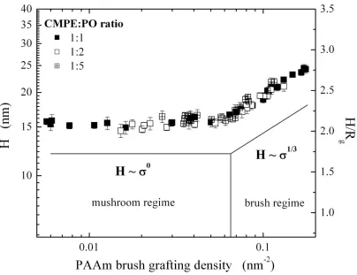
Figure 2.2. A Schematic representing conformations of surface-anchored polymers in brush (left) and mushroom (middle) regimes in a good solvent. Also shown is the conformation of surface-tethered polymer in a poor solvent. ... 13 Figure 2.3. Wet thickness of the poly(acrylamide) (PAAm) brush (H) as a function of the PAAm
brush grafting density. Reproduced with permission from the American Chemical Society. .... 14 Figure 2.4. Selected coupling reactions employed in PPM processes involving coupling of various
functional groups with pendent: a) phenyls, b) epoxys, c) hydroxyls, d) tertiary amines, e) vinyls, f) t-butyls and aminoacids, g) alkynes... 16 Figure 2.5. (A) Schematic depiction of the increase in swollen thickness of a polymer brush in a
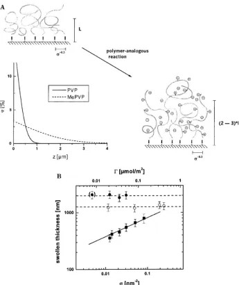
good solvent after the conversion of the neutral brush into the charged species due to the introduction of electrostatic forces. (B) Brush thickness as a function of graft density for neutral and charged brushes. The experimental results agree well with the predicted scaling laws, which are indicated as lines in the figure (L~σ0.33
for the neutral brushes and L~σ0 for the polyelectrolyte brushes). Reproduced with permission from the American Chemical Society. . 20 Figure 2.6. Schematic illustrating the conformations of polymer grafts in concave, and on flat and
convex surfaces. The spatial distribution of the modifying agent after the PPM depends on the curvature of the substrate. The smallest degree of confinement will be present for chains grafted to substrates with large positive curvatures (κ). Decreasing κ from large positive to small positive, zero or even negative values will increase the degree of confinement. As a result, the modifying agent will only access the topmost regions of the polymeric grafts. While chains grafted to small particles can be modified nearly completely, those attached inside small pores will undergo PPM to only a limited degree. ... 21 Figure 2.7. (left panel) Preparation of PDMDOMA-grafted silicon wafer via surface-initiated atom
Schematic procedure for photopatterning “yne”-containing polymer brush surfaces with sequential thiol-yne reactions. (right panel) Condensation images of sequential thiol-yne micropatterned brushes showing water droplets selectively nucleating on the hydrophilic MPA areas: (a) MPA/DDT (square/bars), 300 mesh; (b) MPA/DDT (squares/bars), 2000 mesh; (c) inverse DDT/MPA (squares/bars), 300 mesh; (d) Sunlight MPA/DDT (squares/bars); (e) static water contact angle measurements showing pH responsive reversible wettability of MPA surfaces prepared outdoors in sunlight. Note: Color variations result from thin film interference under humid conditions. Reproduced with permission from the American Chemical Society. . 23 Figure 2.9. Changes in wettability corresponding to a Au surface modified with PMETAC brushes
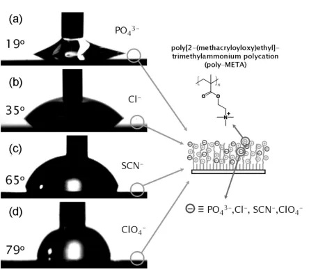
(h = 20 nm) when their corresponding counterions are: a) PO43–, Cl–,b) SCN–, and c) ClO4–. The schematic depicts the structure of the cationic polyelectrolyte brush. Reproduced with permission from Wiley. ... 24 Figure 2.10. (A) Stepwise covalent modification of the ITO electrode surface to yield the mixed
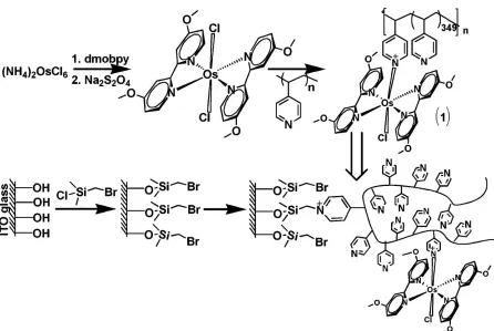
polymer brush composed of P2VP and PAA. (B) The polymer brush permeability for the differently charged redox probes controlled by the solution pH value: a) the positively charged protonated P2VP domains allow the electrode access for the negatively charged redox species; b) the neutral hydrophobic polymer thin-film inhibits the electrode access for all ionic species; c) the negatively charged dissociated PAA domains allow the electrode access for the positively charged redox species. Reproduced with permission from Wiley. ... 27 Figure 2.11. Functionalization of poly(4-vinyl pyridine) (P4VP) with the pendant redox groups and
modification of the ITO electrode with the resulting redox polymer. Reproduced with permission from the American Chemical Society. ... 28 Figure 2.12. (a) Reversible pH-Controlled Transformation of the Redox-Polymer Brush on the
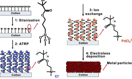
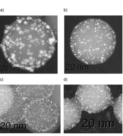
Figure 2.13. Schematic illustration of the process of preparing conductive cotton yarns. The dimension is not drawn to scale. Reproduced with permission from the American Chemical Society. ... 32 Figure 2.14. TEM images from samples a) Au73Pt27, b) Au55Pt45, c) Au45Pt55, and d) Au25Pt75.
For sake of clarity the contrast has been inverted. Reproduced with permission from Wiley. ... 33 Figure 2.15. (left panel) Differential interference contrast (DIC) micrographs of mineralized PMAA
brushes of varying grafting density. The insert in the image of the brush generated from a surface modified with χ1solution
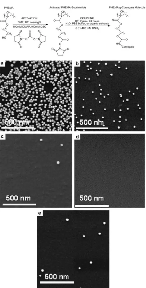
= 1.0 was taken between crossed polarizers and illustrates the amorphous nature of the deposited CaCO3 layer. (right panel) Advancing and receding water contact angles on PMAA brushes with varying grafting densities before and after incubation with aqueous 10 mM CaCl2 solution. Polymerizations were carried out at 25°C and pH 9 for 30 min using the following polymerization conditions: NaMA/CuBr/CuBr2/bipy/water = 200:2:0.4:5:1400. Reproduced with permission from the American Chemical Society. ... 34 Figure 2.16. (top panel) Functionalization of PHEMA side chain using DSC activation and
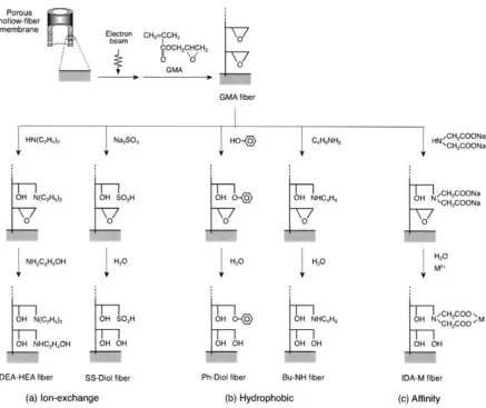
subsequent amination. (bottom panel) Relative affinity of post-functionalized PHEMA brushes to adsorption of 30 nm citrate-capped Au nanoparticles. (a) PHEMA-g-PEG50 (13015 NP/mm2); (b) PHEMA-g-PEG20 (416.8 NP/mm2); (c) PHEMA-g-C16 (0.80.2 NP/mm2); (d) PHEMA-g-C8F15 (0 NP/mm2); (e) pristine PHEMA (3.21.8 NP/mm2). Reproduced with permission from Elsevier. ... 37 Figure 2.17. Preparation scheme of functional polymer brush grafted onto the pore surface of a
porous hollow-fiber membrane. Reproduced with permission from Elsevier... 39 Figure 2.18. Synthesis of protein-binding poly(MES) brushes on Au surface. Reproduced with
permission from the American Chemical Society. ... 40 Figure 2.19. Scanned fluorescence images of DNA (N3-20mer-FAM) immobilization on
hydrophobic (top) and hydrophilic (bottom) surfaces via “click” reaction (left) and nonspecific physisorption (right). The spin-coating solution concentration is 0.5%. Reproduced with permission from the American Chemical Society. ... 41 Figure 2.20. (top panel) (A) Direct immobilization of proteins on polymer brushes in a two-step
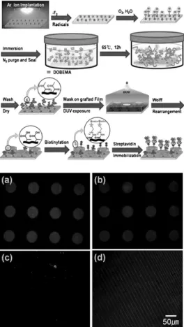
(bottom panel) SA immobilization levels (determined by fluorescence assay) on POEGMA-360 brushes using a range of coupling agents. Red bars: hydroxyl-terminated brushes were directly activated with the corresponding coupling agents depicted (a, no coupling agent) before incubation for 18 h in a SA solution. Green bars: hydroxyl-terminated brushes were first functionalized with glutaric or succinic anhydride and incubated with SA (b) without NHS/EDC activation and (c) with NHS/EDC activation. Error bars represent standard deviations for n = 3. Reproduced with permission from the American Chemical Society. ... 43 Figure 2.21. (top panel) Illustration of graft polymerization, UV exposure, and protein
immobilization. (bottom panel) Confocal fluorescence images of SAv-Rh immobilized on biotinylated region of 12 h graft-polymerized PTFE films prepared under different ion-irradiation conditions; circle patterns (50 µm) (a) at 5 × 10¹⁴ ions/cm2, (b) 1 × 10¹⁵ ions/cm2, (c) 5 × 10¹⁵ ions/cm2, and (d) finer line (5 µm) patterns at 5 × 10¹⁴ ions/cm2. Reproduced with permission from the Royal Society of Chemistry. ... 45 Figure 2.22. Polymeric brushes as functional templates for immobilizing Ribonuclease A.
Reproduced with permission from the American Chemical Society. ... 46 Figure 2.23. (a) A mixture of bradykinin (+ charge at pH 7) and buccalin (− charge at pH 7) is
placed on a brush nanosponge-coated gold surface (w/copolymer 1) and on a conventional MALDI plate. Since buccalin has reduced ionization efficiency in the presence of bradykinin it has a weak MALDI signal even though there is a 10-fold excess of buccalin to bradykinin in solution. (b) After 30 s exposure, the bradykinin has been adsorbed by the nanosponge brush and the eluant is removed and placed onto a conventional MALDI plate; only buccalin is detected. (c) The nanosponge is then ‘squeezed’ by treating with a drop of 10% formic acid, which collapses and neutralizes the brush and releases the bradykinin for subsequent MALDI analysis. Reproduced with permission from the American Chemical Society. ... 49 Figure 2.24. Synthetic ATRP strategy for the preparation of Si/SiO2//poly(SMAGlc) polymer brush.
(i) 10/3 v/w monomer solution in veratrole, DPtheo=200, 12 h, 85 C; (ii) 80% TFA solution, 30 min, RT; (iii) 0.2 M SO3.py solution in anhydrous pyridine, 2 h, 85 C, sat. NaHCO3 solution. Reproduced with permission from Wiley. ... 50 Figure 2.25. (top panel) Schematic description of the synthesis of polySPM (sulfonate brush).
brushes. Both images represent wafer pieces positioned in a Petri dish and covered with growth agar. Reproduced with permission from the American Chemical Society... 52 Figure 2.26. Dependence of the biocidal activity of the surfaces prepared by “grafting onto” and by
“grafting from” on the average density of QA groups. Reproduced with permission from the American Chemical Society. ... 53 Figure 2.27. (top panel) Oriented Grafting of MAG-Cys Derivative on Poly(MOE2MA-co-HOEGMA) Brushes via a PMPI heterolinker. (bottom panel) CLSM images of MAG-Cys-functionalized poly(MEO2MA-co-HOEGMA) [33:67] brush incubated in the presence of L. ivanovii and subsequently stained with the LIVE/DEAD viability kit: (A) green channel image
corresponding to alive stained bacteria; (B) red channel image corresponding to dead bacteria; (C) overlay image built from (A) and (B). Reproduced with permission from the American Chemical Society... 54 Figure 2.28. (left panel) Schematic of brush functionalization with peptides. (right panel)
Proliferation of HUVECs on GGGRGDS and GGGRDGS functionalized 20 nm thick PHEMA, PPEGMA6 and PPEGMA10 brushes. (a) HUVEC density 4, 24 and 48 h post-seeding. (b) Photomicrographs of HUVECs on a 20 nm thick PPEGMA10 brush 4, 24 and 48 h post-seeding. The peptide concentration in the functionalization solution was 1 mm. Scale bar: 50 μm. Reproduced with permission from Elsevier. ... 56 Figure 2.29. (top panel) Preparation of RGD-modified polymer brushes grafted from immobilized
precursors on gold by photopolymerization: (a,b) Photografting of PMAA brushes from immobilized photoiniferter DTCA/ODT SAMs; (c) immobilization of RGD peptides; and (d) chain extension via photografting of a top PMAA brush layer. (bottom panel) Immunofluorescence images of MG63 cells on the studied surfaces: (a) PMAA, (b,c) PMAA−RGD, and (d) PMAA−RGD−PMAA after 6 h of contact. Reproduced with permission from the American Chemical Society. ... 58 Figure 2.30. Schematic showing the approach pioneered by the Okano group to create continuous
Figure 2.31. Position along A0.5B0.5 300-mers as a function of monomer type (B = -1, A = +1) tethered at surface densities ρ = 0.001 (left panel) and 0.010 (right panel) polymers/area for kT/|εAA| = 6.0 and RBA = 5.0. Typical chain conformations are shown for each case in the upper part (A = grey, B = red). Reproduced with permission from the American Chemical Society. . 60 Figure 2.32. Number of peer-reviewed publications describing the PPM process. ... 61 Figure 3.1. a) Influence of σ on tension generated along chain backbone. b) Influence of α on tension
generated along chain backbone. Cartoon is drawn for a polyacid (e.g., PMAA). Counterions not depicted for clarity. c) Proposed degrafting mechanism where tension generated along chain backbone activates grafting chemistry for hydrolysis by hydroxyl ions. Neighboring chains, counterions and charges on degrafted chain not depicted for clarity. Cartoons not drawn to scale. ... 82 Figure 3.2. a-c) Thickness profiles as a function of position on the substrate for PtBMA brushes
(black squares) and PMAA brushes at 0 and 24 hours of incubation (red circles and blue triangles, respectively) in buffer solutions at pH 4 (a), 7.4 (b) or 9 (c). d-f) Data from panels a-c comprising PMAA at 0 hours normalized by PtBMA thickness (red circles) and PMAA at 24 hours normalized by PMAA at 0 hours incubation (blue squares) for buffer solutions at pH 4 (d), 7.4 (e) or 9 (f). ... 88 Figure 3.3. a) Thickness of PMAA brushes measured at a wafer position of 3.0 cm (densest σ)
plotted as a function of incubation time for samples incubated at pH 9 (black squares), pH 7.4 (red circles) and pH 4 (blue triangles). b) The data in panel a) incubated by the thickness measured at 24 hours incubation. c) Calculated values of β derived from IR-VASE data (see text). ... 90 Figure 3.4. Thickness of PMAA brushes normalized by the thickness measured at 24 hours
incubated in buffers at pH 4, pH 7.4 and pH 9. ... 94 Figure 3.5. a-c) Thickness profiles as a function of position on the substrate for PDMAEMA brushes
Figure 3.6. Thickness of PDMAEMA brushes at 168 hours of incubation normalized by the thickness measured at 24 hours in buffers at pH 9 (black up-triangles), pH 7.4 (red down-triangles) and pH 4 (blue diamonds). ... 99 Figure 3.7. AFM micrographs depicting surface topography of PDMAEMA brushes measured at a
substrate position of 3.75 cm (dense α) following incubation for 24 hours (center column) or 120 hours (right column) in buffer solutions at pH 4 (top row), pH 7.4 (middle row) or pH 9 (bottom row). Micrographs are 4 μm x 4 μm. Scale bars are 1 μm. Color varies over a range of 15 nm; absolute range values chosen to emphasize morphology. ... 101 Figure 3.8. AFM micrographs depicting surface topography of a PDMAEMA brush expressing a
gradient in σ incubated in a pH 4 buffer for 120 hours measured at various points on the substrate. The plot shows the initial thickness and thickness after incubation (to which the micrographs correspond). Color-coded numbered positions correspond to location of the AFM micrograph. Micrographs are 4 μm x 4 μm. Scale bars are 1 μm. Color varies over a range of 15 nm; absolute range values chosen to emphasize morphology. ... 102 Figure 4.1. Neutron reflectivity profiles of PDMAEMA brush at different RH levels (open circles)
showing fits (solid lines) used to derive the SLD profiles in Figure 4.2a. The data for RH higher than 10% have been shifted vertically downward for clarify. ... 114 Figure 4.2. a) SLD profiles at various RH levels derived from fitting NR data in Figure 4.1. b)
Illustration of proposed D2O enrichment at polymer/air interface at low RH (bottom), leading to more uniform hydration and chain stretching at higher RH (top). c) Compilation of swelling factors calculated from thickness values derived from SE data (squares and circles), XR data (upward triangle) and NR data (downward triangle). The right ordinate (diamonds) depicts the integrated area under the solid lines in the SLD profiles in Figure 4.2a. ... 115 Figure 4.3. Polyelectrolyte and polyzwitterion brushes derived from PPM reactions. ... 117 Figure 4.4. FT-IR data of polymer brush samples collected at ambient conditions (≈45 % RH).
Orange = PDMAEMA; Purple = PDMAEMA-MeI; Green = PDMAEMA-PrI; Black = PDMAEMA-PS. Noise at 1500 cm-1 and 3750 cm-1 originates from atmospheric water due to the open setup of the FT-IR microscope. A break in the abscissa has been inserted to omit peaks associated with CO2 that result from the open setup of the FT-IR microscope. ... 119 Figure 4.5. Solid lines denote predicted swelling factors as a function of the weight fraction of
PDMAEMA-PS. These lines are calculated following a previously described procedure18. The solid symbols represent measured swelling factors. The quaternized samples are well-described by this model. PDMAEMA-PS follows a trend requiring a lower density. ... 120 Figure 4.6. a) Swelling factor for PDMAEMA (squares), PDMAEMA-MeI (circles), and
PDMAEMA-PrI (triangles) calculated from thickness values derived from fitting the SE data. Closed and open symbols represent results from different runs on the same sample. b) Solvent fraction of the polymer brush determined by fitting the SE data. Closed and open symbols represent results from different runs on the same sample. c) Flory-Huggins χ parameter values calculated from the data in 2B. Closed and open symbols correspond to results from different runs on the same sample. The error bars on the abscissa represent the range of RH levels inside the cell during a measurement for all panels. ... 122 Figure 4.7. a) Swelling factor values calculated from brush thicknesses obtained by fitting SE data.
Inset: Thickness of brush at ≈10 % RH (KOH thickness) and PDMAEMA-PS brush grafting density (σ) plotted against position on the substrate and the initiator fraction on the substrate determined by water contact angle measurements. b) Solvent fraction inside PDMAEMA-PS brush determined by fitting SE data plotted against swelling factor values in 3a. Black line is the expected trend (see text). c) Values of Flory-Huggins interaction parameter, χ, calculated from data in 3b. d) Clockwise from upper left: illustration of zwitterion complex; low σ region forming predominantly intramolecular complexes; high σ region forming predominantly intermolecular complexes; medium σ region unable to form complexes. ... 125 Figure 5.1. Schematic illustrations of polymer parameters considered in vapor swelling experiments.
The upper row depicts a spuncast polymer film (left) and a grafted polymer film (right) on the substrate. The center row illustrates a grafted polymer assembly expressing a gradient in σ, which leads to a variation in film height. The bottom row shows two grafted assemblies comprising chains of lower (left) or higher (right) molecular weight. The cartoons are not drawn to scale. ... 132 Figure 5.2. Chemical structures of the polymer chains used in vapor swelling experiments. ... 133 Figure 5.3. a) Swelling factor calculated from thickness values derived from fitting SE data for a
measurements. b) Solvent fraction inside the PDMAEMA brush at each measurement point determined by fitting SE data. c) Solvent fraction data from Figure 5.3b plotted against swelling factor data from Figure 5.3a. Black line is the expected trend (see text). d) Values of Flory-Huggins interaction parameter, χ, calculated from data in Figure 5.3b. Inset: Detail of plot from 75 % RH to 100 % RH. ... 139 Figure 5.4. Top-down schematic of the projected area of a grafted polymer chain (large orange
circles) and the resulting interstitial void space being filled with water molecules (small blue circles). The unmodified PDMAEMA brush (top row) has more void space at intermediate grafting densities (σ) than at high σ, resulting in a more hydrophobic brush environment. The betainized PDMAEMA brush (PDMAEMA-PS; bottom row) expresses a hydrophilic zwitterionic side chain chemistry (red corona) that extends into the void space. At intermediate σ, neighboring chains cannot form zwitterionic complexes, resulting in a hydrophilic environment. At high σ, the side chains in PDMAEMA-PS can form zwitterionic complexes (overlapping red corona regions) that compensate the hydrophilic charges and result in a more hydrophobic brush environment. ... 141 Figure 5.5. IR-VASE data collected at an incidence angle of 50o with a resolution of 4 cm-1 for a
spuncast PDMAEMA film (blue) and an identical film after exposure to MeI vapors for 48 hours (cyan). The disappearance of peaks at 2750 cm-1 and 2800 cm-1 is associated with the conversion of side chain tertiary amines to quaternary ammonium groups in PDMAEMA18. Following quaternization, a peak at 3450 cm-1 associated with water19 appears in the PDMAEMA-MeI sample. ... 144 Figure 5.6. a) Swelling factor calculated from thickness values derived from fitting SE data for
PDMAEMA and PDMAEMA-MeI brushes and spuncast films. b) Solvent fraction inside the PDMAEMA brushes and spuncast films determined by fitting SE data. c) Solvent fraction data from Figure 5.6b plotted against swelling factor data from Figure 5.6a. Black line is the expected trend (see text). d) Values of Flory-Huggins interaction parameter, χ, calculated from data in Figure 5.6b... 146 Figure 5.7. a) Swelling factor calculated from thickness values derived from fitting SE data a
5.7a. Black line is the expected trend (see text). d) Values of Flory-Huggins interaction parameter, χ, calculated from data in Figure 5.7b. ... 150 Figure 5.8. Water cluster number (Nc) calculated using Zimm-Lundberg (closed symbols) and
Brown (open symbols) analyses plotted as a function of RH % for brushes comprising PDMAEMA (orange data), PDMAEMA-MeI (purple data), PDMAEMA-PrI (green data) and PDEAEMA (dark cyan data). ... 153 Figure 5.9. a) Swelling factor in methanol calculated from thickness values derived from SE data
collected at various incubation times for brushes comprising PDMAEMA (orange data), PDMAEMA-MeI (purple data), PDMAEMA-PrI (green data) and PDEAEMA (dark cyan data). b) Swelling factor in ethanol calculated from thickness values derived from SE data for same samples. c) Methanol fraction inside the polymer brush samples. d) Ethanol fraction inside the polymer brush samples. ... 156 Figure 6.1. Synthesis scheme for grafting-through polymerization using 11-BUTS (black and red
molecules), DMAEMA (blue molecules) and tBMA (green molecules). ... 168 Figure 6.2. The left abscissa shows the relationship between PtBMA film thickness produced by
grafting through SGMs (red squares) and Mn of bulk PtBMA recovered from the polymerization solution. The right abscissa shows the correlation between volume % of tBMA monomer in the polymerization solution (blue squares) and Mn of bulk PtBMA recovered from the polymerization solution. ... 169 Figure 6.3. a) Dependence of water contact angle (WCA) on PtBMA film thickness for sample sets 1
(red squares) and 2 (black circles). The PtBMA film thickness has been offset by a constant factor for each sample set so that the initiator-only sample has a thickness of zero. b) Calculated Cassie-Baxter fraction of PtBMA from WCA in panel a. See Equation 6.2 for calculation scheme. ... 171 Figure 6.4. a-e) AFM topography micrographs of SGPAs produced by grafting-through SGMs by
Figure 6.5. a) Distribution of z-axis positions for topography scanes in Figure 6.3a-e. b) Left abscissa: Peaks of distributions in panel a plotted as a function of PtBMA film thickness. Colors match legend in panel (a). Right abscissa: RMS roughness calculated for topography scans in Figure 6.4a-d. Note that Figure 6.4e (11-BUTS/DMAEMA control) is not plotted. ... 175 Figure 6.6. a) Thickness of grafted film following 11-BUTS deposition (black squares), DMAEMA
quaternization (red circles) and exposure to AIBN (blue triangles) plotted as a function of 11-BUTS fraction on the surface as calculated by Equation6.2 for a sample expressing a gradient in 11-BUTS. b) Water contact angle (WCA) data measured after the same synthesis steps as in panel a. ... 178 Figure 6.7. a) PtBMA grafted film thickness following polymerization in solutions containing 10 %
(red squares), 25 % (green circles) and 50 % (blue triangles) tBMA monomer plotted as a function of 11-BUTS fraction on the surface as calculated by Equation 6.2 for samples expressing a gradient in 11-BUTS. b) PtBMA grafting density (σ) for samples in panel a calculated using Mn values derived from Figure 6.2 (see text). ... 179 Figure 6.8. AFM topography micrographs of SGPAs produced by grafting-through SGMs by bulk
tBMA monomer. Panel labels indicate concentration of tBMA in polymerization solution. All micrographs are 4 μm x 4 μm. The color scales cover identical ranges (6.0 nm; same as Figure 6.4), but over different absolute values (ranges similar to Figure 6.4). These values were chosen to emphasize surface morphology. Scale bars are 1 μm... 181 Figure 7.1. Cartoon depicting the different conformations of chains when swollen (left) and
collapsed (right). Chemical modification in these different regimes (e.g., crosslinking as shown) may produce different distributions of modifying agent within the brush. ... 190 Figure 7.2. Scheme showing the creation of a neutral SGM layer using “Click” chemistry. ... 191 Figure 7.3. Cartoon depiction of a growing polymer (red chain) “polymerizing to” the surface
1.1
Introduction
The behavior of surface-grafted polymer assemblies (SGPAs) has attracted significant research interest over the past two decades due to the rich physics and practical applications these systems offer1. These systems comprise typically polymer chains grafted to a solid substrate at one of their ends via a covalent bond. This covalent grafting leads to stable films with thicknesses ranging from a few nanometers to several hundred nanometers, depending on the method of preparation. These coatings change substantially the surface properties of the substrate, such as wettability, surface charge or elastic modulus, among others. Given this ability to tune physico-chemical properties of surfaces to which they are attached, SGPAs hold promise as a platform nanotechnology in numerous applications2, ranging from biocidal and anti-microbial coatings3 to chromatography4 and separation technologies5 to sensing and detection6, among others.
Two approaches are generally employed to generate end-tethered SGPAs7. The first approach, termed “grafting to”, tethers polymer chains to a substrate by one end or a segment of the polymer chain. The second approach, which is the method used extensively in this PhD Thesis, is termed “grafting from”. The “grafting from” technique produces substrate-grafted polymer chains by growing the polymers directly from substrate-anchored initiating centers. To achieve this feat, an initiator molecule is first deposited onto the substrate surface, and such an initiator-modified substrate is incubated in a polymerization solution containing monomer and any necessary catalysts or other chemical agents. The surface-grafted initiator generates a polymer chain, which grows through addition of monomer in solution. SGPAs produced by “grafting from” possess typically higher grafting densities (σ) than SGPAs created by “grafting to”1,7. While the “grafting from” method alleviates some drawbacks of the “grafting to” technique, most notably the rather low grafting density (σ), the former method makes determination of the molecular weight (MW) and MW distribution very challenging.
The invention of controlled radical polymerization (CRP) techniques in the late 1990’s brought SGPAs into a new era of understanding. The two most common of these schemes, atom-transfer radical polymerization (ATRP)8 and reversible addition-fragmentation transfer (RAFT) polymerization9, enabled the creation of well-defined SGPAs with relatively narrow MW distributions. The living nature of these techniques allowed for the creation of complex polymer-graft architectures, such as diblock and multiblock copolymers10,11 and gradients in MW and grafting density (i.e., chains per unit area; σ)12–14
behavior of SGPAs, such as the dependence of brush thickness on σ and MW and their mutual interplay.
Unfortunately, not all monomers are compatible with these CRP techniques. In the case of ATRP, which traditionally requires the use of copper salt catalysts, acidic and basic monomers can interfere with the catalyst-ligand complex. RAFT uses elevated temperatures that can degrade temperature sensitive materials. Furthermore, monomers that are particularly bulky, such as those bearing peptide-moieties, may not polymerize well due to steric hindrance. Moreover, some monomers exhibit detrimental side reactions during polymerization. A common example is the transesterification of functional groups in monomer side chains, such as those of 2-hydroxyethyl methacrylate (HEMA), which leads to chemical crosslinking of the polymer chains15. These and other issues apply not only to bulk polymerization, but to polymerization from solid substrates as well.
One approach to alleviating issues associated with preparing specialty polymer grafts is the application of post-polymerization modification (PPM) strategies in creating SGPAs2,16. This technique is also called polymer-analogous reaction in the literature, and uses small molecule organic chemistry reactions to transform chemically the repeat units of polymer chains into the desired structure. Chapter 2 of this PhD Thesis offers a detailed introduction to PPM and a review of the practical uses that SGPAs derived from PPM strategies have found. The merits of PPM are highlighted, particularly in comparison to synthesizing and characterizing new monomers. Several examples of different starting polymers and subsequent chemical reactions are discussed in the context of their applications. This section also introduces the primary reactions employed in subsequent chapters, such as quaternization and betainization.
the versatile monomer 2-(dimethylamino)ethyl methacrylate (DMAEMA) and the PPM reactions available to the tertiary amine present in DMAEMA’s side chain.
Chapter 3 of this Ph.D. Thesis examines the role of mechanical forces generated in SGPAs in the mechanism of degrafting chains from a solid substrate. Based on a mechanism proposed in prior work17, degrafting occurs when tension generated along a grafted chain backbone focuses on the grafting point of the chain. This focusing activates the chemistry at the polymer/substrate interface for hydrolysis by hydroxyl ions in solution. In these experiments, the tension needed for activation can originate either from electrostatic repulsion due to charging within the brush, or extension of the grafted chains away from the substrate due to crowding from neighboring chains (i.e., high grafting density) or the combination of both effects. In this regard, degrafting itself represents a new example of PPM that employs elements of mechano-chemistry. Using polyanionic and polycationic brushes that express a gradient in σ, the interplay between electrostatic repulsion and σ is examined and the effect of this interplay on degrafting illustrated.
Chapter 4 examines a series of polyelectrolyte brushes created using a post-polymerization modification (PPM) strategy exposed to humid environments in order to elucidate the influence of side-chain chemistry on the swelling behavior of the brushes. Starting from a weak polycation bearing a side-chain tertiary amine, i.e., polyDMAEMA (PDMAEMA), quaternization reactions introduce methyl and propyl groups into the side chain chemistry and produce simultaneously strong polyelectrolytes with iodide counterions. Similarly, a sulfopropyl group incorporated by a betainization reaction results in a polyzwitterion that exhibits charge separation, but does not bear a counterion. A combination of neutron and x-ray reflectivity and spectroscopic ellipsometry is employed to characterize the swelling and sorption behavior of these samples as a function of relative humidity.
Chapter 5 extends the work in Chapter 4 by exposing a neat PDMAEMA brush, quaternized PDMAEMA brushes and a poly(2-diethylamino)ethyl methacrylate (PDEAEMA) SGPAs, to low molecular weight alcohols. In these experiments, the length of alkyl chains in the solvent, on the tertiary amine, and from the moiety introduced through quaternization are gradually extended. These systematic variations in alkyl chain length provide insight into the role of the hydrophobic and hydrophilic groups within the brush and the solvent on swelling and sorption behavior.
1.2 References
(1) Barbey, R.; Lavanant, L.; Paripovic, D.; Schüwer, N.; Sugnaux, C.; Tugulu, S.; Klok, H.-A. Chem. Rev. 2009, 109, 5437–5527.
(2) Galvin, C. J.; Genzer, J. Prog. Polym. Sci. 2012, 37, 871–906.
(3) Huang, J.; Koepsel, R. R.; Murata, H.; Wu, W.; Lee, S. B.; Kowalewski, T.; Russell, A. J.; Matyjaszewski, K. Langmuir 2008, 24, 6785–6795.
(4) Kawai, T.; Saito, K.; Lee, W. J. Chromatogr. B 2003, 790, 131–142.
(5) Sun, L.; Baker, G. L.; Bruening, M. L. Macromolecules 2005, 38, 2307–2314.
(6) McCaig, H. C.; Myers, E.; Lewis, N. S.; Roukes, M. L. Nano Lett. 2014, 14, 3728–3732. (7) Zhao, B.; Brittain, W. J. Prog. Polym. Sci. 2000, 25, 677–710.
(8) Matyjaszewski, K.; Miller, P. J.; Shukla, N.; Immaraporn, B.; Gelman, A.; Luokala, B. B.; Siclovan, T. M.; Kickelbick, G.; Vallant, T.; Hoffmann, H.; Pakula, T. Macromolecules 1999, 32, 8716–8724.
(9) Chiefari, J.; Chong, Y. K. (Bill); Ercole, F.; Krstina, J.; Jeffery, J.; Le, T. P. T.; Mayadunne, R. T. A.; Meijs, G. F.; Moad, C. L.; Moad, G.; Rizzardo, E.; Thang, S. H. Macromolecules 1998, 31, 5559–5562.
(10) Tomlinson, M. R.; Genzer, J. Langmuir 2005, 21, 11552–11555.
(11) Osborne, V. L.; Jones, D. M.; Huck, W. T. S. Chem. Commun. (Camb). 2002, 1, 1838–18399. (12) Wu, T.; Efimenko, K.; Genzer, J. J. Am. Chem. Soc. 2002, 124, 9394–9395.
(13) Tomlinson, M. R.; Genzer, J. Macromolecules 2003, 36, 3449–3451.
(14) Bhat, R. R.; Tomlinson, M. R.; Genzer, J. J. Polym. Sci. Part B Polym. Phys. 2005, 43, 3384– 3394.
(15) Robinson, K. L.; Khan, M. A.; de Paz Báñez, M. V.; Wang, X. S.; Armes, S. P. Macromolecules 2001, 34, 3155–3158.
2.
Applications of Surface-Grafted Macromolecules Derived from
Post-Polymerization Modification Reactions*
2.1
Introduction
Arguably the most straightforward approach to the formation of specialty polymers designed for specific applications involves polymerization of monomers with desired properties. In many cases this design philosophy will prove the most efficient at achieving the end product. Given the tremendous number of monomers available readily from chemical manufacturers today, and the various synthetic methods that have been developed over the past century that enable the incorporation of a variety of functionalities into a single macromolecule, the need for additional chemical reactions that modify macromolecules after polymerization may not be apparent. Yet, this is indeed the case. This review will discuss numerous applications accomplished via modifications of polymers anchored to substrates that illustrate the power and utility of this synthetic approach.
Despite the relative simplicity of the direct synthetic approach, several problems may arise quickly at various points along the synthetic pathway. We list them here in no particular order of preference. First, the monomer may prove incompatible with the reaction conditions required to incorporate a specific functionality. In this case, time and effort will be spent on what may become an increasingly complex monomer synthesis. Furthermore, the yield of modified monomer may prove too small and too costly to produce appreciable quantities of polymer. In the event of a successful monomer synthesis, the actual polymerization may fail to produce sufficiently high molecular weights or low polydispersities. Several modern polymerization techniques can generate polymers that meet both those conditions, but even these approaches cannot handle every monomer or ones bearing bulky pendant groups, notably bioconjugates. The possibility exists that the functional groups incorporated into the original monomer are not amenable to the polymerization reaction conditions (i.e., temperature, solvent, etc.). In cases where it is possible to protect susceptible chemical groups, the deprotection reaction may not proceed to completion, thus negating the benefit of starting with the modified monomer in the first place. These (and other non-specified) issues apply not only to bulk polymerization reactions but also to the synthesis of macromolecules tethered by at least one of its repeat units to a substrate. The entropic constraints associated with such confinement provide yet another obstacle that may prevent direct polymerization of a given monomer by surface-initiated polymerizations. With these points in mind, the need for an alternative approach to producing functionalized polymer chains is apparent.
appropriate chemical and/or biological species. This approach is not new. In fact, several industrial processes take advantage of this methodology in bulk polymer production, such as modification of polyolefins1. On smaller scales, a number of single-step, high-yield reactions under mild conditions can produce modified bulk and brush polymers, as highlighted in recent reviews by Klok et al 2,3. Some particularly useful examples of chemical reactions involved in PPM, including the “click” family of reactions, quaternization, betainization, reactions between hydroxyl groups and acid chlorides, and others will be discussed briefly in a following section.
In the rest of this review we will provide a short overview of polymer brushes and discuss briefly a few examples of PPM chemistries that have proven particularly useful in brush modification. This latter section will not be inclusive as it has already received due attention in the reviews by Boaen and Hillmyer1, Klok2,3, and Pollino and Weck4. This review is divided into topics based on applications. These sections include: Altering Wetting Behavior (3.1), Ion Transport Barriers (3.2), Manipulating Nanoparticles (3.3), Mineralization of Protein Brushes (3.4), Incorporating Biological Moieties (3.4), Cellular Studies (3.5), and Tissue Engineering (3.6).
2.1.1 Overview of Polymer Brushes
Polymers located at an interface have attracted significant research attention over the past several decades5 due to both academic interests and many potential industrial applications. Early work considered adsorption of polymer chains at solid and air interfaces from a liquid melt or solution. These systems produced surface coatings with a relatively low-density of polymers due to entropic barriers that prevented formation of extended and densely packed polymer chain conformations that deviated significantly from the native Gaussian shapes. While advantageous in systems where access to the surface is desirable, many applications necessitated denser chain grafting. In time, techniques have been developed that enabled the formation of densely-packed polymer assemblies on the surface, in which one end or a section of a polymer chain is tethered physically or chemically to a solid surface2,6–34. While these systems adopt two possible conformations, so-called mushroom or brush, they are often referred to commonly as “polymer brushes”. We will commence this section by first defining a polymer brush and follow with a brief outline of the many synthetic approaches for creating such macromolecular tethers on surfaces. We will then promptly relax this definition in the remaining sections of this review in favor of inclusivity.
2.1.1.1 Structural Definition of a Polymer Brush
Brittain and Minko35 offered a structural definition of a polymer brush based on key intrinsic parameters. Specifically, Brittain and Minko recommend the use of = Rg2, where = (h NA)/Mn is the brush grafting density (h is dry brush thickness, is bulk density of the polymer, NA is Avogadro’s number, and Mn is the number average molecular weight). Examination of the terms in
would expect the brush regime to occur when the distance between chains is significantly less than Rg of the coil. Based on experimental results, the authors note that this transition occurs typically at
5, where systems at lower values are usually in the so-called “mushroom regime”. It is important to note that this value depends on solvent quality and intra-chain interactions; i.e., 5 is a rough estimate at best. Figure 2.2 depicts pictorially the conformations of polymer brushes in the brush and mushroom regimes and shows the shape of a single collapsed macromolecular graft in a poor solvent. The transition from mushroom to brush regimes has been demonstrated experimentally by Wu and coworkers on a single substrate that possesses a gradient in initiator density36. As seen from the data in Figure 2.3, the polymer grafts begin to stretch away from the substrate as the density increases, eventually entering into the brush regime.
Figure 2.2. A Schematic representing conformations of surface-anchored polymers in brush (left) and mushroom (middle) regimes in a good solvent. Also shown is the conformation of surface-tethered polymer in a poor solvent.
Figure 2.3. Wet thickness of the poly(acrylamide) (PAAm) brush (H) as a function of the PAAm brush grafting density. Reproduced with permission from the American Chemical Society36.
2.1.1.2 Polymer Brush Synthesis
(usually at the chain end or one block in a diblock copolymer) may adsorb onto the substrate at that functional group. Since the chains move from solution to the surface, this approach is called the "grafting to" method. The choice for one grafting technique over the other depends on the application of the brush. While the "grafting from" method produces denser brushes, the polymer chains tend to have greater polydispersity33,66,67.
Regardless of the synthetic technique, the resulting polymer brush possesses properties that differ dramatically from the underlying substrate. Post polymerization modification provides a means to tailor these properties beyond what the original polymer brush possesses. For example, by exposing selective parts of the patterned macromolecule tether to the PPM, one can create macromolecule amphiphiles with unique physical characteristics that would be difficult to synthesize directly. In this way, PPM offers the possibility to produce next generation substrates, coatings, and devices for a wide range of technologies, as highlighted in the following sections.
2.1.2 Modification Chemistries
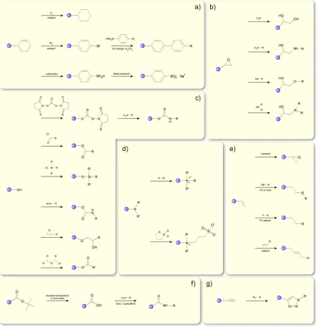
While the physical behavior of a polymer differs significantly from that of its building blocks, the chemistry available at the repeat units tends to be analogous to small-molecule reactions. Researchers have taken advantage of this point for decades, and a number of recent reviews summarize the options available to polymer chemists1,3,68–70. We will only highlight a few of the more common and versatile reactions here (cf. Figure 2.4).
Figure 2.4. Selected coupling reactions employed in PPM processes involving coupling of various functional groups with pendent: a) phenyls, b) epoxys, c) hydroxyls, d) tertiary amines, e) vinyls, f) t-butyls and amino acids, g) alkynes.
reaction68,69,76,77, and the related thiol-yne reaction77,78. Both of these reactions proceed to high conversions, and the ease of inserting these functional groups into polymers makes them very appealing. Furthermore, the fact these reactions do not require (typically) a catalyst makes those coupling reactions particularly useful for incorporating biological moieties in polymer chains.
Another class of reactions employed in post-polymerization modification involves the quaternization of tertiary amines to quaternary ammonium groups79. These reactions appear often in this review to produce cations of poly(2-dimethylaminoethyl methacrylate) (PDMAEMA) and poly(2-vinylpyridine) (P2VP) and poly(4-vinylpyridine) (P4VP) (see Section 2 ). A general scheme is shown in Figure 2.4. These reactions quickly proceed to high conversions, and can introduce a number of functional groups into the polymer at mild conditions without a catalyst, as well as produce polycations. Tertiary amines are also available for betainization, which produces zwitterionic pendant groups; that is the polymer has an overall neutral net charge, but possesses two sites of opposite charge on the same pendant group (cf. Figure 2.4d). Like quaternization, this reaction proceeds typically to high conversions under relatively mild reaction conditions.
Polymers that bear aryl groups, particularly phenyl rings, can be modified by a number of addition reactions, including halogenation80,81 and sulfonation82, the latter of which produces polyanions, as noted in Section 2. Brominated aryl-containing groups can subsequently undergo Suzuki coupling with boronic acids to produce biaryls, whose functionality is derived by the chemical nature of the boronic acid83,84.
In addition to the above examples, PPM reactions using isocyanate reactions85–87 fluorination88,89, active esters90,91, ring opening reactions92–94, and non-covalent interactions4 have appeared in the literature. Furthermore, reports of polymer modification using electrochemical reduction95, electron beams96,97 have been published. Finally, the emerging field of mechanical modification of polymers, in which PPM is enacted by pressure changes or sonication, among others, has started to receive attention98–101.
2.2
Stimuli Responsive Brushes
wettability) characteristics. While all these examples have produced notable results, here we will focus solely on pH responsive polymer brushes23,110–115, which tend to protonate or deprotonate (i.e., change chemically, which is in line with the spirit of this review) under varying pH conditions. These polymers become charged above or below a certain pH value (pKa), producing polyanions or polycations, respectively. When the pH is adjusted back below or above the pKa, respectively, the polymers return to their original neutral state. Polymers that undergo this type of reversible charge are called “weak” (or annealed) polyelectrolytes (WP). In contrast, polymers that possess permanent charge centers, regardless of the surrounding pH, are called “strong” (or quenched) polyelectrolytes (SP).
2.2.1 Weak Polyelectrolytes
The following examples are intended to introduce the reader to the behavior of weak polyelectrolytes. This section does not contain a comprehensive list of PPM reactions that lead to WPs. Instead, we have selected a few representative examples that illustrate the fundamental behavior of WPs and leave more recent and application-driven examples for a latter portion of this review.
An early report from Sidorenko et al compared116 a mixed polystyrene (PS) and P2VP with the analogous homopolymer brushes. The authors demonstrated that the P2VP homopolymer brush swelled when exposed to a 0.1 N HCl solution, resulting from protonation of the nitrogen atom, and reverted to its original state after exposure to an alkaline solution. After exposing a mixed brush comprising 50% PS and 50% P2VP to a 0.1 N HCl solution, the top layer of the brush was 95% P2VP as determined by water contact angle. The segregation of the P2VP monomers to the surface followed their protonation, leading to an increased hydrophilicity. Exposure to toluene resulted in a top layer composition of 95% PS, confirming the solvent effect.
anion. The Huck group has recently visualized this ionic strength effect directly using confocal microscopy for poly(methacryloyloxyethyl phosphate) (PMEP) brushes labeled with dye molecules via a PPM reaction120.
2.2.2 Strong Polyelectrolytes
Many weak polyelectrolytes can be converted to strong polyelectrolytes through PPM reactions. Common examples include P4VP brushes121 and PDMAEMA brushes quaternized with alkyl halides122, as well as poly(styrene sulfonate) brushes produced via saponification123 or sulfonation82, and PMAA brushes produced via a deprotection reaction124,125.
In the case of the P4VP brushes, Rühe and coworkers used a PPM reaction in these studies, which enabled the direct comparison of the same brush’s behavior before and after quaternization with ethyl bromide121 and methyl iodide126 (cf. Figure 2.5). In salt-free solutions quaternization leads to an increase in the film thickness due to the increase in molecular mass of the repeating units. Furthermore, incorporation of a permanent charge center in the polymer pendant groups results in a polymer brush whose thickness does not depend on grafting density in salt-free solutions, as seen in Figure 2.5. This so-called “osmotic brush” results from an increased osmotic pressure within the brush caused by the addition of counterions. Biesalski and Rühe also examined the effect of charge density and ionic strength by quaternizing poly(4VP-co-dimethylacrylamide) brushes127, finding a smooth transition between the swelling behavior of a polyelectrolyte and neutral brush.
Figure 2.5. (A) Schematic depiction of the increase in swollen thickness of a polymer brush in a good solvent after the conversion of the neutral brush into the charged species due to the introduction of electrostatic forces. (B) Brush thickness as a function of graft density for neutral and charged brushes. The experimental results agree well with the predicted scaling laws, which are indicated as lines in the figure (L~σ0.33
2.3
Selected case studies involving PPM on macromolecular grafts
Polymer brushes can modify substantially properties of surfaces to which they are anchored. Very thin (only a few nm), yet active layers make great candidates as surface-bound barriers, functional coatings, and many others. PPM of grafted chains enhances greatly the functionality of the parent homopolymer brush in that it alters the chemistry of the grafted chains and in some instances also the co-monomer distribution of the original and newly added monomers. The chemical composition of the PPM grafts can be tuned by varying the degree of “chemical coloring” by controlling the reaction conditions, as was mentioned before. Adjusting the co-monomer distribution can be achieved by either varying the solvent quality or by using substrates with different curvatures. In Figure 2.6 we demonstrate pictorially how varying the substrate geometry alters the distribution (and affects to some extent the degree of PPM) of the chemical modifiers along the grafted macromolecules.
2.3.1 Altering Wetting Behavior of Surfaces
The wettability of a surface can be tuned by an appropriate choice of the surface chemistry and surface topography. For example, hydrophobic surfaces are fabricated by introducing fluorinated compounds. Thin films of hydroxylated poly(styrene-b-isoprene) or poly(methyl methacrylate-b-2-hydroxyethylmethacrylate) modified at the pendant hydroxyl groups with perfluorinated ester or fluorinated urethane and carbonate moieties exhibited heightened hydrophobicity and oleophobicity compared to the unmodified parent polymer85. These properties stem from the characteristics of fluorinated compounds enriching the surface, as demonstrated by x-ray photoelectron spectroscopy (XPS). These substrates could be patterned using a laser beam to selectively degrade the fluorinated compounds resulting in selected regions of enriched hydrophobicity. Brantley, Jennings and coworkers reported on PPM of poly(2-hydroxyethylmethacrylate) (PHEMA) brushes by acylchloride-based fluorinated compounds20,136–138. Arifuzzaman and coworkers139 later extended the efforts of Brantley et al by performing a comprehensive study aimed at modifying PHEMA brushes with fluorinated agents bearing various chemical head-groups, including acylchlorides, anhydrides, and organosilanes. Attachment of organosilanes to PHEMA was previously studied by two other groups140,141.
In another example, brushes of poly-N-[(2,2-dimethyl-1,3-dioxolane)methyl]acrylamide (PDMDOMA), which displays LCST behavior, were altered chemically by hydrolyzing the dioxolane groups, resulting in modified wetting behavior (cf. Figure 2.7)142. The authors reported on the dependence of wettability on the degree of chemical modification of the parent polymer as well as the grafting density of the brushes on the surface.
Figure 2.8. (left panel) (a) Schematic procedure of surface-initiated photopolymerization of TMS-protected propargyl methacrylate, deprotection, and subsequent thiol-yne functionalization. (b) Schematic procedure for photopatterning “yne”-containing polymer brush surfaces with sequential thiol-yne reactions. (right panel) Condensation images of sequential thiol-yne micropatterned brushes showing water droplets selectively nucleating on the hydrophilic MPA areas: (a) MPA/DDT (square/bars), 300 mesh; (b) MPA/DDT (squares/bars), 2000 mesh; (c) inverse DDT/MPA (squares/bars), 300 mesh; (d) Sunlight MPA/DDT (squares/bars); (e) static water contact angle measurements showing pH responsive reversible wettability of MPA surfaces prepared outdoors in sunlight. Note: Color variations result from thin film interference under humid conditions. Reproduced with permission from the American Chemical Society78.
diblock brushes with PtBA144, as well as using a methacrylate monomer with photocleavable o-nitrobenzene derivatives145. In a similar vein, Hensarling et al have modified propargyl methacrylate brushes using thiols in a UV-modulated reaction78. By masking certain regions during a first modification (say, to introduce hydrophobic pendant groups), then backfilling in a second modification step with hydrophilic groups, wettability patterning could be achieved like that shown in Figure 2.8.
Several reports on using counterions in polyelectrolyte brushes to modify surface wettability have also appeared146,147. To this end, Huck and coworkers have demonstrated the ability to modify the wetting behavior of polyelectrolyte brushes simply by exchanging different ions into the brush148. In a polycationic brush, water contact angle measurements for various counter ions went as: PO4-3 = 19, Cl- = 35, SCN- = 65, ClO4- = 79 degrees (cf. Figure 2.9). Similar results have been reported for polyanion brushes149. Furthermore, reduction of ferricyandide ions in a quaternized PDMAEMA brush using cyclic voltammetry led to similar control over the wetting angle150.
The Locklin group has also used counterions to control wetting behavior in polymer brushes containing spiropyran moieties151,152. Upon exposure to UV light in salt solutions, the pendant spiropyran groups rearrange and form organometallic complexes. In line with the aforementioned work by the Huck group, different counterions yield different water contact angles, though the spiropyran system reverts back to its original water contact angle upon exposure to light wavelengths in excess of 500 nm. Importantly, the various counterions also produced different color changes in the brush, suggesting these compounds hold promise as metallic ion sensors.
2.3.2 Ion Transport Barriers
The Jennings group has explored ion transport through fluorinated brushes thoroughly136,137; the researchers established that -CF3 groups decorating PHEMA brushes and enriched the surface after 25% conversion. The authors employed electrochemical impedance spectroscopy (EIS) to monitor ion transport and noted that resistance increased sharply up to 25% conversion of the HEMA units before leveling off. While this finding demonstrated how important the top few nanometers of a surface are to the properties of a substrate, impedance decreased rapidly until 60% conversion, indicating that the entire brush plays a role in governing ion barrier properties. In a similar examination, Brantley et al illustrated138 a method to modify reversibly PHEMA brushes modified with pentafluorobenzoyl chloride (FBZ). A basic solution hydrolyzes the ester linkages formed by FBZ, recovering the original PHEMA brush. By taking advantage of diffusion, the authors tuned the thickness of the FBZ layer, then modified the recovered PHEMA brush with a second moiety, including alkyl and fluoroalkyl chains, or FBZ. The hydrophobicity and resistance of the film increased as F7/FBZ > H7/FBZ > FBZ/FBZ > PHEMA/FBZ.