Selvam College of Technology, Namakkal, Tamilnadu, India
Analysis of Tube Failure in Water Tube boiler
P.Sakthivel1, S.Kalaimani2, Dr. R. Sasikumar3
PG Scholar, Department of Mechanical Engineering, Selvam College of Technology-Namakkal. Tamilnadu, India1,
Associative Professor, Department of Mechanical Engineering, Selvam College of Technology-Namakkal.
Tamilnadu, India2
Dean/ Research & Development, Department of Mechanical Engineering, Selvam College of Technology,
Namakkal, India. 3
ABSTRACT: Boiler tube failure continues to be the leading cause for forced outages in fossil fired boiler. The tube failure may be a simple problem unless it causes damage to the power plant and affects safety of the human being. The problem due to tube failure is realized only when the cost due to failure estimated. The main objective of our project is to reduce the number of tube failures occurring in boiler accessories at thermal power station by analyzing the reason behind the tube failure and provide suitable remedies for it. Tube failures in boiler accessories occur due to various reasons and major reasons for failure among the various reasons are flue gas erosion, long term overheating and steam erosion. The major failure reasons are taken from the tube failure. Major causes for failure can be controlled by using following remedies such as optimization of flue gas velocity, using tube material with better creep strength and by providing coating along the wall of the tube. The optimization of flue gas velocity is done by computational fluid dynamics software (Ansys fluent), the boiler tube material is chosen based on the cost , creep strength and corrosion resistance, the coating for boiler tube is chosen based on operating conditions and coating feasibility. The above remedies if implemented in the power plants can reduce the tube failure to a major extent.
I. INTRODUCTION
A. General
In this chapter we are going to discuss about Tube failures in boiler accessories occur due to various reasons and major reasons for failure among the various reasons are flue gas erosion, long term overheating and steam erosion. The major failure reasons are taken from the tube failure. Major causes for failure can be controlled by using following remedies such as optimization of flue gas velocity, using tube material with better creep strength and by providing coating along the wall of the tube.
B. Boiler:
A boiler is an enclosed vessel that provides a means for combustion heat to be transferred in to water until it becomes heated water or steam. The hot water or steam under pressure is then usable for transferring heat to a process. Water is a useful and cheap medium for transferring heat to a process a force that is almost as explosive as gunpowder. This causes the boiler to be extremely dangerous equipment that must be treated utmost care. The process of heating a liquid until it reaches its gaseous state is called evaporation. Heat is transferred from one body to another by means of 1) Radiation, which is transfer of heat from hot body to cold body without a conveying medium,
2) Convection transfer heat by a conveying medium, such as air or water 3) Conduction, transfer heat by actual physical contact, molecule to molecule.
1.1 Water Tube Boiler
Selvam College of Technology, Namakkal, Tamilnadu, India
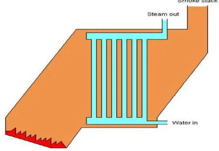
In some services, the steam will reenter the furnace through a super heater to become superheated. Cool water at the bottom of the steam drum returns to the feed water drum via large-bore ‘down comer tubes’, where it pre-heats the feed water supply. To increase economy of the boiler, exhaust gases are also used to pre-heat the air blown into the furnace and warm the feed water supply. Such water tube boilers in thermal power station are also called steam generating units. Fig 1.1 shows the schematic representation of a simple water tube boiler.
Fig. 1.1simple water tube boiler
1.2 Boiler Tube
Boiler tubes are set of long goes several folds inside the furnace, sometimes their total length may be several kilometers mainly in the case of power plant boilers, and these tubes transfer heat from flue gas to water or steam. Fig 1.2 shows tubes of a typical water tube boiler in a power plant
Table 1.1 shows the specification of economizer tubes in water tube boiler of Thermal power station.
Fig. 1.2 Tubes of a water tube boiler
Tube material SA210GrA1(C=0.27%)
Tube diameter 44.5 mm
Tube thickness 4.5 mm
Tube length 32 km(approx)
No of bends 14
Tube arrangement Horizontal
Tube bend diameter 65 mm
Selvam College of Technology, Namakkal, Tamilnadu, India
II. CAUSES OF TUBE FAILURE
This chapter explains about problems in boiler tubes and the factors that cause major damage to the boiler tubes. This helped to identify the major reasons for tube failures and suggest suitable remedies for the failures caused due to the problems.
2.1 Types of failure
Failures in the boiler tubes occur at various places corresponding to the parameter causing the defect. Below listed are such failures which could be seen in boiler tubes
• Fish mouth opening
• Window opening
• Burst open puncture • Pin hole puncture • Crack formation
2.2 Areas of failure
Most of the failures in the boiler happen at repeated places. Places at which tube failures seen most are Economizer, Extended steam cooled tubes, Water walls, LTSH, Reheater tubes, Platen super heater and Final super heater. All these places require very good maintenance for longer life and to reduce the failure rate occurring in it.
2.3 Causes of Tube Failure
There are numerous that accounts to the failure of boiler tube in water tube boilers. There are twenty-two primary reasons for tube failures in a boiler. Knowledge and good operating and maintenance practice reduce tube failures. Reducing tube failure in boilers increases the availability of boiler.
A single tube failure in boiler may cause loss of millions of rupees apart from power loss. There are four major groups into which all tube failures can be classified. Tube failures are classified as in-service failures and can be grouped under four major causes:
• Erosion • Stress rupture
• Corrosion • Loss of quality
2.3.1 Erosion
There are various reasons behind the erosion of boiler like fly ash, coal particles etc. The factors that which causes erosion in boiler tubes are listed below
• Fly ash • Coal particles
• Falling slag • Air erosion
2.3.1.1 Fly ash
Fly ash travels with the flue gas at the same speed around 11m/s when it continuously travels at this speed it would erode the metal in constant manner and finally it would reaches the critical limit at which the tube could no more with stand the pressure.
The amount of ash in coal and its velocity are major factors in the rate of fly ash erosion.fly ash erosion is experienced in the economizer, primary SH, and inlet section of steam reheater tubes. When non-uniform flue gas flow distribution occurs in these areas, the rate of erosion increases multifold.
Factors influencing fly ash erosion in coal fired boilers are • The velocity of flue gas
• The temperature of flue gas • The mineral content in coal • The change in direction of flue gas • The arrangement of pressure parts and
Selvam College of Technology, Namakkal, Tamilnadu, India
2.3.1.2 Coal particles
Coal particle erosion is to similar to Fly ash particles erosion in which unburnt coal particles flew with the Flue gas erodes the boiler tube material, it may also deposit on the tube surfaces and cause reduced heat transfer and corrosion. The following are the areas in boiler where coal particle erosion is normally experienced Economizer bends and tubes, Screen tubes, Goose neck portion at furnace top, Soot blower opening in the water walls, Wind box opening in the furnace, Bottom hoper tubes. Fig. 2.3 represents the boiler tube erosion due to coal particles.
Fig. 2.3 Coal particle erosion
2.3.1.3 Slag formation
Slag is formed by the reaction of deposited ash particles with the boiler tube material, prolonged traveling of ash particles around boiler tube cause deposition of ash and at high temperature these ash deposit and boiler tube particle reacts to form molten metal slag , this falls on the lower tube and erodes those tubes. Fig. 2.4. represents the formation of slag around boiler tubes.
Fig. 2.4. Slag formed around boiler tubes
2.3.1.4 Air erosion
Continuous flow of hot air in the flue gas also cause a considerable erosion, but when compared to other factors which is causing the erosion it is bit lower.
2.3.2 Stress rupture
Stress rupture is another important cause to the failure of boiler tubes in water tube boilers. Some reasons for the stress rupture of boilers are given below
• Long term over heating
• Short term over heating
• Dissimilar metal welding
2.3.2.1 Short term over heating
Selvam College of Technology, Namakkal, Tamilnadu, India
cooling from water flow inside and receives excessive heat input from combustion process will lead to short term overheating. Fig. 2.5 shows the boiler tube failed due to short term overheating.
Fig. 2.5 Short term over heating
2.3.2.2 Long term over heating
Long term overheating tube failures are due to metal temperature of the boiler tubes going above the allowable limit. These types of failure are seen in steam cooled tubes like super heaters and re-heaters and in water cooled tubes of water walls. While selecting the tube there is a requirement to select the correct material for withstanding the metal temperature.
Normally the water cooled areas like economizer and water walls are made of carbon steel of boiler quality. Super heaters and re-heaters will have combination of low alloy tubes to stainless steel tubes selected to with stand the metal temperature. Fig. 2.6 shows the failure of boiler tube due to long term overheating.
Fig. 2.6 long term overheating
2.3.2.3 Dissimilar metal welding
In the thermal power station, dissimilar metal welds (DMWs) are used to join ferritic low-alloy steels to austenitic stainless steels. Unfortunately, these welds can fail prematurely from accelerated creep. However, a transition joint where the composition changes from austenitic steel to ferritic steel could replace then one dissimilar weld with two similar welds. Fig. 2.7 shows the failure of dissimilar metal welds in boiler tube of a water tube boiler
Selvam College of Technology, Namakkal, Tamilnadu, India
2.3.3 Corrosion
In corrosion boiler tubes materials are taken away by chemicals around it. Some of reasons behind corrosion are listed below
• Caustic corrosion • Pitting corrosion
• High temperature corrosion
• Low temperature corrosion
2.3.3.1 Caustic corrosion
Caustic corrosion, a specific form of stress corrosion, results in the inter crystalline cracking of steel. Inert crystalline cracking results only when all of the following are present: specific conditions of stress, a mechanism for concentration such as leakage, and free NaOH in the boiler water. Therefore, boiler tubes fail from caustic embrittlement at points where tubes are rolled into sheets, drums or headers. Fig.2.8 shows the boiler tubes attacked by caustic corrosion.
Fig.2.8 Caustic corrosion
2.3.3.2 Pitting corrosion
Fig.2.9 Pitting corrosion
Pitting corrosion is a form of extremely localized corrosion that leads to the creation of small holes in the metal. The driving power for pitting corrosion is the depassivation of a small area, which becomes cathodic; leading to very localized galvanic corrosion. The corrosion penetrates the mass of the metal, with limited diffusion of ions. Fig. 2.9 shows the pitting corrosion in a tube of water tube boiler.
2.3.3.3 High temperature corrosion
Selvam College of Technology, Namakkal, Tamilnadu, India
include high temperature oxidation, sulfidation and carbonization. Fig. 2.10 shows the damaged boiler tube due to high temperature corrosion.
Fig. 2.10 High temperature corrosion
2.3.3.4 Low temperature corrosion
Thermal power station uses coal as a fuel, this fuel contains sulpher to differing percentages. The higher the percentage of sulpher, the higher will be the risk of cold and corrosion in the boiler.
The sulpher in thr fuel during combustion gets converted to sulpher dioxide, some portion of the sulpher dioxide gets converted to sulpher trioxide. The presence of moisture in the flue gas due to moisture in the fuel and air, sulpher dioxide, and trioxide, combines with moisture and forms sulphuric acid.
These acids condense from around 1150C to slightly higher than 1600C, depending upon the concentration of SO3 and water- vapour. Condensation of these acids results in metal wastage and boiler tube failure, air preheater
corrosion, and flue gas duct corrosion.
III FAILURE AND REMEDIES
This chapter deals with the detailed analysis of boiler tubes and also tells about the various solutions to reduce most commonly occurring tube failure.
3.1 Remedies of tube failure
From the failure data and analysis using pie chart the three major erosion causing factors are flue gas erosion, long term overheating and steam erosion. Our concentrates on giving remedies to these three problems. The type of failure and chosen remedies are shown in table 3.1
Table 3.1 Remedies for tube failure
S.No Type of Failure Remedies
1 Flue gas erosion Organization of flue
gas velocity
2 Long term over heating Changing the tube
metal
3 Steam erosion Protective coating
3.2 Detail of software for used for Ansys
• Software Name : Ansys
Selvam College of Technology, Namakkal, Tamilnadu, India
3.3.1 Details needed for software
Water temperature at inlet of economizer :520k
Water temperature at outlet of economizer :557k
Flue gas temperature at inlet of economizer :752k
Flue gas temperature at outlet of economizer :660k
Type of flow : counter flow
Flue gas velocity : 11 m/s
3.3.2 Boundary condition for analysis 1. Water inlet
Table3.2 shows the boundary conditions water inlet of the economizer
Table 3.2 Boundary conditions for water inlet
S.No Parameters value
1 Mass flow rate 0.132 m/s
2 Velocity 8 m/s
3 Temperature 520 k
2. Water outlet
Table3.3 shows the boundary conditions for water outlet of the economizer
Table 3.3Boundary conditions for water outlet
S.No Parameters Value
1 Outflow Nil
2 Temperature 552 k
3. Flue gas inlet
Table3.4 shows the boundary conditions for flue gas inlet
Table3.4 Boundary conditions for flue gas inlet
S.No Parameter value
1 Mass flow rate 0.126 kg/s
2 Velocity 11 m/s
3 Temperature 752 k
4. Flue gas outlet
Table 3.5 shows boundary conditions for flue gas outlet
Table 3.5 Boundary conditions for flue gas outlet
S.No Parameters Value
1 Outflow Nil
2 Temperature 660 k
3.4 Erosion rate calculation for tube
E = (0.47×z4.95 ×ρm×ρp×v3×sin3β)/σy1.5
Where
Selvam College of Technology, Namakkal, Tamilnadu, India
ρ'p =Density of ash particles kg/m3
β =impingement angle (degrees) σy = yield stress of steel (N/m2)
V = Flue gas velocity (m/s) On substituting the values,
E=0.47x0.016x7830x34.64x1331x0.125/(250x106) E=0.182(mg (steel)/kg (ash))
Similarity for calculating to other velocities Table 3.6 shows the erosion rate for various velocities.
Table 3.6 calculated Erosion rate for various velocities
Flue gas velocity Erosion rate (mg/kg)
8 0.07
9 0.1
10 0.137
11 0.182
12 0.237
13 0.301
Table 3.7 shows the outlet temperature for various velocities.
Table 3.7 Outlet temperature for various velocities
S.No Velocity in (m/s) Temperature at outlet (k)
1 8 356
2 9 359
3 10 361
4 11 363
5 12 365
6 13 367
By comparing the minimum temperature at outlet from CFD results and Erosion rate the optimum flue gas velocity is 9m/sec.
3.5 Material for boiler tubes
Generally boiler materials need to with stand high temperature and should not corrode easily. The boiler materials should have high creep strength and corrosion resistance. The table 3.8 shows the various materials form boilers tubes which with stand high temperature and have good corrosion properties.
Table 3.8 various materials for boiler tubes
S,No Material Maximum withstanding
temperature(°C)
1 T91 600
2 S 304 H 645
3 HR 3C 675
4 SANICRO 25 700
5 ALLOY 617 770
3.6 Materials under usage for boiler tubes
Austenitic stainless steel is the material that is currently being used for boiler tubes in thermal power plant.Major reasons for using stainless steel are
Resistance to corrosion
Selvam College of Technology, Namakkal, Tamilnadu, India
Resistance to oxidation
Ease of fabrication
Excellent formability
Good strength and toughness at cryogenic temperatures table 3.9 shows the composition of austenitic stainless steel.
Table 3.9 composition of austenitic stainless steel
Material Type 304 Type 304L
Carbon 0.08 max 0.08 max
Manganese 2.00 max 2.00 max
Phosphorus 2.00 max 2.00 max
Sulfur 0.030 max 0.030 max
Silicon 0.75 max 0.75 max
Chromium 18.00-20.00 18.00-20.00
Nickel 8.0-12.00 8.0-12.00
Nitrogen 0.10 max 0.10 max
Iron Balance Balance
3.6.1 Mechanical properties
Table 3.10 shows Mechanical properties of austenitic steel
Table 3.10 Mechanical properties of austenitic steel
Type Ultimate tensile
strength (MPa)
Yield strength (MPa)
Elongation
% Hardness Rockwell
304L 586 241 55 B80
304 621 290 55 B82
3.6.2 Physical properties
Density : 7.90 g/cm3
3.6.3 Thermal properties
The thermal conductivity, coefficient of thermal expansion of stainless steel are shown in table 3.11 and 3.12 respectively.
Table 3.11 Linear coefficient of thermal expansion of steel
Temperature Range coefficients
˚F °C in/in/˚F cm/cm/°C
68-212 20-100 9.2×10⁻⁶ 16.6×10⁻⁶
18-1600 20-870 11.0×10⁻⁶ 19.8×10⁻⁶
Table 3.12 Thermal conductivity of steel
Temperature range
W/m k
˚F ˚C
212 100 16.3
Selvam College of Technology, Namakkal, Tamilnadu, India
3.6.4 Suggested material –SANICRO 25
Sanicro 25 is a high alloy austenitic stainless steel engineered for the next generation of coal –fired power boilers. It is ideal for reheater and super heater tubes, allowing for material temperatures of up to 700˚c (1290˚F), significantly greater efficiency and sharply lower CO2.
Very high creep strength
High oxidation resistance
High structural stability
Good fabric ability
Sanicro 25 is supplied as cold pilgered solution annealed and white – pickled or bright annealed seamless tubes, in common reheater and super heater boiler tube dimensions. The material datasheet 555 is valid for outside diameter 25 mm to 114.3 mm and wall thickness 3 mm to 14 mm.
Very high elevated temperature strength
Precipitation strengthening
Nb or NbCr nitrides, Cu- rich precipitates
Solid solution strengthening: addition of C, N, Co and W
High corrosion resistance at high temperature
High structural stability $ good fabricability
3.6.5 Composition of sanicro 25
Table 3.13 shows the composition of sanicro 25 alloy
Table 3.13 composition of sanicro 25
Material Percentage
Cmax 0.1
Si 0.2
Mn 0.5
Pmax 0.030
Smax 0.015
C 22.2
Ni 25
N 0.23
W 3.6
Co 1.5
Cu 3.0
Nb 0.5
3.6.6 Mechanical properties
Table 3.14 shows the mechanical properties of sanicro 25 alloy
Table 3.14 mechanical properties of sanicro 25
Temperature ˚C
Proof strength MPa
Tensile strength MPa
600 205 500
700 195 455
3.6.7 Physical properties
Density: 8.1 g/cm3
3.6.8 Thermal properties
Selvam College of Technology, Namakkal, Tamilnadu, India
Table 3.15 thermal expansion
Temperature per°c
30-500 16.5
30-600 16.5
30-700 17
30-800 17
30-900 17.5
Table 3.16 thermal conductivity
Temperature W/(m˚c)
500 20
600 22
700 23
800 25
900 27
3.6.9 Comparison between austenitic stainless steel & sanicro 25
Table 3.17 compares austenitic stainless steel & sanicro 25
Table 3.17 Steel vs Sanicro 25
Property Sa 210 gr A1 Sanicro 25
Density 7850 kg/m3 8100 kg/ m3
Coefficient of thermal expansion 18.8 19
Yield strength 260n/mm2 140n/mm2
Tensile strength 420 n/mm2 340n/mm2
Thermal conductivity 21.4 22.5
Creep strength(at 600°c) 120 n/mm2 230n/mm2
Fig. 3.2 Meshing diagram of tube
Fig. 3.3 Temperature Distribution of Sanicro25
3.8 Coating for boiler tubes
Selvam College of Technology, Namakkal, Tamilnadu, India
3.9 Coating materials
There are various materials used for coating the boiler tube for protection against various causes that account for the tube failures like Erosion, corrosion etc..,the materials used in boiler tube coating are
• M-Cr-Al-y alloy
• Type 310 stainless steel
• Pure chromium
• Molybdenum
• High silicon alloy
• Ni/Cr alloys
• Molybdenum
• Fe-Al
3.9.1 M-Cr-Al-y alloy
The M of stands for either Ni or Co or a combination of both (when applied to steels it can also be Fe) depending on the type of super alloy.co based appear to have superior resistance to corrosion.
Al content is typically around 10-12 wt%. Since oxidation life is essentially controlled by the availability of al it would be tempting to increases the aluminum content. However these results in significant reduction of ductility also typically contain 1 wt% yttrium which enhances adherence of the oxide layer.
3.9.2 Type 310stainless steel
Type 310 alloys is essentially the stainless steel with more corrosion and temperature resistance it could with stand the temperature up to 1100c and it also resists the chemical corrosion by means of formation of thin chromium oxide layer over it and it also saves the boiler tube by means of self sacrificing.
It contains iron as its main content and other major contributoes are Nickel and chromium both its contributes about 15-22% each and other minor contributors are carbon (1.5%), Manganese(2.0%), phosphorous(0.04%)and sulphur(0.03%). This alloy has the density of 8000kg/m3 melting point of 1500c specific heat capacity of 500J/kgc thermal conductivity of 14.2W/m and coefficient of expansion of 15.9/c.
3.9.3 Pure chromium
Pure chromium can be deposited on the boiler tube by means of Electro deposition method as this method could evenly deposit the chromium over its surface this coating could only be done on the shop could not be done inside the boiler this is the main disadvantage of this coating.
This pure chromium coating protects the boiler tube corrosion by forming thin oxide layer over itself on initial operation of boiler after coating surface chromium reacts with oxygen and forms thin protective coating of chromium oxide over its surface to resist the chemical corrosion it also resists the erosion by self sacrificing it distributes the heat evenly over the boiler tube and thus it reduces the fatigue.
3.9.4 Ni/Cr Alloys
Chromium is a corrosion resistant alloy that binds the continuous skeleton of erosion resistant chromium carbide constituents. Due ability to dissipate the impact force of particles by plasticide formation result of Ni-Cr coatings are
High hardness (to prevent erosion because of ash silica).
Hot corrosion resistance (that will react with the environment to produce a slow growing protective oxide scale which should not allow the corrosive pieces to diffuse into the coating)
Low porosity (less area for erodent particle to impact and abrade ).
Small grain size (Small grains tend to be stronger).
Uniform coating structure (homogeneous distribution of hard constituents & ductile behaviour )
Absence of cracks (ductile structure, thermal stability,Uniform coating structure (homogenous distribution of hard constituents &ductile behaviour)
Selvam College of Technology, Namakkal, Tamilnadu, India
3.9.5 Iron aluminide
Iron-aluminium based alloys have been considered as coating for the protection of water wall boiler tubes found in coal-fired furnaces. These iron-aluminium based alloys are potentially good candidates for boiler tube coatings because they have excellent corrosion resistance in a wide range of high temperature gaseous environments including highly sulfidizing environments.
These coatings are advantageous over commercial alloys such as stainless steels and ni-based super alloys, because they are significantly less expensive than the commercial alloy , they do not experience micro segregation as seen in the ni-based super alloys and they do not from a brittle interface at the fusion zone as seen in some stainless steel weld overlays.
Studies have shown that increasing the aluminium content of fe-al based alloy increases the corrosion resistance of the alloy in high temperature environments containing oxygen and sulphur 2,4,5,8.
3.10 methods of coating
The various methods employed in coating are:
Electrodeposited inter metallic coatings
Weld overlay coatings
Thermal sprays coatings
3.10.1 Electro deposited inter metallic coatings
Fig. 3.4 shows a boiler tube sample coated by electrodeposited inter metallic coatings
Fig. 3.4 Electro deposited inter metallic coatings
Selvam College of Technology, Namakkal, Tamilnadu, India
3.10.2 Weld overlay coatings
Fig 3.5 shows the boiler surface coating with weld overlay coating .
Fig. 3.5 weld overlay coating
The advantage of welded coatings is that they can be applied to the surface of the boiler tubes in the boiler as well as in a shop, without the usual penalties. However, selection proper weld alloy and control of the weld overlay process conditions are critical to producing coatings with desired properties.
3.10.3 Thermal spray coatings
Fig 3.6 shows the thermal spray coating equipment
In the application of thermal spray coating, a metal powder is a heated to a high temperature and propelled toward the boiler tube surface with a high velocity gas or plasma jet. Once at a surface, the particles from a coating. Thermal spray coating have a advantage of being applied in- situ in the boiler and as a consequence, they are easily repaired after exposure.
Fig. 3.6 thermal spray coating
IV CONCLUSION
Selvam College of Technology, Namakkal, Tamilnadu, India
9m/sec which would considerably reduced tube failure due to flue gas erosion. The usage of sanicro 25 as tube material for boiler tubes provides extended tube life due to its better creep strength and this reduces the failure rate due to long term over heating in boiler tubes. The loss power production and the cost of repair for boiler tubes can be reduced. Failure due to steam erosion is reduced if coatings such as electro deposited inter metallic coating, weld overlay coating and thermal spray coating are applied on the boiler tube surface. The above remedies if implemented in power plants not only reduced tube failure, but also reduce the repair cost of tubes, increase the availability of boiler, less interruption in power generation. The general suggestion to reduced tube failure is to use low as coal which will reduced erosion rate and also reduced the major tube failure problems. The future presents several challenges, with expected tightening electricity market likely to increase the cost of boiler tube failure coming at a time when number of failures is expected to rise.
REFERENCES
1. GOPALAKRISHNA (2003) “Phosphate induced stress corrosion cracking in a water wall tube from a coal fired boiler” Engineering failure analysis, volume no 10.
2. M.R. KHAJAVI (2006) “Failure analysis of bank front boiler tubes” Engineering failure analysis, volume no 14.
3. KHALIL RANJBAR (2006) “Failure analysis of boiler cold and hot reheater tubes” Engineering failure analysis, volume no 14. 4. MASOUD RAHIMI (2006) “CFD modeling of boilers tubes’s tubes ruptures” Applied thermal engineering, volume no 26.