ISSN(Online): 2319-8753
ISSN (Print): 2347-6710
I
nternational
J
ournal of
I
nnovative
R
esearch in
S
cience,
E
ngineering and
T
echnology
(An ISO 3297: 2007 Certified Organization)Vol. 6, Special Issue 11, May 2017
Deep Beam Analysis Using FEM Program and
ANSYS for ISO-parametric elements
Umesh Wani1, Prof. Sanjay Bhadke2
PG Student, Department of Civil Engineering, Tulsiramji Gaikwad-Patil College of Engineering & Technology, Nagpur, India1
Assistance Professor, Department of Civil Engineering, Tulsiramji Gaikwad-Patil College of Engineering & Technology, Nagpur, India2
ABSTRACT: The structural bending members can be broadly divided into two regions. The first region is the Bernoulli regions (B- regions) , where the strain distribution is linear There are several analytical tools available for analyzing of a deep beam . It is recognized that the distribution of the strain across the section of deep beams is nonlinear and hence, these structural elements belong to the D-Regions. Traditionally, the D-Regions have been designed using empirical formulae or past experience. Recently, the Strut-and-Tie Model (STM) has been recognized as an effective tool for design of both B-and D- Regions but still method has not yet been widely implemented. There are various theories which consider the shear deformation effect, developed by the researchers for the analysis of deep beams. These theories have their own assumptions and limitations.
There are many software packages available for the analysis of deep beams but we generally use SAP, ANSYS software. In finite element method many isoparametric elements are available such as triangular element, elements of serendipity family. In ANSYS it is modeled using Solid82 for 2D analysis.
In this project, results of deflection, flexural stress and shear stress of cantilever prismatic deep beams obtained using FEM program for isoparametric elements, and ANSYS 2D analysis are compared. A parametric study of deep rectangular beams for point load has been carried out.
KEYWORDS: Deep beam, aspect ratio, convergence study, discritisation, flexural stress
I. INTRODUCTION
Deep beams are defined as the members loaded on one face and supported on the opposite face so that compression struts can develop between the loads and the supports. In IS-456 (2000) clause 29, It is a fact that in the finite element analysis, as the number of elements increases the result comes closer to the true results. Continuous beams are considered as deep when the ratio L/D is less than 2.5. The effective span is defined as the center to center distance between the supports or 1.15 times the clear span whichever is less.
The use of reinforced concrete deep beam has become more prevalent in recent years. Deep beams often appear in form of transfer girders in high rise building as well as pile caps, foundation walls, water tanks, bins, folded plate roof structures, floor diaphragms, shear walls & brackets or corbels.
ISSN(Online): 2319-8753
ISSN (Print): 2347-6710
I
nternational
J
ournal of
I
nnovative
R
esearch in
S
cience,
E
ngineering and
T
echnology
(An ISO 3297: 2007 Certified Organization)Vol. 6, Special Issue 11, May 2017
II. ANALYSIS OF BEEP BEAM
Analysis of deep rectangular beam subjected to point load.Comparative study of deep beams of various aspect ratios using FEM.Comparisons of the results obtained from FEM Program for isoparametric elements, and ANSYS 2D analysis
III.DETAILS OF DEEP BEAM
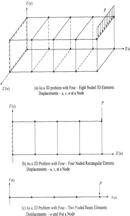
A cantilever beam with rectangular cross section (b × h) is subjected to concentrated load P at free end i.e. at x = L at surface z = −h/2 acting in the z direction. The origin of the beam is taken at fixed end i.e. at x = 0. The boundary
conditions associated with cantilever beam are as given:
ISSN(Online): 2319-8753
ISSN (Print): 2347-6710
I
nternational
J
ournal of
I
nnovative
R
esearch in
S
cience,
E
ngineering and
T
echnology
(An ISO 3297: 2007 Certified Organization)Vol. 6, Special Issue 11, May 2017
IV. ANALYTICAL RESULTS
The common type of isoparametric elements used for 2D elastic analysis are linear, parabolic (quadratic) and cubic elements with 4,8 and 12 nodes respectively. Thus, we have
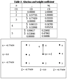
Table 1: Abscissa and weight coefficient
n
iw
i(1) (2) (3) 1 0.00000 2.00000 2
0.57735 1.00000 3
0.774590.00000
0.55555 0.88888 4
0.86113
0.339980.34785 0.65214 5
0.90617
0.53846 0.000000.23692 0.47862 0.56886
Figure. 2: Figure 4.4: Location of points in the ξ – η plane for the element
ISSN(Online): 2319-8753
ISSN (Print): 2347-6710
I
nternational
J
ournal of
I
nnovative
R
esearch in
S
cience,
E
ngineering and
T
echnology
(An ISO 3297: 2007 Certified Organization)Vol. 6, Special Issue 11, May 2017
ANSYS:
ANSYS software is a powerful and flexible general-purpose finite element analysis and computational fluid dynamics package used for civil engineering. Mechanical engineering, electrical engineering, physis and chemistry simulations. Simulation tools including ANSYS Mechanical APDL,ANSYS CFX and ANSYS FLUENT, can also solve mechanical problems, static/dynamic structural analysis, heat transfer and fluid problem as well as acoustic and electromagnetic problems.
Figure4: PLANE82 Geometry
PLANE82 Input Summary Nodes
I, J, K, L, M, N, O, P
Degrees of Freedom
UX, UY
Real Constants
None, if KEYOPT (3) = 0, 1, or 2 THK - Thickness, if KEYOPT (3) = 3
Material Properties
EX, EY, EZ, PRXY, PRYZ, PRXZ (or NUXY, NUYZ, NUXZ),
ALPX, ALPY, ALPZ (or CTEX, CTEY, CTEZ or THSX, THSY, THSZ), DENS, GXY, DAMP
Surface Loads Pressures --
face 1 (J-I), face 2 (K-J), face 3 (I-K), face 4 (I-L)
Body Loads Temperatures --
T(I), T(J), T(K), T(L), T(M), T(N), T(O), T(P)
Fluences --
FL(I), FL(J), FL(K), FL(L), FL(M), FL(N), FL(O), FL(P)
PLANE82 Output Data
The solution output associated with the element is in two forms:
Nodal displacements included in the overall nodal solution
Additional element output
ISSN(Online): 2319-8753
ISSN (Print): 2347-6710
I
nternational
J
ournal of
I
nnovative
R
esearch in
S
cience,
E
ngineering and
T
echnology
(An ISO 3297: 2007 Certified Organization)Vol. 6, Special Issue 11, May 2017
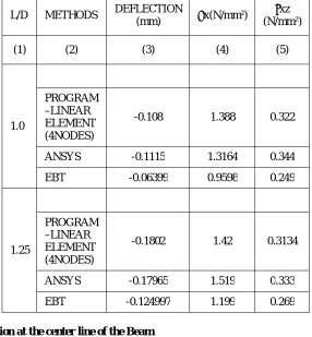
Table 2 : Results of displacement and stresses for various L/D ratios
L/D METHODS DEFLECTION
(mm) σx(N/mm²)
τxz (N/mm²) (1) (2) (3) (4) (5)
1.0
PROGRAM –LINEAR ELEMENT (4NODES)
-0.108 1.388 0.322
ANSYS -0.1115 1.3164 0.344 EBT -0.06399 0.9598 0.249
1.25
PROGRAM –LINEAR ELEMENT (4NODES)
-0.1802 1.42 0.3134
ANSYS -0.17965 1.519 0.333 EBT -0.124997 1.199 0.269
Graph showing deflection at the center line of the Beam
ISSN(Online): 2319-8753
ISSN (Print): 2347-6710
I
nternational
J
ournal of
I
nnovative
R
esearch in
S
cience,
E
ngineering and
T
echnology
(An ISO 3297: 2007 Certified Organization)Vol. 6, Special Issue 11, May 2017
Graph showing deflection at the center line of the Beam
Figure7: Deflection curve for L/D=1.25
Variation of Flexural Stress near the Support of the Beam
………….
Program 4 nodes
…………. EBT
…………..
Ansys………….
Program 4 node
ISSN(Online): 2319-8753
ISSN (Print): 2347-6710
I
nternational
J
ournal of
I
nnovative
R
esearch in
S
cience,
E
ngineering and
T
echnology
(An ISO 3297: 2007 Certified Organization)Vol. 6, Special Issue 11, May 2017
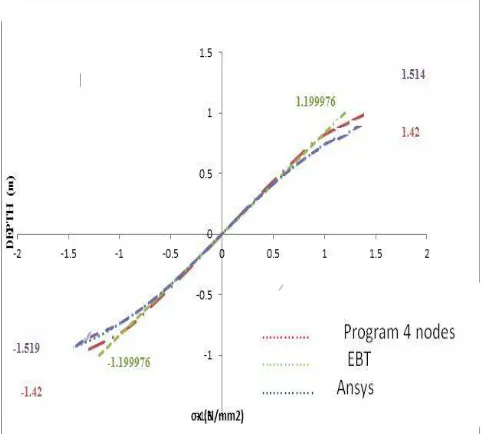
Variation of Flexural Stress near the Support of the Beam
Figure 8: Flexural Stress curve for L/D=1.25
Variation of Shear Stress at the Mid-Span of the Beam
Figure 9: Shear Stress for curve for L/D=1
………….
Program 4 nodes…………. EBT
ISSN(Online): 2319-8753
ISSN (Print): 2347-6710
I
nternational
J
ournal of
I
nnovative
R
esearch in
S
cience,
E
ngineering and
T
echnology
(An ISO 3297: 2007 Certified Organization)Vol. 6, Special Issue 11, May 2017
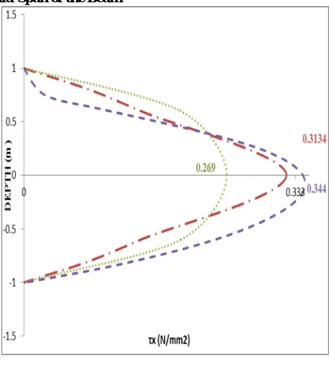
Variation of Shear Stress at the Mid-Span of the Beam
Figure 10: Shear Stress for curve for L/D=1.25
ANSYS SCREENSHOT SHOWING FINAL SOLUTION
…………
Program 4 nodes………….
EBT
ISSN(Online): 2319-8753
ISSN (Print): 2347-6710
I
nternational
J
ournal of
I
nnovative
R
esearch in
S
cience,
E
ngineering and
T
echnology
(An ISO 3297: 2007 Certified Organization)Vol. 6, Special Issue 11, May 2017
III. CONCLUSION
Deflection values given by EBT are much less than the values given by FEM program and ANSYS in case of rectangular deep beam.From the results given by FEM program, ANSYS it is found that the flexural stress distribution in deep beam is not linear as in case of slender beams, but EBT gives the flexural stress distribution as linear for deep beam.EBT gives the maximum shear stress at the centre line of the beam, but in deep beams the maximum shear stress is below the centre line of the beam.It is observed that the neutral axis moves downward.It is observed that though there is a variation in the results of deflection obtained from FEM Program and ANSYS, the agreement is very close.
REFERENCES
1. Wasulkar P., “Deep Beam Analysis Using Isoparametric Page No. 15 to 70 Elements-A Parametric Study”, 2013-14.
2. Wai Chi Mun, AhemadRivai, OmarBapokutty“Effects of elements on linear elastic stress analysis: A Finite Element Approach”. IJRET: International Journal of Reaserch in Engineering and TechnologyVolume:2 Issue:10-Oct 2013
3. Sudarshan D. and Patil S.S. (2013) “Analysis and Design of R. C. Deep Beams Using Code Provisions of Different Countries and Their Comparison” , , International Journal of Engineering and Advanced Technology (IJEAT) ISSN: 2249-8958, Volume-2, Issue-3.
4. Godbole P. N. (2013) “Introduction to Finite Element Method”, Page No. 23-184 I. K. Publishing House Pvt. Ltd. New Delhi Page 5. NiranjanB.R. and Patil S. S. (2012), “Analysis of Deep Beam By Finite Element Method” , IJMER VOL. 2, Issue 6.
6. Yuwaraj M. Ghugal And Rajneesh Sharma (2011) “A refined shear deformation theory for flexure of thick beams”, Latin AmericanJournal of Solids and Strures Vo1. 8183-195.
7. Mahdy and O. Sh. Farhan, A. A. A1- Azzawi 1, A. H. (2010) “Finite element analysis of deep beams on nonlinear elastic foundations”, Journal of the Serbian Society for Computational Mechanics, Vo1. 4, No. 2, pp. 13-42
8. MuziburRahman, ReazAhmed S. (2008) “Toward The Exact Elasticity Solution Of A Deep Beam With Guided Ends”, Proceedings of the 4th BSME-ASME International Conference on Thermal Engineering 27-29 Dhaka, Bangladesh.
9. ANSYS 12 Manual (2007), “Element References”, Ansysln.,
10. Lawrence A, Soltis (1999) StructuralAualys Equations Chapter & Mood Handbook pg 463 U.S. Depositional of Agrieullure, Forest Products Laboratory, Madison, WI.
11. Maki A.C. and Kuengi E.W (1965) Dihechou and stresses in tapered wood beams Res .pa1 FPL-RP-34, U.S. Depositional of Agrieullure, Forest Products Laboratory, Madison, WI