ISSN (Online) : 2319 - 8753
ISSN (Print) : 2347 - 6710
I
nternationalJ
ournal ofI
nnovativeR
esearch inS
cience,E
ngineering andT
echnology An ISO 3297: 2007 Certified Organization, Volume 2, Special Issue 1, December 2013Proceedings of International Conference on Energy and Environment-2013 (ICEE 2013)
On 12th to 14th December Organized by
Department of Civil Engineering and Mechanical Engineering of Rajiv Gandhi Institute of Technology, Kottayam, Kerala, India
INNOVATIVE COLD FORM BASED COMPOSITE SECTION
FOR ENHANCING SUSTAINABILITY IN BUILT
ENVIRONMENT
Balaji A Raju, A Praveen
Engineering Manager, Diagrid Builders & Consulting Engineers India (P) Ltd, Kochi, Kerala,India
Professor, Dept. of Civil Engineering, Rajiv Gandhi Institute of Technology, Kottayam, Kerala, India
ABSTRACT
The pre-engineered steel buildings are widely used in the construction of industrial buildings. Very short erection time and higher strength to weight ratio are the major advantages of these systems. Some of the components like slabs and walls in PEB construction are still done on-site. This paper addresses this limitation through development of a composite panel using cold form steel section. The panel is experimentally analyzed for flexure and the results hence obtained are also simulated using finite element method.
1. INTRODUCTION
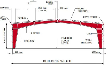
Cold form steel sections are widely used in the construction of warehouses, factories, workshops, offices, gas stations, vehicle parking sheds, show rooms, schools, aircraft hangers, roofs and canopies of stadiums, bridges and railway platform shelters. They are commonly called as pre-engineered buildings (PEB). Figure 1 gives a typical cross section of a PEB building. The major advantages PEBs are reduced construction time, lower cost of construction, flexibility of expansion, suitability for large clear spans, architectural versatility, better incorporation of energy efficiency, better quality control and low maintenance. The rapid growth in the sectors such as automotive, power, logistics, pharma etc have led to robust growth of PEB building segment. The popularity of PEB buildings have promoted the engineers and designers to explore further avenues of application for cold form section to make the construction process very lean and short. The lack of skilled man-power and widely accepted established options in concrete and steel are the major limitations facing PEB building sector from entering other conventional construction domains [1].
PEB buildings as well as to ensure better project completion the prefabrication of mezzanine floor becomes necessary. Such an approach could also be adopted in the other construction practices where labour and time is very critical and helps in the evolution of solutions towards sustainable built environment.
FIGURE 1 A SKETCH OF PRE-ENGINEERED STEEL BUILDING CROSS SECTION [1].
Cold Form Slab Section
Cold form sections are thin sections that are formed in the cold state (i.e. without application of heat) from steel sheets of uniform thickness. These sections are made to various structural section like C, Z , tube and various other shapes. Composite structures combine two or more materials in a unit structure to provide tangible benefits and a versatile solution to suit different applications. A composite system helps to develop sections that are less in weight, without sacrificing the required capacity. The composite sections for precast applications are rapidly on an increase with the development of better construction techniques [2-9]. There are five different capacity criteria to be considered for the full precast flooring units; (1) bearing capacity, (2) shear capacity, (3) flexure capacity, (4) deflection limits, (5) handling restriction [3,5].
An attempt was made for the development of cold form section (CFS) based composite panel which would also help in the reduction of dead load and help in using lighter sections. The composite panel proposed consist of bottom layer of single skin steel sheet and top layer of 10 mm cement boards both connected using cold form C-channel assembly (Fig 2). The total thickness of the panel would be 110 mm and the C-channel assembly is expected to contribute to the required flexural capacity for the prefab panel. The gaps in the C-channel between top and bottom layers are filled using foam insulation. This could also ensure adequate fire and sound insulation. This light weight prefab slab panel was supported on cold form steel joists. Use of cold form joist helps in easy laying of joists without any crane. Further these prefab slab can be connected to cold form joists easily with self drilling screws [7].
The research work undertaken here was aimed to investigate the potential application of cold form sections for designing prefabricated slabs and walls. The preliminary experimental investigation was carried out to evaluate the capability of prefabricated slabs. It was anticipated that the experiments undertaken would help to assess the load carrying capacity of the designed panel. In addition to the strength evaluation, the deflection analysis of the panel was also undertaken using finite element analysis of the panel.
2. MATERIALS AND METHODS
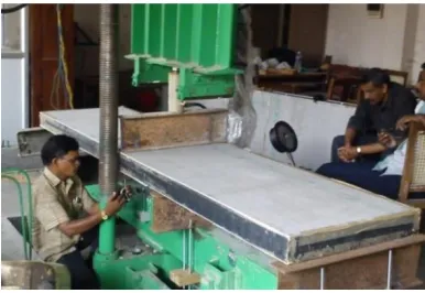
The aim of this study was to experimentally monitor the flexural behavior of prefabricated cold form section (CFS) and undertake numerical simulation of the same. CSF Panel was tested for four different sizes (Table 1). The sizes were designed based on the size of actual panels used for erection at site. Prefabricated composite panel is tested as a three span continuous slab supported at four points. The composite panel is connected to flexural testing machine platform with the help of bolts. The load is applied along the center line of the clear span of the slab in the transverse direction. Dial gauges are located at 3 locations in the span to measure deflection various points and maximum deflection for each load increment is recorded. For the light weight prefab panel serviceability criteria would be dominant than the flexural failure condition as the panel is supported on joists at 1m intervals [4]. Deflection limit of span/240 as per AISC 05 (Allowable Stress Design) is considered and load corresponding at which deflection of span/240 occurs is noted which will be considered as the maximum load carrying capacity of the panel [10]. Further loading is continued to observe the ultimate load. Table 2 shows service load and ultimate load capacity of the panel. An FEM model using 4-noded late element is generated for the composite slab and Deflection is compared with test result for the allowable service load. The experiment was carried out using testing facility at CUSAT structural engineering laboratory.
FIGURE 3 THE EXINGPERIMENTAL ASSESMBLY FOR FLEXURAL TEST
TABLE 1 - DETAILS OF SAMPLE SPECIMENS
Specimen No
Size of the panel
(L×B×H, in mm)
Span of testing
(in mm)
Number of supports
01 3000x700x110 1000 4
3. RESULTS AND DISCUSSION
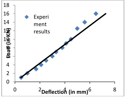
The typical result obtained from the deflection test on the four panel specimen is given in figures 4.
The load – deflection curve of all the four specimen have shown identical behavior The figure3 gives the
plot of mid-span deflection and the load. The load corresponding to the allowable mid-span deflection, 4.1 mm for the member is 7KN. The experiment is continued to the failure of the panel and ultimate load is recorded.
FIGURE 4 – LOAD DEFLECTION GRAPH
TABLE 2 - LOAD ESTIMATION
Speci men No.
Limiting Deflection (span/240) (mm)
Load against limiting deflection(Al lowable load)(KN)
Ultimate Load(KN)
01 4.1 11 32
02 4.1 9 28
03 4.1 7 25
04 3.3 37 100
0 2 4 6 8 10 12 14 16 18
0 2 4 6 8
Load
(
in
KN)
Deflection (in mm)
Experi ment results
03 3000x595x85 1000 4
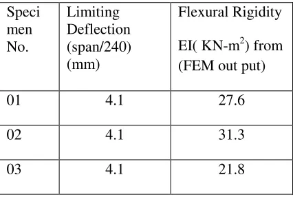
TABLE 3 - ESIMATION OF FLEXURAL RIGIDITY
Speci men No.
Limiting Deflection (span/240) (mm)
Flexural Rigidity
EI( KN-m2) from
(FEM out put)
01 4.1 27.6
02 4.1 31.3
03 4.1 21.8
The test results show satisfactory result for CFS Slab system that could be used for commercial /industrial/residential pre-engineered building. The density of the CFS Slab system used is less than 4
KN/m3 which is only one-sixth weight of a RCC floor slab. For all the test result service loads are found
to be more than 6KN/m2, which is within the permissible live load limit for residential/commercial buildings. For a typical residential building a factor safety of 2 could be ensured in using these panels. Load-deflection curve shows a bi-linear behavior up to this limit. As CFS slab is reinforced with Cold form structure, deflection criteria dominate. By reducing the span from 1000m lesser spacing, the load carrying capacity can be well controlled. The FEM simulations of the panel have given the flexural rigidities of the panels (Table 3). The CFS slab system with its versatile properties is an efficient system available to achieve a light, thin, and stiff structure. System connection behavior was observed in the study and it is concluded that system connection is as good as steel deck slab connection.
4. CONCLUSION
The pre-engineered buildings hold a huge promise for the development of sustainable building practices. The research presented here was related to the application of the cold form steel sections for the development of pre-fabricated floor panel. The flexural tests undertaken on the panels have confirmed the feasibility of using such configurations for various types of floor panels to support live loads. Further, research is needed to understand the behavior of both in-plane and out-of plane loads.
REFERENCES
[1] Zamil Steel, (2005), Pre-engineered steel versus conventional steel building, Information report.
[2] Bonacci, J. F., and Maalej, M. (2000). “Externally Bonded Fiber-Reinforced Polymer for Rehabilitation of
Corrosion Damaged Concrete Beams”. ACI Structural Journal. 97(5):703-711.
[3] Yardim, Y. , (2013). “Performance of Precast Thin Panel as Permanent Formwork for Precast Composite
Slabs”. 2nd International Balkans Conference on Challenges of Civil Engineering, BCCCE, 23-25 May 2013,
Epoka University, Tirana, Albania..
[4] Lukaszewska, E. and Fragiacomo, A., 2003.”Static Performance of Prefabricated Timber-Concrete Composite
Systems”,Thesis-Luleå University of Technology,Sweden
[5] Robert K Dowell ,Joseph W Smith., 2006. “Structural Test of Precast Prestressed Concrete Deck Panels for
California Freeway Bridges, PCI Journal March-April 2006
[6] Mansur , M. A., and Ong, K. C. G. “Composite Behaviour of ferrocement –Deck Reinforced Concrete Slabs”. J. Ferrocement 1986; 16(1): 13-22.
[7] Scott, N. L.,“Performance of Precast Prestressed Hollow Core slab with composite concrete Topping,
Incollection”. PCI Journal November-December 1971
[8] Bernard, E.S., “Behaviour of Round Steel Fibre Reinforced Concrete Panels under Point Loads,” Materials
[9] Soranakom, C., Mobasher, B. and Destrée, X.,“Numerical Simulation of FRC Round Panel Tests and Full
-Scale Elevated Slabs”,National Science Foundation program 0324669-03,
[10]AISC “American Institute of Steel Construction” Manual of Steel Construction - Allowable Stress Design, 2005
Edition.1 East Wacker Drive, Suite 3100, Chicago, Illinois 60601-2001.
[11]Dowell, R.K., August 2005, “Structural Tests of Precast Deck panels for the 22 Freeway” Structural