ISSN(Online): 2320-9801 ISSN (Print) : 2320-9798
I
nternational
J
ournal of
I
nnovative
R
esearch in
C
omputer
and
C
ommunication
E
ngineering
(An ISO 3297: 2007 Certified Organization)
Vol. 4, Issue 2, February 2016
Comparative Analysis of Three Stage and
Three Stage Quadruple Pass EDFA
Configurations
Gayathri Devi A S 1, Pratheesh P 2
PG Student [Optoelectronics], Dept. of ECE, TKM Institute of Technology, Kollam, Kerala, India1 Assistant Professor, Dept. of ECE, TKM Institute of Technology, Kollam, Kerala, India 2
ABSTRACT: Optical fiber communication is one of the most reliable and secure telecommunication technology. When transmitted over long distances, the optical signal is highly distorted. To prevent signal degradation over long distance we need an optical amplifier which provides better Q factor and minimum bit error rate. At the choice of signal amplification method the preference is given to the class of erbium doped fiber amplifier (EDFA). It has the major advantage of being optical amplifier, with no conversion of the optical signal into electrical signal and more suitable at 1550nm wavelength. Stage enhancement of EDFA improves the Q factor and decreases the BER. Thus the overall performance of the transmission schemes such as WDM increases. Multi pass and multi stage configuration of EDFA improves the performance parameters of the amplifying system.
KEYWORDS: Erbium Doped Fiber Amplifier, Bit Error Rate, Quality factor,Optical Fiber Communication, Wavelength Division Multiplexing.
I. INTRODUCTION
Optical fiber communication is one of the most reliable, fastest and secure telecommunication technologies. It has grown in importance exponentially in the present modern era. It is reliable in handling and transmitting data through hundreds of kilometers with an acceptable bit error rate. Optical signal or light is transmitted through optical fibers.
In fiber optic communication, there is a problem of signal degradation during the transmission with increased distance. In order to remove loss limitations, optical amplifiers are used. Optical amplifiers directly amplify the transmitter optical signal without converting it into electric forms. At the choice of signal amplification method the preference is given to the class of erbium doped fiber amplifier (EDFA). EDFAs are optical amplifiers that use a doped optical fibre as a gain medium to amplify an optical signal stage enhancement of EDFA improves the Q factor and decreases the BER. Thus the overall performance of the transmission schemes such as WDM increases.
In an EDFA, population inversion is achieved by optical pumping.to get population inversion it can be efficiently pumped with a laser at a wavelength of 980 nm or 1,480 nm, and exhibits gain in the 1,550 nm region. Amplification is achieved by stimulated emission of photons. The pump laser excites ions into a higher energy from where they can decay via stimulated emission of a photon at the signal wavelength back to a lower energy level. So the signal is amplified along its direction of travel only [1].
ISSN(Online): 2320-9801 ISSN (Print) : 2320-9798
I
nternational
J
ournal of
I
nnovative
R
esearch in
C
omputer
and
C
ommunication
E
ngineering
(An ISO 3297: 2007 Certified Organization)
Vol. 4, Issue 2, February 2016
II. RELATEDWORK
An erbium-doped fiber amplifier configured in a double-pass amplification scheme to improve the performance of the amplifier stage The system provides better Q factor and reduced BER as compared to the single EDFA configuration. The system provides a gain improvement also[3].
Two stage amplification with EDFA improves the gain and overall system performance. The signal get amplified by the first EDFA and the amplified signal is further amplified by the second EDFA. The range of transmission is also increased using this configuration [4].
III.SYSTEM MODELLING
Fiber-optic communication is a method of transmitting information from one place to another by sending pulses of light through an optical fiber. The general block diagram of optical fiber communication is shown in figure 1. Optical amplifiers are used here to reduce the effects of signal degradations by amplifying the incoming optical signal [5].
Fig1: Block diagram of optical fiber communication system
2.1 Three Stage EDFA Configuration
Three stage EDFA configuration is connecting three EDFAs in series to improve the performance of the amplifier stage. The signal get amplified by three EDFAs as shown in figure 2. Signal passes through each EDFA only once. Amplified signal from the previous stage get further amplified here to increases the Q factor and overall performance. Each EDFA is optically pumped by individual pump source. It is just similar to two stage EDFA configuration [2].
Fig 2: Block diagram of three stage EDFA configuration
2.2 Three Stage Quadruple Pass EDFA Configuration
ISSN(Online): 2320-9801 ISSN (Print) : 2320-9798
I
nternational
J
ournal of
I
nnovative
R
esearch in
C
omputer
and
C
ommunication
E
ngineering
(An ISO 3297: 2007 Certified Organization)
Vol. 4, Issue 2, February 2016
Fig 3: Block diagram of three stage quadruple pass EDFA configuration
IV.SIMULATION MODELLING
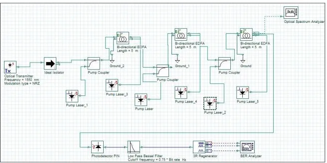
A three stage EDFA configuration consists of an optical transmitter stage which provides the input optical signal. It is passed through an ideal isolator before feeding to the coupler to avoid back reflections. Bi-directional pumping is used here. Three EDFAs are cascaded together to improve the performance of the amplifier stage. Here each EDFA is individually pumped as shown in figure 4. The signal get amplified by the EDFA and output signal is detected by using a pin photo detector. A low pass filter and 3R regenerator is used at the detector part to get the proper signal.The simulation diagram specifies the wavelength of input signal of 1550 nm for the proper working of EDFA. Pumping wavelengths are at 980 nm and 1480 nm. Pump power set to a value of 100 mW.
Fig 4: Simulation layout to analyse three stage EDFA configuration
3.1 Three Stage Quadruple Pass EDFA Configuration
ISSN(Online): 2320-9801 ISSN (Print) : 2320-9798
I
nternational
J
ournal of
I
nnovative
R
esearch in
C
omputer
and
C
ommunication
E
ngineering
(An ISO 3297: 2007 Certified Organization)
Vol. 4, Issue 2, February 2016
Fig 5: Simulation layout to analyse three stage quadruple pass EDFA configuration
V. RESULTS AND DISCUSSIONS
4.1 Three Stage EDFA Configuration
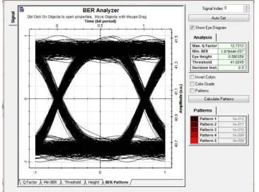
The eye diagram of output optical signal at the detecting section is shown in Figure 6. From the eye diagram the average eye opening and quality factor, minimum BER etc can be obtained. The output signal has a Q factor of 12.73. The minimum BER obtained at the output is 1.97 e-37.
Fig 6: Eye diagram of three stage EDFA configuration
4.2 Three Stage Quadruple Pass EDFA Configuration
ISSN(Online): 2320-9801 ISSN (Print) : 2320-9798
I
nternational
J
ournal of
I
nnovative
R
esearch in
C
omputer
and
C
ommunication
E
ngineering
(An ISO 3297: 2007 Certified Organization)
Vol. 4, Issue 2, February 2016
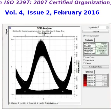
Fig 7: Eye diagram of three stage quadruple pass EDFA configuration
VI.CONCLUSION AND FUTURE WORK
In an optical fiber communication system optical signals are transmitted through the optical fiber. When transmitted over long distances, the optical signal is highly distorted. To prevent signal degradation over long distance communication optical amplifiers are used. EDFA is used as an optical amplifier in communication for better performance. To improve the performance of the amplifier stage muti pass and multi stage EDFA configurations are used. It increases the Q factor and reduces the BER. THree stage EDFA configuration has a Q factor of 12.73 and minimum BER of 1.97e-37. IN the case of three stage quadruple pass EDFA, THe Q factor is 13.87 and BER is 4.21e-44. By comparing the two configurations, three stage quadruple pass configuration has better Q factor and least BER. Thus it has a better performance.
REFERENCES
[1]C. Randy Giles, ‘Modeling erbium-doped fiber amplifiers’, Journal of lightwave technology. vol. 9. no. 2. february 1991.
[2]Fowzia Akhter, M I Ibrahimy, A.W Naji, ‘Design and characterisation of a new three stage quadruple pass EDFA’, Journal of applied science 12(19) 2076, 2012.
[3]Belloui Bouzid, Borhanuddin Mohd. Ali, ‘A high-gain EDFA design using double-pass amplification with a double-pass filter’, IEEE photonics technology letters,vol. 15, no. 9, September 2003.
[4]H. Masuda , A. Takada, ‘High gain two-stage amplification with erbium-doped fibre amplifier’, Electronics letters, vol. 26 no. 10, 10th may 1990.
[5]PC Becker, ‘Erbium Doped Fiber Amplifiers - Fundamentals and Technology’, Optics and photonics, vol. 26 no. 10 10th may 1990.
BIOGRAPHY
Gayathri Devi A Sreceived her B.Tech degree in Electronics and Communication Engineering from Kerala University in 2013. She is currently pursuing second year M.Tech in Optoelectronics and Communication Systemsat TKM Institute of Technology.