ISSN(Online): 2319-8753 ISSN (Print) : 2347-6710
I
nternational
J
ournal of
I
nnovative
R
esearch in
S
cience,
E
ngineering and
T
echnology
(A High Impact Factor, Monthly, Peer Reviewed Journal)
Visit: www.ijirset.com
Vol. 8, Issue 3, March 2019
Operating Cost Reduction by Replacing
Heater in Booster Unit
Mr.J.Jaison1, Mr.J.Jose Priston2, Mr.P.John Rabindranath3, Mr.A.kiruba Samraj4, Mr.F.Elsin Raja5
Assistant Professor, Department of Mechanical Engineering, Francis Xavier Engineering College, Vannarpet,
Tirunelveli, Tamil Nadu, India1
Students, Department of Mechanical Engineering, Francis Xavier Engineering College, Vannarpet, Tirunelveli,
Tamil Nadu, India2,3,4&5
ABSTRACT:In DCW, It contain a captive power plant (Diesel power plant), in that furnace oil is used instead of
diesel fuel for that it contain a booster unit, which consists of deaerator, electrical heater, temperature sensor, and viscometer and control unit. Generally in the booster unit, electrical heaters are used for maintaining the temperature of the fuel (HFO). It consumes more electrical power and the operating cost is high and also it affects the company’s profit. To overcome the drawback, we substitute steam heater instead of electrical heater. So that electricity cost was totally reduced and also utilised the steam from the co-generative power plant.
I. INTRODUCTION
ISSN(Online): 2319-8753 ISSN (Print) : 2347-6710
I
nternational
J
ournal of
I
nnovative
R
esearch in
S
cience,
E
ngineering and
T
echnology
(A High Impact Factor, Monthly, Peer Reviewed Journal)
Visit: www.ijirset.com
Vol. 8, Issue 3, March 2019
A Booster unit which consists of a deaerator, electrical heater, temperature sensor and a control unit. Initially the furnace oil enters the deaerator where the air is removed and it is pumped to the electrical heater and it is heated to a certain temperature controlled by the temperature sensor and the control unit. Our aim is to implement a steam heater in the place of electrical heater by using a bypass valve.
The booster unit is used for pressurizing, cleaning, conditioning and feeding the fuel from the service tanks the engines. The booster part of the oil treatment unit is must is designed to full fill diesel engine suppliers requirements concerning the fuel circulations capacity, supply pressure, viscosity/temperature and filtration fineness.
Captive power plant in DCW consists of two wartsila diesel engines of model 18v32. Where,18-cylinders, v-type,
32cm bore diameter, Each engine produces a power of 6MW. In that we used this for furnace oil instead of diesel fuel.
II. PROPOSED MODEL
EXISTING MODEL:
In the existing model, elctric heater is placed in the booster unit and flow property of furnace oil was control by viscometer. Here we have the block diagrame of the entire unit.
ISSN(Online): 2319-8753 ISSN (Print) : 2347-6710
I
nternational
J
ournal of
I
nnovative
R
esearch in
S
cience,
E
ngineering and
T
echnology
(A High Impact Factor, Monthly, Peer Reviewed Journal)
Visit: www.ijirset.com
Vol. 8, Issue 3, March 2019
FINAL MODEL:
This our final setup of our project , to design a steam heater for the system in the booster unit. we substitute steam heater instead of electrical heater. So that electricity cost was totally reduced and also utilised the steam from the co-generative power plant.
Fig 2.2 Final model
Using electrical heater in the booster unit, the electricity cost and other wages becomes very high, so we are going on for a steam heater to reduce the cost.
In open gravity steam heating systems water is heated to its boiling point 100F (2120C) and steam rises by convection through pipes to heat exchangers located throughout the building, displacing the air in the pipes and radiators.
ISSN(Online): 2319-8753 ISSN (Print) : 2347-6710
I
nternational
J
ournal of
I
nnovative
R
esearch in
S
cience,
E
ngineering and
T
echnology
(A High Impact Factor, Monthly, Peer Reviewed Journal)
Visit: www.ijirset.com
Vol. 8, Issue 3, March 2019
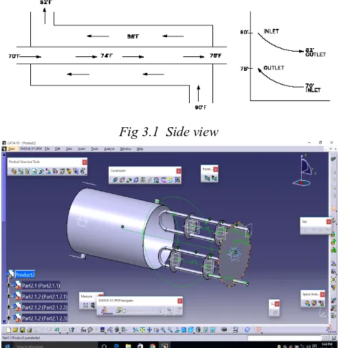
III. MODEL OF STEAM HEATER
Steam is one of the most common and effective heat transfer mediums used in industry, but it is not the only medium available. Other fluids such as hot water and oil are also used for indirect heating in heat exchangers. The following series of articles will focus on the advantages of using steam compared to hot water or oil for heating.
Due to a large number of heat exchanger configurations a classification system as devised based upon the basic operation, construction, heat transfer and flow arrangement
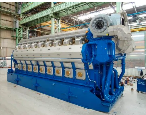
COUNTER FLOW EXCHANGER:
In a counter flow exchanger or concurrent exchanger two fluids flows parallel to each other but in opposite direction within a core. Temperature parallel of the two fluids in such as exchanger may be idealized as one dimensional the counter flow arrangement is thermodynamically superior.
It is a most efficient flow arrangement producing the highest temperature change in each fluid compared to any other two fluid flow arrangements for a given overall thermal conductance fluid flow rate and fluid inlet temperature
Heat exchanger is device used to transfer heat between two or more fluid system at different temperatures. Heat exchanger find wide spread use in power generation, chemical processing, electronic cooling, air conditioning, refrigeration, and automotive application. An important design aspect of heat exchanger technology is the selection of appropriate materials to conduct and transfer heat fast and efficiently.
Copper has many desirable properties for many thermally efficient and durable heat exchangers. First and foremost copper is the excellent conductor of heat. This mean that copper high thermal conductivity allow heat to pass quickly.
Fig 3.1 Side view
ISSN(Online): 2319-8753 ISSN (Print) : 2347-6710
I
nternational
J
ournal of
I
nnovative
R
esearch in
S
cience,
E
ngineering and
T
echnology
(A High Impact Factor, Monthly, Peer Reviewed Journal)
Visit: www.ijirset.com
Vol. 8, Issue 3, March 2019
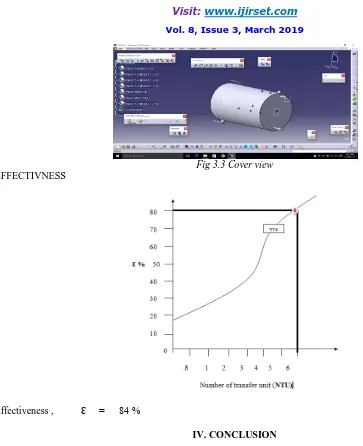
Fig 3.3 Cover view EFFECTIVNESS
Effectiveness , Ɛ = 84 %
IV. CONCLUSION
ISSN(Online): 2319-8753 ISSN (Print) : 2347-6710
I
nternational
J
ournal of
I
nnovative
R
esearch in
S
cience,
E
ngineering and
T
echnology
(A High Impact Factor, Monthly, Peer Reviewed Journal)
Visit: www.ijirset.com
Vol. 8, Issue 3, March 2019
REFERENCES
[1] Jianliua , “The classification of the heat exchangers and theory research”(Nov 2017)
[2] Stephen raj, sathiskumar “Design and analysis of heat exchanger for maximum heat transfer rate”
[3] Bhushan. S, Waghchaure, V.P , Ate “Review on experimental analysis of heat transfer in shell and twisted tube heat exchanger”(AUG 2016) [4]Ravi kumar ,Banjare , Prakashkumarsen ,GopalSahum “A paper on the analysis of effect of material used in heat exchanger and its performances”(OCT 2015)
[5] Arturo Reyes-leon , CelerinoResendiz-Rosas “The design of heat exchangers”
[6] A.Mohan , P. Sankar, S. Ramesh , M.Sathish “CFD Analaysis of double pipe heat exchanger with and without dimples” [7] R.Ramakanth ,k.Karika , P.Varasha , T. Likhitha “Review on shell and tube heat exchangers using helical baffles and non fluids” [8] Prof. S. Y. Sawant, Mr.Sagar E. More“Experimental analysis of advanced materials for Anticorrosive Heat Exchanger” [9] Prabhat Gupta, M.D. Atrey, “Performance evaluation of counter flow heat exchangers considering the effect of heat in leak and longitudinal conduction for low-temperature applications”.
[10] AURUBIS Heat Exchanger Material.