Improvement of Liquid Film Width Prediction Model with
Two-dimensional Film Flow Experiment
Jin-Hwa Yang1, Hyung-Kyu Cho 2, Dong Jin Euh 3, and Goon-Cherl Park 4
1 Ph.D Candidate, Dept. of Nuclear Engineering, Seoul National University, Seoul, Republic of Korea ([email protected])
2 Professor, Dept. of Nuclear Engineering, Seoul National University, Seoul, Republic of Korea 3 Senior Engineer, Korea Atomic Energy Research Institute, Daejeon, Republic of Korea 4 President, KEPCO International Nuclear Graduate School, Ulsan, Republic of Korea
ABSTRACT
Emergency core coolant (ECC) injection by the direct vessel injection (DVI) system is one of the new design features of advanced power reactor 1400 (APR1400). During the reflood phase of the cold-leg break LBLOCA (Large Break Loss-Of-Coolant-Accident), ECC is injected through DVI nozzles to downcomer barrel. Since the DVI line is connected to the upper downcomer region of the reactor vessel (2.1 m above the cold-leg), the injected water falls down to the lower plenum as a liquid film. Previously studies acknowledge the liquid film width on the downcomer wall is as one of the important parameters in the DVI system. Because of that it has concerned with the interfacial area of the liquid and gas and the distance between the ECC and the broken cold leg. Also, the liquid film width affects the ECC bypass fraction. Even a lot of studies regarding liquid film phenomena have carried out, the experimental data on local liquid film behavior is insufficient. This paper presents the previous liquid film width model. Then, the limitation of the model in predicting liquid film behavior was discussed. After that, the experimental result of the local liquid film velocity obtained from 1/10 scaled down facility was introduced. Finally, the limitation of previous model was modified through validation with local experimental data and improvement result was discussed.
INTRODUCTION
The direct vessel injection (DVI) system, injects the emergency core coolant (ECC) directly into a downcomer, is one of the new design features of advanced pressurized water reactors; APR1400, AP1000 and so on. Especially APR1400’s DVI lines are connected about 2.1m above the cold-leg. Due to this high elevation, the ECC injected through the DVI nozzles falls down as a liquid film on the core barrel and interacts with a circumferential steam flowing out the broken cold leg.
On the previous studies, it was found that the width of the falling liquid film influences the bypass of the ECC remarkably since it is related to the interface area between liquid and gas and the relative position of the ECC and the broken cold-leg[Yun et al (2000~2001)]. Therefore, liquid film width experiments had been performed in various scaled test sections including 1/7, 1/5 and 1/1. The effects of liquid flow rates and nozzle diameters on the liquid film width were investigated in the experiments. Also, it was confirmed by these experiment that the difference of the liquid film width affected the ECC direct bypass fraction.
However, this assumption was not sufficiently validated with the local velocity measurement near the impinging jet.
In this study, local liquid film velocity data has been acquired from a 1/10 scaled down experiment in order to validate the Yoon’s liquid film width model. For the local liquid film velocity measurement, the particle image velocimetry (PIV) method was applied. First step with new approach of the measurement method lets us know that the PIV method is applicable to the local liquid film measurement. The assessment result of the Yoon’s model showed the concentric assumption between inlet nozzle and impingement region was not valid in the low inlet velocity condition. Therefore the gravity effect was considered as falling height term in the modeling. Finally, Additional modeling of considering the falling height yields improved result compared with previous Yoon’s model.
LIQUID FILM MODEL
In this chapter, the analytical model that can predict the liquid film width on the core barrel wall proposed by Yoon et al. (2001) is reviewed. Yoon’s model adopted Coleman and Richard’s (1971) suggestion, which said the boundary between the impingement region and the wall jet region for the impingement phenomena, was illustrated in figure 1. Their results yielded the pressure distribution on the flat plate around the stagnation point.
2 rnozzle
Free Jet Region
Impingement Region
Wall Jet Region
Stagnation
r
nozzler
boundaryV
0V
boundaryFigure 1. Impingement phenomena and impingement region
They showed that the radius of the impingement region is about 1.8 times that of the nozzle.
nozzle boundary r
r 1.8 (1)
They assumed a concentric circle between nozzle and impingement boundary since the gravity effect can be ignored in the impingement region because the velocity of the impingement region is very high while the cross-sectional area of the flow is small. Thus the square of velocity is proportional to the potential logarithmic function, i.e.
nozzle boundary
boundary r r
V log /log
However, the aforementioned experimental result about liquid film width shows a liquid jet which was curved downward by the gravity effect and the stagnation point of the impinging jet was lower than the injection elevation. In the full scale model, the stagnation point did not reach the injection elevation even under the highest ECC injection condition. A concentric circle assumption, therefore, was not appropriate method to predict liquid film width.
Yoon’s model dealt the gravitation and the friction force as the important factors in the wall jet region, and derived a governing equation, viz.
friction
F g dt
dV
(3)It can be discretized with incompressible assumption V=1/z, i.e.
1 2 1 2 11
2
1
n n nw n n
v
u
u
f
t
u
u
(4)
1 2 1 2 11
2
1
n n nw n n
v
u
v
f
gV
t
v
v
(5)Initial conditions, u(0) and v(0), were taken from Eq. (2). Also, the wall friction factor should be defined. However, these were not exact values because the assumption of impingement region has limitation to be generalized. Thus, it is necessary to validate Yoon’s model with local liquid film data and the local liquid film velocity measurement was attempted in the present study.
LOCAL LIQUID FILM EXPERIMENT
Description of Test Facility
In order to provide the experimental data for the development and validation of a liquid film width model, local velocity measurement for the falling liquid film was performed. Figure 2 shows the experimental facility for the local velocity measurement. The test facility was devised for the two-dimensional film flow experiment. Therefore it includes the air supply system to provide transverse air flow and the water supply system to simulate the falling liquid film. The interfacial momentum exchange between them will be investigated in the test facility in our future study. Prior to the test, the falling liquid film behavior was measured without air flow in the present study.
Water from storage tank was injected into nozzle by pump. The injected water impinges on the 1.4 m 0.62 m parallel slab geometry test section wall and made a liquid film flowing down on the flat plate wall. And the water returned to the storage tank via the drain line at the bottom of the test section. The spreading width of the liquid film was measured by an image analysis. A transparent grid ruler was attached on the wall for this measurement. The symmetry assumption of liquid film width according to center of the nozzle was applied. Also, the maximum value of liquid film width was selected because the pulsations of liquid film boundary were ignored.
Experimental Method
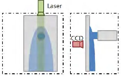
ensure that the liquid film is covered by the LASER sheet in depth and the averaged liquid velocity can be obtained in the direction. Using a traverse system, the LASER sheet was aligned to pass through the liquid film as shown in figure 10.
A high-speed camera (Redlake, MotionXtra HH-100K) was used to capture the images with the reflected laser from fluorescent particles. 500 pairs of images were taken for the present experiment, when the time duration between two pairs and that between two images in a pair were 1/100 and 1/500 seconds, respectively. The field of view was 130 mm 100 mm and a resolution of 1280 960 was applied. In order to cover whole liquid film, the images were recorded at 8 different positions. The recorded images were analyzed by a PIV software. In the process, the images changed into gray-tuned mode, and modified images got through cross correlation which was fixed as 128 64 pixels unit. From the cross-correlation results along with the time duration between two consecutive images and the size of a pixel, the velocity field of the liquid film can be obtained.
Figure 2. Schematic view of liquid film experimental facility
Figure 3. Vertical lighting method with laser and CCD camera
Experimental Result
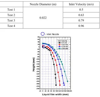
As shown in the table 1, the liquid injection velocity varied from 0.5m/s to 0.96m/s acquired by a turbine flowmeter. These liquid velocity boundary conditions were derived from the modified linear scaling. The 0.63m/s was a reference velocity which was scaled down from real ECC injection condition. And a liquid temperature was 14℃ measured by k-type thermo-couple.
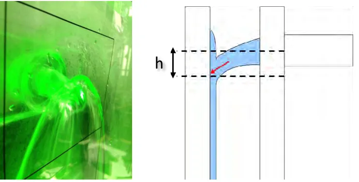
impingement center was (753, 224). This means the concentric circle assumption of the Yoon’s liquid film model is not proper to predict liquid film width. Similar to the visual observation results, the stagnation point was located lower than the center of the inlet nozzle due to the gravity effect.
Table 1: Liquid Film Test Matrix
Nozzle Diameter (m) Inlet Velocity (m/s) Test 1
0.022
0.5
Test 2 0.63
Test 3 0.79
Test 4 0.96
Figure 4. Experiment result of liquid film width measurement
(a) Original photography (b) Local film velocity surround inlet nozzle
Figure 5. Local liquid film velocity surround inlet nozzle by PIV method Impinging jet
region
Subsequently, impinging direction was not perpendicular to the wall and it was shifted down slightly (figure 6). This result implies that Yoon’s model cannot be applied directly for the liquid film under this velocity condition. The velocity field near the impinging jet region will be analyzed more precisely in order to derive a proper boundary condition for the liquid film width model. In particular, the location of the boundary between the wall jet and impinging jet regions and the velocity on the boundary will be derived from this measurement result.
Figure 6. Shifted down impingement direction
ASSESSMENT & MODFIFICATION OF YOON’S MODEL
Assessment of Yoon’s Model
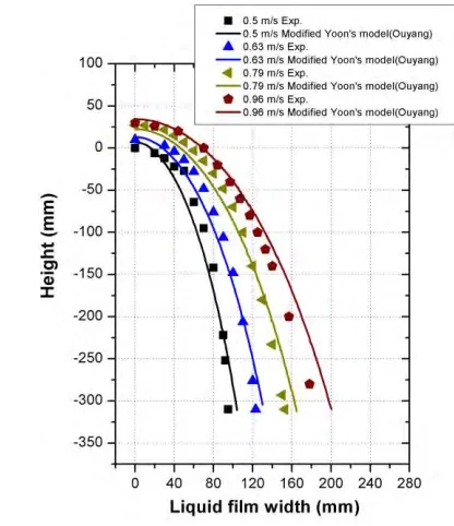
To calculate the liquid film width by Yoon’s model, the wall friction factor should be defined (equations (4) & (5)). The Ouyang’s wall friction model, equation (6), which was developed in liquid-gas annular flow condition with Stanford multi-phase flow database (SMFD) was used in this study. If the volume flow rate of liquid and gas could be assumed as uniform, it can be applied in the film flow condition. Although the difference of flow condition can affect the interfacial friction force, the wall friction force of co-current flow could not be different significantly. It can be confirmed from that the degrees of liquid film width were predicted well as shown in figure 13. However the difference of initial locations between the experimental and calculated results was more dominant discrepancy. This means, the Ouyang’s wall friction model is proper to predict the degrees of liquid film width. But the concentric circle assumption of Yoon’s liquid film model is not proper to predict the liquid film width.
(6)
Aforementioned as shown in figure 5, the concentric circle assumption is not valid in reference velocity which is scaled down from real condition. The lower located impingement region cannot be explained by the first assumption of Yoon’s model. Therefore an additional assumption as to gravity effect is necessary. From inlet velocity and gap between with nozzle to wall, a falling height can be
5161 . 0
Re
6291
.
1
LwL
f
UL
predicted as shown in equation (7). This additional modeling should be considered to modify the Yoon’s model.
(7)
Improved Result of Modified Yoon’s Model
Figure 13 shows the improved result of the modified Yoon’s model. Previous results let us know that the concentric assumption of Yoon’s model is not valid with the experimental results. Since the acquired inlet velocity conditions from modified linear scaling method were already validated with several scaled test geometry, these 1/10 scaled inlet conditions can be assured to yield valid experiment results [Cho et al(2005)]. Therefore, lower located impingement region caused by gravity effect should be considered. The improved result shows that gravity effect modeling yield more accurate than previous one. Thus, the modified Yoon’s model will be used as liquid film width prediction model in our further study.
(a) Result of Yoon’s model (b) Result of modified Yoon’s model
Figure 7. Improvement result from model modification
CONCLUSIONS
In this study, the local liquid film experiment was conducted with a 1/10 scaled down facility to acquire local liquid film data using the PIV method. It was used for the validation of the Yoon’s liquid film width model. According to the assessment result of Yoon’s model, it was confirmed that the concentric assumption was not valid. Considered gravity effect modeling yields more accurate results than previous one. Thus, Yoon’s model was modified through validation work with benchmark data. After validating the model against the flat plate experiment, the modified Yoon’s model will be one-more
2 2
2 1 2
1
u z g gt
modified for a cylindrical coordinate. Then, it will be applied for the previous experimental results performed with various scales of the downcomer models.
ACKNOWLEDGMENTS
This work was supported by the Nuclear Research & Development Program of the National Research Foundation (NRF) grant funded by Korean government (MEST). (No. 2012M2A8A4004176).
NOMENCLATURE
Symbols
F : force
f : friction factor
g : gravity acceleration
h : falling height
L : characteristic length (parcel width)
r : radius
Re : Reynold number
t : time
U : parcel velocity
u : x-direction velocity
v : y-direction velocity
V : velocity
Greek Symbols
: liquid film depth
ρ : density
μ : dynamic viscosity
Subscript
w : wall
wL : wall-liquid interface
Superscript
n : present time
n+1 : advanced time
REFERENCES
Cho, H.K., Yun, B.J., Song, C.-H., Park, G.C. (2005), “Experimental validation of the modified linear scaling methodology for scaling ECC bypass phenomena in DVI downcomer,” Nuclear Engineering and Design, volume 235, issue 21, pages 2310-2322.
Coleman, D. D. and Richard, S. S. (1971), "A study of Free Jet Impingement. Part 1. Mean Properties of Free and Impinging Jets," J. Fluid Mechanics, volume 45, pages 281-319.
Ouyang, Liang-Biao and Aziz, Khalid (1996), “Development of New Wall Friction Factor and Interracial Friction Factor Correlations for Gas-Liquid Stratified Flow in Walls and Pipelines”, Western Regional Meeting SPE 35679, Anchorage, Alaska, Stanford University.
Yoon, S.H., Park, Y.K., Suh, K.Y., Song, C.H., Chung, M.K., Oh, S.J. (2001), “Direct Vessel Impingement Flow into Reactor Downcomer: Experiment and Analysis,” 16th International Conference on Structural Mechanics in Reactor Technology (SMiRT), Washington D.C., USA.
Yun, B.J., Cho, H.K., Kwon, T.S., Song, C.-H., Park, J.K., Park, G.C. (2000), “Experimental observation on the hydraulic phenomena in the KNGR downcomer during LBLOCA reflood phase,” KNS Spring Meeting, Korea Nuclear Society, Republic of Korea.
Yun, B.J., Cho, H.K., Kwon, T.S., Song, C.-H., Park, J.K., Park, G.C. (2000), “Air/water test on direct ECC bypass during LBLOCA reflood phase of KNGR,” KNS Autumn Meeting, Korea Nuclear Society, Republic of Korea.
Yun, B.J., Cho, H.K., Kwon, T.S., Song, C.-H., Park, J.K., Park, G.C. (2001), “Air–water test on the direct ECC bypass during LBLOCA reflood phase with DVI: UPTF Test 21-D Counterpart Test,” J. KNS, volume 33, isuue3, page 315.
Yun, B.J., Cho, H.K., Kwon, T.S., Song, C.-H., Euh, D.J., Park, J.K., Park, G.C. (2001), “Scaling of the direct ECC bypass during LBLOCA reflood phase with direct vessel injection system,” ICONE-9, Nice, France.