Implementing an Electrical System of Aircraft
Drive Model Using Variable controllers and
Active Power Filter System
Jemima.R
1, Sathyamoorthi.S
2P.G. Student, Department of Electrical Engineering, Pandian Saraswathi Yadav Engineering College
Sivagangai, India1
Assistant Professor, Department of Electrical Engineering, Pandian Saraswathi Yadav Engineering College
Sivagangai, India2
ABSTRACT
:
An aircraft electric power system is developing to improve the performance characteristics of the system. The electrical distribution system has only one primary AC source (360-900Hz at 230V) with all the required DC voltage levels being derived from this source. The AC power through LC filters for purification. And then this power is to be converted into DC using converter. The DC loads are fed by two DC bus system 28V and ±270V. But source, converter, frequency is not mentioned specific ratings in conventional system. Under the proposed system synchronous generator is used and frequency 400Hz and voltage rating are selected. The output of the AC is through Active power filter. Active filter is used to eliminate harmonics, correct supply power factor, and minimize the effect of unbalanced loads. This power provides into 24 pulse (12+12) transformers for switching purpose. A transformer rectifier unit (TRU) with passive 24 pulse power converter is used and this power is to be converted into DC. After the DC converter, we applied to the required load. In this process, the power quality of the system is improved by increasing the frequency.so aircraft size will be reduced and also reduced CO2 emission, and thus it supports environmental protection.KEY WORDS: Aircraft electric system, Active power filter(APF), 12 pulse rectifier system, Mat lab simulation
I. INTRODUCTION
The architecture of a conventional civil aircraft consists of a combination of systems; mechanical, pneumatic, hydraulic and electrical systems. These systems have several drawbacks suchas low efficiency and difficulty in detecting leaks in a pneumatic system, the use of gearboxes in a mechanical system, heavy, inflexible piping and the potential leakage of dangerous and corrosive fluids for hydraulic system [1]. The concept of the 'All Electric Aircraft' and the 'More Electric Aircraft' (MEA) have been introduced to overcome some of the drawbacks found in conventional architectures and bring many more attractive advantages, such as improved fuel consumption, and lower maintenance and operation costs [1]- [3]. The electrical power doesn‘t require a heavy infrastructure and is very flexible. However, it still suffers some drawbacks such as a low power density compared to hydraulic power and may result a higher risk of fire in case of a short circuit.The high-voltage DC power line (HVDC), with a nominal voltage of ±270 V can be supplied by two different power sources according to design choices: either an HVDC generator or an auto transformer rectifier unit (ATRU) powered by AC source 2. This high-voltage AC source (HVAC) is 230 V phase to neutral in variable speed variable frequency (VSVF) systems, with a frequency variation between 360 and 900 Hz.
Existing System
normally work in a low-frequency range <1 kHz with bulky magnetics) are eliminated. Their functions are replaced by isolated DC/DC converter(s) with high-frequency transformers (usually within the range 20–100 kHz) All isolated DC/DC converters in the scheme are fed by the output voltage of the AC/DC buck rectifier, at a rated value of 400 V [5–7]. Each DC/DC converter includes current control, in order to regulate and limit the output current in all operating conditions (including implementing output I2t protection). The existing system of AC/DC distribution system is shown in figure 1
Fig.1.Existing System of AC/DC distribution system Proposed system
Proposed system synchronous generator is used and frequency 400Hz and voltage rating are selected. The output of the AC is through Active power filter. Active filter is used to eliminate harmonics, correct supply power factor, and minimize the effect of unbalanced loads. This power provides into 24 pulse (12+12) transformers for switching purpose. A transformer rectifier unit (TRU) with passive 24 pulse power converter is used and this power is to be converted into DC [8-10]. After the DC converter, we applied to the required load. In this process, the power quality of the system is improved by increasing the frequency.
II. DESCRIPTION OF THE SYSTEM
Synchronous Generator
The Boeing 767 aircraft electric power system consists of two independent channels, according to the number of starters/generators in the aircraft and an auxiliary/emergency power unit that contains an additional auxiliary starter/generator to provide power engines starting as well as for emergency back-up. The generating system comprises starter/generators, power control units, and a generator and system control unit. A permanent magnet synchronous generator is a generator where the excitation field is provided by a permanent magnet instead of a coil. The term synchronous refers here to the fact that the rotor and magnetic field rotates in same speed, because magnetic field is generated through shaft mounted permanent magnet mechanism and current is induced into the stationary armature. Synchronous generators are the majority source of commercial electrical energy.
Transformer Rectifier Unit(TRU)
A 12-pulse TRU using an input three-phase transformer with two secondary‗s connected in Y and delta with unit transformation ratio. Two three phase output voltage systems have the same amplitude and 30º phase shift between them. The required phase shifts are obtained by connecting the secondary‗s in Y and delta configurations. The two main advantages to using multi-pulse transformer/rectifier topologies are a reduction in the ac input line current harmonics and a reduction in the dc output voltage ripple. The input current harmonics are reduced through the use of phase shifting transformers. The expressions
Harm = 6kn ± 1 (1.1)
k = any positive integer (1.3) n = number of six pulse converters (1.4)
provides a simple way to calculate the frequency and magnitude of harmonics that will be present in the ac input line current when multi-pulse topologies are implemented. The frequencies at which the harmonics will appear for an n-pulse converter are computed by multiplying 1.1 by the fundamental frequency of the system. The magnitudes of the harmonics are calculated by multiplying 1.2 by the amplitude of the signal at the fundamental frequency.
Converters
To generate the 28 V DC bus voltage, traditional DC/DC converters with transformer isolation are used. The input stage is represented by a half-bridge configuration followed by an isolated centre-tap transformer; the output is a synchronous rectifier using low-voltage MOSFETs with a very low drain source resistance RDS to minimise the conduction losses. Hard switching is employed in order to be able to control the output current and voltage in all load situations, from open circuit to short circuit. The switches used on the input half bridge are standard Si MOSFETs rated at 600 V, because of the fact that the input voltage is stabilised at 400 V. The three phase fully controlled bridge converter has been probably the most widely used power electronic converter in the medium to high power applications. The thyristors in the converter circuit are commutated with the help of the supply voltage in the rectifying mode of operation and are known as Line commutated converter. The same circuit while operating in the inverter mode requires load side counter emf. A DC capacitor is connected at the output of the power converter to smooth out the DC voltage..
DC Loads
In the proposed VSCF aircraft electric power system model, three different types of DC loads totalling 35.6-kW are connected to the regulated 270-VDC bus through various DCDC converters. All controlled DC loads employ the simplest type of DC-DC converter configurations in which only one switch is needed, and hence significantly minimizing switching losses. These loads are classified as constant power (CP) loads, constant current (CC) loads, and constant voltage (CV) loads. The DC loads are distributed throughout the aircraft and used for various purposes, including heating services, actuation, subsystem controllers and avionics systems.
Constant Voltage
Because of its convenience, versatility, and inherent protection features, many Agilent supplies employ the CV/CC circuit technique. Notice that only low power level circuitry has been added to a constant voltage supply to make it serve as a dual-purpose source. Two comparison amplifiers are included in a CV/CC supply for controlling output voltage and current.. It is obvious that the two comparison amplifiers cannot operate simultaneously. The constant voltage of the system is shown in figure 2
Constant Power
Switching dc-dc converters are often used in portable or battery backed projects because of their broad input voltage range and high efficiency. These converters present a constant-power load to the battery—their input current increases as the battery voltage decreases. By definition of current, charge is removed from the battery faster as the discharge progresses. If it‗s early in the product-development cycle, however, a prototype may not yet be available for testing, so a dummy load of some sort is required. Using a constant-current or constant-resistance load risks overestimating the capacity of the battery, because the current never increases. The constant power of the system is shown in figure 3
Fig. 3.Constant Power Constant Current
The ideal constant current power supply exhibits infinite output impedance (zero output admittance) at all frequencies. The ideal constant current power supply would accommodate a load resistance change by altering its output voltage by just the amount necessary to maintain its output current at a constant value. Constant current power supplies find many applications in semiconductor testing and circuit design, and are also well suited for supplying fixed currents to focus coils or other magnetic circuits, where the current must remain constant despite temperature-induced changes in the load resistance. The constant current of the system is shown in figure 4
Fig. 4.Constant Current
Active Filters
filters. It will not turn a novice into a filter designer, but it can serve as a starting point for those wishing to learn more about filter design.
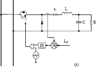
Modelling of controllers
Fuzzy logic, PI controlled shunt active power filter used to compensate for harmonic distortion in three-phase four-wire systems. The presented Shunt Active Power filter is able to operate in balanced, unbalanced and Variable load conditions. Various harmonic mitigation techniques have been proposed to reduce the effect of harmonics. These techniques include phase multiplication, passive filters, active power filters (APFs), and harmonic injection. One of the most popular APFs is the shunt active power filter. It is mainly a current source Connected in parallel with the non-linear loads.Recently, fuzzy logic controller has generated a great deal of Interest in various applications and has been introduced in the power electronics field. The advantages of fuzzy logic controllers over the conventional PI controller are that they do not need an accurate mathematical model; they can work with imprecise inputs, can handle nonlinearity, and may be more robust than the conventional PIcontroller. Classic filters may not have satisfactory performance in fast varying conditions. But auto tuned active power filter gives better results for harmonic minimization, reactive power compensation and power factor improvement. The proposed auto tuned shunt active filter maintains the THD well within IEEE-519 standards.
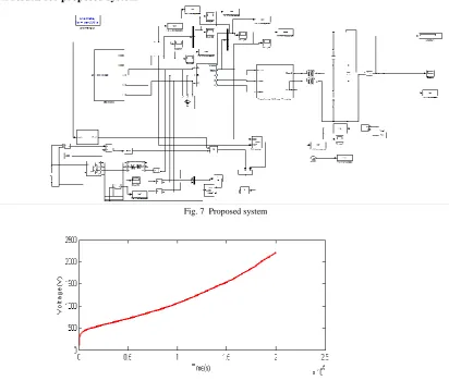
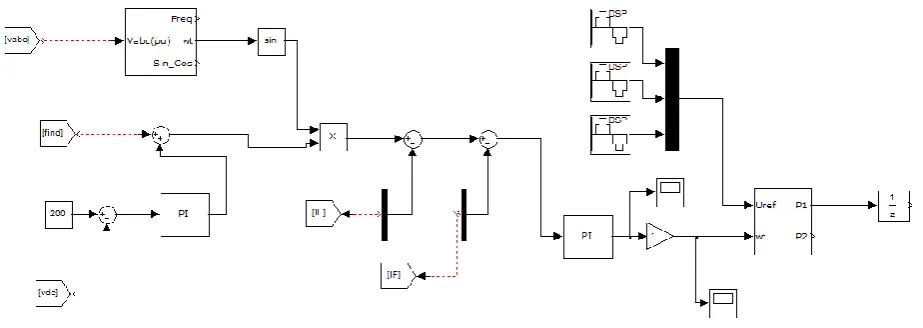
III. SIMULATIONS RESULTS Simulation results for proposed system
Fig. 7 Proposed system
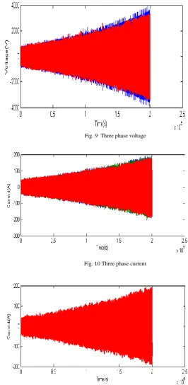
Three phase voltage and current
Fig. 9 Three phase voltage
Fig. 10 Three phase current
Field current
Field Voltage
Figure12 Field Voltage
Figure 13 The test system simulation with balanced nonlinear load
Figure 13 Control strategy for shunt APF with PI Controller
IV. CONCLUSION
A new model of the aircraft electric power system is developed to improve the performance characteristics of the system. Synchronous generator, 24 pulse converter with transformer has been presented. Under the proposed system Synchronous generator is used and frequency (400Hz), voltage rating is mentioned. Active filter is used to eliminate harmonics, correct supply power factor, and minimize the effect of unbalanced loads. In this process, the power quality of the system is improved by increasing the frequency. so aircraft size will be reduced and also reduced CO2 emission, and thus it supports environmental protection. The proposed converter has been verified through computer simulation results. The output voltage can achieve 2200 V with input voltage of 200 V.
REFERENCES
[1]J. A. Rosero, J. A. Ortega, E. Aldabas, and L. Romeral, ―Moving towards a more electric aircraft,‖ IEEE Aerosp. Electron. Syst. Mag., vol.22, no. 3, pp. 3–9, Mar. 2007.
[2] K. W. E. Cheng, ―Comparative study of AC/DC converters for more electric aircraft,‖ in Proc. Inst. Elect. Eng. Power Electronics and VariableSpeed Drives Conf., 1998, pp. 299–304.
[3] A. Eid, M. Abdel-Salam, H. El-Kishky, and T. El Mohandes, ―Simulation and transient analysis of conventional and advanced aircraft electric power systems with harmonic mitigation,‖ Elect. Power Syst. Res., vol. 79, no. 4, pp. 660–668, Apr. 2009.
[4] S. Chandrasekaran, D. K. Lindner, and D. Boroyevich, ―Analysis ofsubsystem integration in aircraft power distribution systems,‖ in Proc.IEEE Int. Symp. Circuits and Systems, 1999, vol. 5, pp. 82–85.
[5]A.Stupar,T.Friedli, J. Minibock,J W .Kolar,Towards a 99% efficient three-phase buck-type PFC rectifier for 400-V DC distribution systems, IEEE Trans. Power Electron., 2012, 27, (4), pp. 1732–1744
[6]A.Pratt,P.Kumar, T V.Aldridge Evaluation of 400 V DC distribution in Telco and data centers to improve energy efficiency. Proc. 29th Int. Telecommun. Energy Conf., Rome, Italy, October 2007,
[7] A. MatsumotoA.FukuiT.Takeda K. Hirose M. Yamasaki Development of 400 Vdc power distribution system and 400 Vdc output rectifier . Proc. 31st Int. Telecommun.Energy Conf., Incheon,Korea, October 2009, pp.
[6] F.Barruel,N.Retiere, J.L Schanen,A.Caisley, Stability approach for vehicles DC power network: application to aircraft on-board system. IEEE 36th Power Electronics Specialists Conf., 2005 (PESC ‘05), 2005, pp. 1163–1169
[9]G.Gong, M.L Heldwein , U.Drofenik , J.Minibock , K.Mino,Comparative evaluation of three-phase high-power-factor AC-DC converter concepts for application in future more electric aircraft, IEEE Trans. Ind. Electron., 2005, 52, (3), pp. 727–737