Cellular Wireless Systems With Joint
Interference Mitigation And Load Balancing
Meepa Mathew
1,
Dhanya S
2PG Scholar, Dept. of ECE, FISAT, Kerala, India
, Assistant Professor, Dept. of ECE, FISAT, Kerala, India
ABSTRACT: The existence of relay stations in MCN raises the issue of efficient allocation of frequency resources to
relay links, the effect of co-channel interference near the cell edges will degrades the system performance and the unbalanced user distribution in cells will result in traffic congestion and thereby guaranteed quality of service can‟t be achieved. An OFDMA based multi-hop cellular network is proposed to overcome this which focuses on downlink of OFDMA in TDD mode. To mitigate the CCI effects due to mobile stations near cell edges and to maintain the spectral efficiency, an efficient interference mitigation scheme is introduced along with an orthogonal resource allocation mechanism. To avoid the traffic congestion due to user overload, load balancing is performed jointly with interference coordination scheme. A system-level simulator is developed in a multi-user environment and the simulation results assure that the new system architecture with the associated algorithm yield higher SINR and data throughput.
KEYWORDS: Multi-hop cellular networks; OFDMA; LTE; Interference mitigation; Load balancing.
I. INTRODUCTION
Multi-hop Cellular Networks (MCN) was proposed by Lin and Hsu for wireless communications called Multi-hop Cellular Network (MCN) as a viable alternative to the conventional Single-hop Cellular Network by combining the features of SCN and ad-hoc networks. MCN preserves the benefit of conventional single-hop cellular networks where the service infrastructure is constructed by fixed bases, and it also incorporates the flexibility of ad-hoc networks where wireless transmission through mobile stations in multiple hops is allowed.. The idea of MCNs is based on multi-hop relaying. The source node signals are relayed through other intermediate nodes to the BS. The intermediate nodes can be fixed, mobile or ad hoc relays. The advantages of MCNs over Single-hop Cellular Networks (SCNs) include more frequency reuse, higher tolerance to BS failures, higher scalability than ad-hoc networks and lesser contention and fewer collisions if we use a contention based MAC protocol. Also it can reduce the required number of bases or improve the throughput performance, while limiting path vulnerability encountered in ad-hoc networks, the capacity can be enhanced, the coverage can be extended, the hot spot and dead spot problems can be alleviated and the radio resource can be better utilized. MCNs can provide service in „dead spots‟ in a cell, which are not reachable by the BS in a single hop.
Although the MCN concept has many benefits, MCNs raise a number of issues, linked to architectural design, the computation of the cell size, maximizing capacity, higher packet delay, resource scheduling, routing, load balancing, co-channel interference effects, power control, assuring quality of service (QoS), and providing security. The main three issues which are not well addressed in MCNs are - co-channel interference in MCN due to the MSs near the cell edge, the difficulty in efficiently allocating the frequency resource and the traffic congestion in the system due to the unbalanced distribution of users in a cell/sector. The interference effect will degrade the network performance and the unbalanced user distribution will make it difficult for the system to provide the guaranteed QoS to users. To overcome these problems an OFDMA based MCN is proposed which jointly provides the interference mitigation based on an orthogonal resource allocation mechanism and load balancing through handover mechanisms. The joint interference coordination and load balancing method will helps the MCN to mitigate the interference effects under balanced distribution of users and thereby throughput and system performance can be improved.
II. RELATED WORK
(BS) and mobile stations (MSs) through multi-hop communication can improve the coverage [1]. IEEE 802.16j standardization activity, provide relay capabilities to IEEE 802.16 systems [2], [3] to provide performance improvements necessary to support future advanced services and applications. The 802.16j task group define RSs with significantly lower complexity and lesser functionalities than a BS, so that an operator could deploy a network at a lower cost instead of using only expensive BSs which will helps to extend the high-data-rate coverage to remote areas in the cellwhile delivering a required level of service to users and to overcome poor channel conditions[4]. The orthogonal frequency-division multiplexing (OFDM) air has the inherent ability to combat frequency-selective fading and it helps to enhance per-link throughput. Orthogonal frequency-division multiple access (OFDMA) based radio resource allocation schemes allocate different portions of radio resources to different users in both the frequency and time domains to effectively exploit the benefit of RSs. Various crucial issues for the successful implementation of OFDMA based multi-hop cellular networks were discussed in [5]. An overview of contemporary and forward looking inter-cell interference coordination techniques for 4G OFDM systems with a specific emphasis on implementations for LTE is given in [6]. Fractional frequency reuse (FFR) is an interference mitigation technique which involves partitioning the usable spectrum into a number of subbands and assigning a given subband to a cell in a coordinated manner that minimizes inter-cell interference. To achieve a high data rate cellular network, it requires a highly efficient utilization of the available spectrum. For that, frequency reuse with factor of 1 is likely to be used in LTE-Advanced and IEEE 802.16m systems, aiming at improving the spectral efficiency [7]. Based on the worldwide interoperability for microwave access (WiMAX) Forum [8], the frequency reuse pattern is denoted as N x S x K, representing clusters of N cells with S sectors and K different frequency bands per cell. Also, in [9] and [10] the performance of OFDMA frequency re-use schemes is analyzed with a particular emphasis on LTE. The simulated results of [10] claim that a frequency re-use scheme of N = 1 provides the best overall throughput for both the UL and DL.
In [11], a relay-based orthogonal frequency planning strategy is proposed to improve cell edge performance and to reduce interference. In [12], fractional frequency reuse (FFR) is extended to MCNs as a compromise solution to reduce CCI while maintaining the sector frequency reuse factor as 1. The main idea of FFR is to adopt frequency reuse 1 x 3 x 1 at the cell center to maximize the network spectral efficiency while harnessing frequency reuse 1x3x3 at the cell edge to alleviate CCI. In [13], the minimum CCI has been achieved by adjusting the transmission power at BSs and RSs under orthogonal frequency resource allocation. Four different existing cell-based sub-channel allocation schemes with different partition factors and reuse factors for downlink transmissions in the two-hop OFDMA relay-enhanced cellular system were taken into consideration in [14]. As important methods in load balancing, the cell breathing and load-ware handover are proposed in [15]. An extension of Round-Robin algorithm and two special algorithms - greedy polling and partial proportional fair (PPF) are proposed in [16] for adaptive resource scheduling for OFDMA based cellular networks in TDD mode. In [18], a simple but efficient radio resource management algorithm was proposed which enables the spatial resource reuse for interference-free users operating in the high signal-to-interference-and-noise ratio (SINR) region, while guaranteeing the signal quality of interference-susceptible users usually located near the coverage boundary.To maximize the weighted sum data rate in multi-cell and multi-carrier wireless data systems and to improve the system performance, an earlier proposed scheme jointly considers load balancing, user scheduling, and interference mitigation [19]. For this, they divide the joint problem into a load balancing and scheduling sub-problem which is a NP-hard problem and an interference mitigation sub-problem and then propose algorithms for each sub-problem. Frequency reuse and load-balancing schemes were jointly optimized in [20] and [21] to mitigate the interference and to balance the network load in a multicell network.
III.PROPOSED ORLB SCHEME
A. System model
A cellular network with a cluster of 19 hexagonal cells as in fig. 1 is considered as the proposed MCN in which each cell is divided into three sectors. Each sector in each cell is provided with a BS at the centre of cell and two RSs at the edges of sector. Mobile Stations are also provided inside the cells and near to the cell edges. The proposed cell structure is illustrated in fig. 2.
B. Interference Coordination
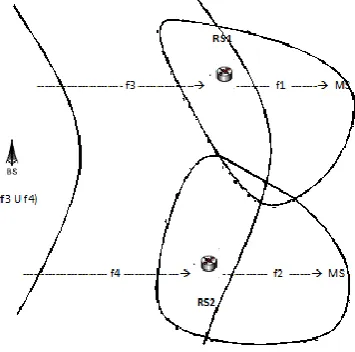
to the sector edge area, while f3 & f4 are allocated to the inner sector area as shown in fig. 3. The relays will convert the frequency bands from the inner area to the cell edge area.
Fig. 1 : MCN with 19 hexagonal cells Fig. 2 : Cell structure and its division
The first relay will convert the f3 band received from the BS to the f1 band that will be assigned to the edge MSs in the coverage area of the first relay. Similarly, the second relay will convert f4 to f2. Since frequency bands f3 & f4 are used for BS-RS communication, they cannot be used for the MSs inside the sector because the relay is also treated as MSs in view point of the BS. Therefore, to maintain the sector frequency reuse factor as 1 and to avoid the intra-cell interference, frequency bands f1 & f2 are used for the BS-inner MS communication with a much reduced signal power. Consequently, the new system architecture has the same frequency reuse factor as the conventional system architecture without relays, but the ICI of the cell-edge MSs is considerably reduced. However, the frequency resource allocated for each MS follows a certain priority, based on the location of the MS and the available resource.
Fig. 3 : Frequency conversion in one sector
The proposed ORAA is implemented in two steps - Firstly, it is implemented at BSs for BS-inner MS (BS-iMS) and BS-relay (BS-RS) communications. With the above frequency converting scheme for relays, any subcarrier used in the cell edge areas can be reused for BS-iMS communications with a much reduced transmission power. To make the distance between the sub-carriers used by the inner MSs and the edge MSs of the same sector as far as possible, the BS searches for available carriers in each sector starting in the opposite direction to the relay search. Available sub-carriers are the sub-sub-carriers that have not been used for B-iMS and BS-RS communications in the same sector. That is, for inner MSs in sector 1, the BS will start searching from the rightmost point of the system bandwidth to the left. Similarly, the BS will start searching both from the leftmost and rightmost points to the center if inner MSs are located in sector 2 and from the leftmost point to the right of the system bandwidth if inner MSs are located in sector 3. The algorithm for the proposed ORAA for BS-iMS and BS-RS communication is as follows :
(lowest)
2) For each sector i where i=1,2,3; as, m= 0 to W-1, go to steps 3 and 4 3) Subcarrier priorities in each sector is assigned as,
p1[m] = W-1-m; p3[m] = m; p2[m] = m/2 ; //at center for even m OR p2[m] = W – 1 – (m-1)/2 //at center for odd m
4) Available subcarriers in sector i with priority m is set as, subi[m] = 0; 5) To assign n subcarriers for kth inner MS, go to steps 6 to 9
6) For every inner MS or relay k in sector i where i=1,2,3; go to steps 7 to 9 7) For l = 1 to n; go to steps 8 to 9
8) For m = 0 to W-1; go to step 9
9) if available subcarriers with priority m equals to zero ie; (sub[ pi[m] ] == 0) then assign this subcarrier for inner MS/relay k as, subi[ pi[m] ] = k
Secondly, it is implemented for Relay-edge MS (RS-eMS) communications. Assuming that the kthedge MS located in the cell-edge of sector 1 starts to activate, the serving relay will start to search for available sub-carriers from the left of the system bandwidth to the right. The first available sub-carriers will be assigned to the kthedge MS. Available sub-carriers are the sub-sub-carriers that have not been used by other edge MSs in the same cell-edge and the adjacent cell edge areas of MS k. Information about used (available) and unused sub-carriers in the same cell edge area or between adjacent cell-edge areas is controlled by the control information exchanged between BSs. The algorithm for the proposed ORAA for RS-edge MS communication is as follows:
1) For each sector i, where i = 1,2,3; as m = 0 to W-1, go to steps 2 to 2) Subcarrier priorities in each sector is assigned as,
p1[m] = m; p3[m] = W – 1 – m; p2[m] = W/2 - m/2; //at center for even m OR p2[m] = W/2 + (m+1)/2 //at center for odd m
3) Available subcarriers in sector i with priority m is set as, subi[m] = 0; 4) To assign n subcarriers for kth edge MS, go to steps 5 to 8
5) For every edge MS k in sector i where i=1,2,3; go to steps 6 to 8 6) For l = 1 to n; go to steps 7 to 8
7) For m = 0 to W-1; go to step 8
8) if available subcarriers with priority m equals to zero ie; (subi[ pi[m] ] == 0) then assign this subcarrier for edge MS k as, subi[ pi[m] ] = k
By using the proposed algorithm to assign sub-carriers, the sub-carriers of all MSs at adjacent cell-edge areas will never be overlapped. This eliminates the ICI significantly. Moreover, all MSs in a cell (both inner MSs and edge MSs) can utilize the total system bandwidth as mentioned before. Consequently, the sector frequency reuse factor is always maintained at 1. The only sub-carrier overlapping possibility occurs when many MSs at the same cell are active simultaneously. Some subcarriers can be used at the same time in different sectors of the same cell. However, this probability is small and the intra-cell interference is not serious.
C. Load balancing
as link qualities between RSs and MSs are reported to BS by RSs. The BS is directly responsible for performing handover mechanisms in each sector.
When an RS is overloaded, it does not have enough frequency resource for the users nearby. Therefore, the proposed LB based handover mechanism for traffic load at RS focus on switching some users from the congested RS to some non-congested BSs in the same sector to keep traffic load in balance and reduce the blocking probability. The handover mechanism can‟t be done from the congested RS to other non-congested RS because the low Tx power at RS imposes limitation on the coverage area of RS and so the users associated with one RS cannot establish connections with the other RS in the same sector. Also no more spectrum can be added to the congested RS because it would violate the IC rules that the users at the cell edge are only allowed to use orthogonal frequency bands with the adjacent-sector RSs.
The following is the detailed procedure for the proposed handover mechanism: Step 1 : Measurement and report
The BS periodically measures and computes the average data rate for any user associated with RSs so that the BS has the knowledge of the RS‟s load status. When a new user arrives at the RS, the BS will determine whether the RS is overloaded and announce the information about its own load status together.
Step 2 : Decision and execution
If the RS is determined to be overloaded, and the BS has available resource to accept more users, some users originally associated with the RS will change their serving station from the RS to the BS. However, the BS cannot always cover the place where a new arrival arises, and the optimal value of the throughput cannot be obtained by the handover of the new arrival either. Therefore, the BS needs to calculate the expected data rate if a user is switched to the BS, and choose user n‟ that can achieve the largest benefit ( ie; data rates of user n‟ have the smallest difference between its connections with the BS and the RS) by switching serving station. If more than one user achieves the same largest benefit, one user is randomly selected. If the user is a valid candidate, the handover is carried out and the user receives data through direct link from the BS. If the RS is still overloaded, the next eligible user will be selected to connect to the BS until the RS is no longer overloaded or the BS is unable to admit any other users. If some users associated with the RS change their connections to the BS, while there are new users to connect to the BS, this may result in collision. Thus, the BS should first choose the new users associated with the BS to approach the optimal throughput because they have higher slot efficiency and less system overhead.
Step 3 : Notification
To prevent possible ping-pong effects, the users switched to the BS are not switched back to the RS even if the traffic load is reduced at the RS. Because the handover mechanism between a BS and an RS is implemented in one sector, it brings less delay and system overheads than LB among cells in the traditional sense. Thus, the handover should be performed on a short time scale.
When a BS is overloaded, it is not helpful to switch the users associated with the BS to an RS in the same sector. Because these kinds of users are close to the BS and far from RSs, handover mechanism results in decrease of data rates of these users. Therefore the BS will try to add more resources to accommodate more users and to compensate for the overload in it. The following is the detailed procedure for the proposed handover mechanism:
Step 1 : Measurement and report
The BS periodically measures and computes the average data rate for any user associated with it. When a new user arrives at the BS, the BS will compare its average data rate with Rmin to determine whether it is overloaded or not. Step 2 : Decision and execution
can calculate the throughput and the change of throughput is affected only by the handover of the users from the outer zone to the inner zone.
Step 3 : Notification
If the handover of some users to the inner zone improve the throughput, then, BS will reduce the transmit power of inner zone users and carry out the handover mechanism and thereby accept the new users; else, the handover mechanism is terminated and the new users will be rejected because admitting new users will deteriorate the network performance.
IV.EXPERIMENTAL RESULTS
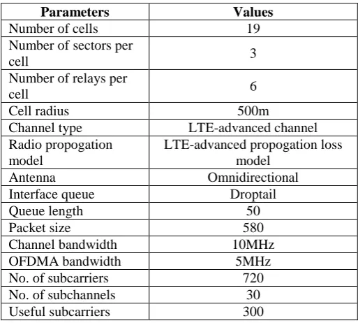
The proposed ORLB scheme is evaluated based on simulation study by using the Network Simulation 2(NS2) tool. A multi-hop cellular network with 19 hexagonal cells is simulated using NS2.The detailed system-level simulation parameters are shown in table I.
Table I : System-level simulation parameters
The end-to-end delay, Packet Delivery Ratio (PDR), throughput and Signal-to-interference plus noise ratio (SINR) are the four performance metrics analysed for the comparison of NFRS, ORAA, ICLB and ORLB schemes of a multi-hop cellular network using NS2 simulator. At first, the users are assumed to arrive under uniform distribution and the total traffic load of cell is set at 150. The mobility model uses random waypoint model in a rectangular filed of 5000m x 5000m. The whole cell area can be partitioned into two non-overlapping concentric areas, i.e., the center area and the edge area. The center area is within 450 meters of BS, and the rest area is the edge area. The total traffic load in a sector is set at 50, and the user distribution is changed by varying traffic loads in the center area and the edge area, respectively.
A. End-to-End Delay (e2e)
End-to-end delay refers to the time taken for a packet to be transmitted across a network from source to destination. In multi-hop cellular networks, it is a critical parameter for quality of service (QOS) guarantees. The difference between the ending time at receiver and starting time at sender of a packet will gives the end-to-end delay of a network. Average end-to-end delay is measured based on the total number of received packets. It can be obtained by computing the mean of end-to-end delay of all successfully delivered messages. Therefore, end–to-end delay partially depends on the packet delivery ratio. As the distance between source and destination increases, the probability of packet drop increases. The average end-to-end delay includes all possible delays in the network i.e. buffering route discovery
Parameters Values
Number of cells 19
Number of sectors per
cell 3
Number of relays per
cell 6
Cell radius 500m
Channel type LTE-advanced channel Radio propogation
model
LTE-advanced propogation loss model
Antenna Omnidirectional
Interface queue Droptail
Queue length 50
Packet size 580
Channel bandwidth 10MHz
OFDMA bandwidth 5MHz
No. of subcarriers 720
No. of subchannels 30
latency, retransmission delays at the MAC, and propagation and transmission delay. Mathematically it can be shown as equation (1).
𝐷 = 1
𝑛 𝑇𝑟𝑖− 𝑇𝑠𝑖 ∗ 1000
𝑛
𝑖=1 Eq. (1)
D Average end-to-end delay; i Packet identifier or Sequence number Tri Reception time; Tsi Send time; n Number of packets successfully delivered
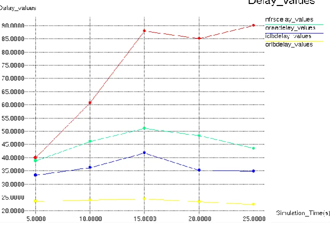
A comparison of the end-to-end delay parameter for the NFRS, ORAA, ICLB and ORLB schemes were done and plotted using xgraph tool as shown in fig. 4. The delay is appeared to be very high for the NFRS scheme while the ORLB scheme outperforms all the other schemes. The joint interference mitigation and load balancing in ORLB scheme helps to decrease the delay of packets in a wide manner and thereby enabling a smooth communication in the network.
Fig. 4 : End-to-end delay values under NFRS, ORAA, ICLB, ORLB schemes
B. Packet Delivery Ratio (PDR)
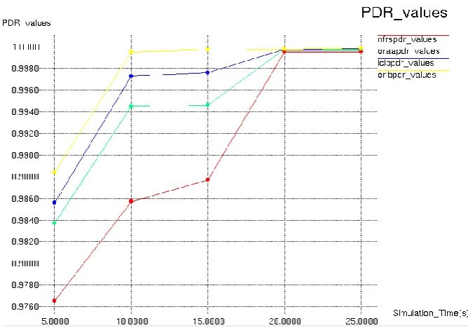
Packet Delivery Ratio (PDR) refers to the ratio of packets that are successfully delivered to a destination compared to the number of packets that have been sent out by the sender. In other words Packet delivery ratio is the ratio of number of packets received at the destination to the number of packets sent from the source. The performance is better when packet delivery ratio is high. Mathematically it can be shown as equation (2).
PDR = ( Total packets received by all destination node )
( Total packets send by all source node ) Eq. (2)
Fig. 5 : PDR values under NFRS, ORAA, ICLB, ORLB schemes
C. Throughput
Throughput refers to the amount of data transferred from one sender to receiver or processed in a specified amount of time in a network.in other words, it is the number of packets/bytes received by source per unit time. Data transfer rates for networks are measured in terms of throughput. Typically, throughputs are measured in kbps, Mbps and Gbps. Average throughput is the average of the total throughput. Mathematically it can be shown as equation (3).
Average throughput = (recvdSize/(stopTimestartTime))*(8/1000) Eq. (3) where, recvdSize Store received packet's size
stopTime Simulation stop time; startTime Simulation start time
Fig. 6 shows the sector throughput of a multi-hop cellular network under various schemes like NFRS, ORAA, ICLB and ORLB. It demonstrates that ORLB scheme provides a slightly better performance than the ICLB scheme and it outperforms the other two schemes because it allows dynamic resource allocation according to the load status.
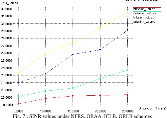
D. Signal-to-Interference-Plus Noise Ratio (SINR)
Signal-to-interference-plus-noise ratio (SINR) refers to the ratio of power of signal of interest to interference noise power which defines the quality of the network. According to the results of comprehensive comparisons in terms of signal to interference, ORLB scheme attains better performance compared to others as in fig. 7.
Fig. 7 : SINR values under NFRS, ORAA, ICLB, ORLB schemes
Table II : Simulation results under four schemes
Schemes
Parameters
NFRS ORAA ICLB ORLB
Average End-to-end delay (ms) 74.1899 42.1616 36.2986 23.3159
Packet Delivery Ratio(PDR) 0.9898 0.9945 0.9960 0.9997
Average throughput(kbps) 1029.16 1059.05 1084.65 1099.72
Average SINR 19.954 21.696 25.312 27.53
Table II shows the simulation results of ICLB and ORLB mechanisms along with that of NFRS and ORAA scheme. The simulation results show that the joint interference mitigation and load balancing using ORLB scheme has the best all round performance.
V. CONCLUSION AND FUTURE WORK
network performance compared to that based on a frequency reuse scheme (ICLB). The proposed method of ORLB helps in network planning and better resource allocation in the future cellular networks.
REFERENCES
[1] S.W. Peters, A.Y. Panah, K.T. Truong, and R.W. Heath Jr., “Relay Architectures for 3GPP LTE-Advanced,” EURASIP J. Wireless Comm. and Networking, article 618787, May 2009.
[2] VaskenGenc, Sean Murphy, Yang Yu and John Murphy, “Ieee 802.16j Relay-Based Wireless Access Networks: An Overview”, Wireless Communications, vol. 15, Issue 5, pp. 56-63, Oct. 2008.
[3] IEEE P802.16m/D6, Draft Amendment to IEEE Standard for Local and Metropolitan Area Networks Part 16: Air Interface for Fixed and Mobile Broadband Wireless Access Systems, IEEE, May 2010.
[4] M. Salem, A. Adinoyi, H. Yanikomeroglu, and D. Falconer, “Opportunities and Challenges in OFDMA-Based Cellular Relay Networks: A Radio Resource Management Perspective,” IEEE Trans. Vehicular Technology, vol. 59, no. 5, pp. 2496-2510, Jan. 2010.
[5] Basak Can, MaciejPortalski, Hugo Simon Denis Lebreton, and Simone Frattasi, “Implementation Issues for OFDM-Based Multihop Cellular Networks”, IEEE Communications magazine, vol. 45, issue 9, pp. 74-81,Sept. 2007.
[6] G. Boudreau, J. Panicker, N. Guo, R. Chang, N. Wang, and S. Vrzic, “Interference Coordination and Cancellation for 4G Networks,” IEEE Comm. Magazine, vol. 47, no. 4, pp. 74-81, Apr. 2009.
[7] Y. Wang, S. Kumar, L. Garcia, K.I. Pedersen, I.Z. Kovcs, S. Frattasi, N. Marchetti, and P.E. Mogensen, “Fixed Frequency Reuse for LTE-Advanced Systems in Local Area Scenarios,” Proc. IEEE 69th Vehicular Technology Conf., pp. 1-5, Apr. 2009.
[8] “WiMAX System Evaluation Methodology,” WiMAX Forum, Version 2.1, July 2008.
[9] S.-E. Elayoubi, O. B. Haddada, and B. Fourestie, “Performance Evaluation of Frequency Planning Schemes in OFDMA-based Networks,” IEEE Trans. Wireless Commun., vol. 7, no. 5, May 2008, pp. 1623–33.
[10] A. Simonsson, “Frequency Reuse and Intercell Interference Co-ordination in E-UTRA,” VTC Spring 2007, Dublin, Ireland, pp. 3091–95. [11] W. Lee, M. Nguyen, and J. Jeong, “An Orthogonal Resource Allocation Algorithm to Improve the Performance of OFDMA Based Cellular Wireless Systems Using Relays,” Proc. IEEE Fifth Consumer Comm. and Networking Conf., pp. 917-921, May 2008.
[12] Y. Zhao, X. Fang, X. Hu, Z. Zhao, and Y. Long, “Fractional Frequency Reuse Schemes and Performance Evaluation for OFDMA Multi-Hop Cellular Networks,” Proc. IEEE Fifth Testbeds and Research Infrastructures for the Development of Networks and Communities and Workshops, pp. 1-5, Apr. 2009.
[13] M. Liang, F. Liu, Z. Chen, Y. Wang, and D. Yang, “A Novel Frequency Reuse Scheme for OFDMA Based Relay Enhanced Cellular Networks,”
Proc. IEEE 69th Vehicular Technology Conf., pp. 1-5, Apr. 2009.
[14] L. Wang, Y. Ji, F. Liu, and J. Li, “Performance Improvement through Relay-Channel Partitioning and Reuse in OFDMA Multihop Cellular Networks,” Proc. IEEE Int‟l Wireless Comm. and Mobile Computing Conf., pp. 177-182, Aug. 2008.
[15] Aimin Sang, Xiaodong Wang, Mohammad Madihianand Richard D. Gitlin, “A Load-aware Handoff and Cell-site Selection Scheme in Multi-cell Packet Data Systems”, IEEE Communications Society, Globecom’04, vol. 6, pp. 3931-3936, 2004.
[16] L. Huang, M. Rong, L. Wang, Y. Xue, and E. Schulz, “Resource Scheduling for OFDMA/TDD Based Relay Enhanced Cellular Networks,”
Proc. IEEE Wireless Comm. and Networking Conf., pp. 1544-1548, Mar. 2007.
[17] T. Nguyen and Y. Han, “A Proportional Fairness Algorithm with QoS Provision in Downlink OFDMA Systems,” IEEE Comm. Letters, vol. 10, no. 11, pp. 760-762, Nov. 2006.
[18] J. Jeon, K. Son, and S. Chong, “Spatial Resource Reuse in the Multi-Hop Cellular Networks: Difficulties and Benefits,” Proc. IEEE Global Telecomm. Conf., pp. 1-6, Nov. 2008.
[19] H. Zhang and S. Rangarajan, “Joint Load Balancing, Scheduling, and Interference Mitigation in Multi-Cell and Multi-Carrier Wireless Data Systems,” Proc. IEEE Seventh Int’l Symp. Modeling and Optimization in Mobile, Ad Hoc, and Wireless Networks, pp. 1-10, June 2009.
[20] K. Son, S. Chong, and G. de Veciana, “Dynamic Association for Load Balancing and Interference Avoidance in Multi-Cell Networks,” IEEE Trans. Wireless Comm., vol. 8, no. 7, pp. 3566-3576, July 2009.
[21] Yue Zhao, Xuming Fang, Rongsheng Huang and Yuguang Fang, “Joint Interference Coordination and Load Balancing for OFDM A Multihop Cellular Networks”, IEEE transactions on mobile computing, vol. 13, no. 1, Jan. 2014.
BIOGRAPHY
Meepa Mathew received the Bachelor‟s degree in Electronics and Communication Engineering from Mahatma Gandhi University, Kerala, India in 2011. Currently, she is doing her post-graduation in Communication Engineering from Federal Institute of Science and Technology (FISAT), Kerala, India. Her current research area includes wireless communication.