Dept. of EEE, College of Engineering, Trikaripur (CAPE, Government of Kerala), Cheemeni, Kasaragod, Kerala-671313, India
One-Cycle Average Torque Control of
Brushless DC Machine Drive Systems
Najma P.I. 1, Sakkeer Hussain C.K.2
P.G. Student, Department of Electrical and Electronics Engineering, MEA Engineering College, Perinthalmanna,
Kerala, India1
Assistant Professor, Department of Electrical and Electronics Engineering, MEA Engineering College, Perinthalmanna,
Kerala, India2
ABSTRACT: This paper investigates the mitigation of torque ripple caused by non-ideal trapezoidal back electromotive force (EMF) using one-cycle average torque control algorithm. The average torque in one switching cycle is controlled to reduce the torque ripple. The feedback average torque is observed by the input energy in each switching cycle, and the energy can be calculated by measuring the DC bus voltage and current. No sophisticated observer is needed since neither the back EMF nor accurate rotor position information is required. No current sensor is required to measure the phase currents. Only two sensors are used to measure the DC bus voltage and current to compute the average torque.
KEYWORDS:Torque ripple; Brushless DC machine average torque; One-cycle; Non-ideal trapezoidal back EMF.
I. INTRODUCTION
Brushless DC motors are extensively used for various industrial applications due to the advantages of simple control, robustness and high power density. Large torque ripple is the major shortcoming of BLDC that limits its application in high precision servo systems and noise-sensitive applications.
Extensive research has been carried out on the torque ripple reduction for BLDC machines with ideal trapezoidal back EMF. Generally, the phase currents of a BLDC machine are controlled to follow rectangular waveforms which are considered to be ideal for the two-phase conducting mode of the BLDC machine. During commutation, the torque generation is mainly contributed by current in the non-commutated phase. The unequal rising or falling rate of the incoming and outgoing phase currents results in a dip in the non-commutated phase current, which in turn, distorts the electromagnetic torque generation. BLDC machine rarely has the ideal trapezoidal back EMF due to many factors such as the stator winding function, magnetization direction of rotor permanent magnets and imperfections in machine manufacturing. If the phase currents are still controlled to follow rectangular waveforms for a BLDC machine with non-ideal trapezoidal back EMF, the torque will not be constant anymore and it will contain various harmonic components. The torque ripple can cause the mechanical vibration, acoustic noise and bearing damage, hence, reduce the life of the machine. In [1] current slopes during commutation interval is controlled by a proper duty ratio control by measuring the dc-link current. A dead beat current controller is used to enhance the current control performance. This method prolongs the commutation and is a complex topology. Commutation torque ripple can be minimized by PWM_ON_PWM switching [2]. PWM mode is used in the first 30 degrees and last 30 degrees while keeping turn-on mode in the middle 60 degrees. The dc-link voltage can be controlled to keep the incoming and outgoing phase currents changing at the same rate during commutation [3]. To get the desired dc-link voltage a SEPIC circuit is used to control the inverter input. In [4] commutation torque ripple of the brushless dc machine is eliminated with minimum commutation time by speeding up the slow one between incoming and outgoing phase currents.
ISSN (Online) : 2319 - 8753
ISSN (Print) : 2347 - 6710
I
nternationalJ
ournal ofI
nnovativeR
esearch inS
cience,E
ngineering andT
echnologyAn ISO 3297: 2007 Certified Organization Volume 5, Special Issue 5, April 2016
International Conference on Emerging Trends in Smart Grid Technology - INCETS'16
Organized by
Dept. of EEE, College of Engineering, Trikaripur (CAPE, Government of Kerala), Cheemeni, Kasaragod, Kerala-671313, India
power. As a result, the torque ripple cannot be reduced effectively. The second type is to use the direct torque control method, where the instantaneous torque is selected as the control variable [6]. Estimation of the instantaneous torque is investigated intensively. Information of the accurate rotor position and back EMF is required in these methods to reduce the torque ripple of BLDC machines with non-ideal trapezoidal back EMF.
In this paper the one-cycle average torque control method is used to mitigate the torque ripple of a BLDC machine with non-ideal trapezoidal back EMF. It advances and applies the one-cycle control to electric machine drive systems to control the average torque in one switching cycle to reduce the torque ripple. The feedback average torque is observed by the input energy in each switching cycle, and the energy can be calculated by measuring the DC bus voltage and current. Compared with other methods in mitigating the torque ripple of BLDC machines discussed above, the proposed method requires no information of the back EMF and the rotor position. No current sensor is needed to measure the phase current. Only two sensors are used to measure the DC bus voltage and current to compute the average torque.
II. PRINCIPLE OF ONE-CYCLE AVERAGE TORQUE CONTROL ALGORITHM
One cycle control is a kind of nonlinear control technique [7]. The average value of the switched variable can follow its control reference within a switching cycle. This concept is known as one cycle control. It has been applied in power amplifier, power factor correction, DC-DC conversion, active power filter. This section first reviews the PWM operation algorithm for the BLDC machine drive systems. Then the principle of the one-cycle average torque control algorithm is presented.
A. Review of PWM_ON Drive Pattern of BLDC Machine
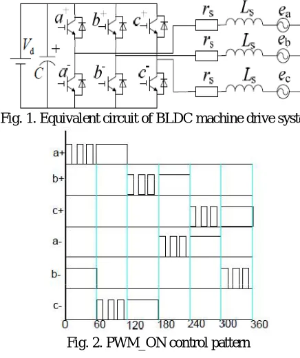
Figs. 1 and 2 show the typical topology of the BLDC machine drive systems and the switching functions. Each switch is operating in the PWM mode for the first 60 degrees and completely turned on for the next 60 degrees. At any time, only two phases are conducting simultaneously.
Fig. 1. Equivalent circuit of BLDC machine drive system
Dept. of EEE, College of Engineering, Trikaripur (CAPE, Government of Kerala), Cheemeni, Kasaragod, Kerala-671313, India
Fig. 3. Six states of inverter in BLDC machine drive
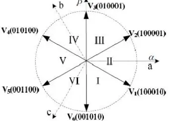
If “1” and “0” are used to represent the on and off statuses of each switch, the power converter operation modes can be described by six active statuses as shown in Fig.3: (100010), (100001), (010001), (010100), (001100) and (001010). Each vector shows the on-off statuses of a+, b+, c+, a-, b- and c-. At any instant two switches are turned on, that is upper leg switch and lower leg switch of two different phases. In the three-phase stationary reference frame, six space voltage vectors V to V can be used to represent the six active statuses as shown in Fig.4. The directions of the voltage vectors in Fig.4 are defined by the switching pattern in Fig.2. Corresponding to the active vectors, the six zero vectors can be written as to V to V . Table I shows the six zero voltage vectors of brushless DC motor drive. Zero voltage vectors are corresponding to the turn-on of only one switch.
Fig. 4. Space vectors in BLDC machine drive
TABLE I. ZERO VOLTAGE VECTORS OF BLDCM DRIVE
Switching sequence
100000 000001 010000 000100 001000 000010
B. Principle of One-Cycle Average Torque Control
ISSN (Online) : 2319 - 8753
ISSN (Print) : 2347 - 6710
I
nternationalJ
ournal ofI
nnovativeR
esearch inS
cience,E
ngineering andT
echnologyAn ISO 3297: 2007 Certified Organization Volume 5, Special Issue 5, April 2016
International Conference on Emerging Trends in Smart Grid Technology - INCETS'16
Organized by
Dept. of EEE, College of Engineering, Trikaripur (CAPE, Government of Kerala), Cheemeni, Kasaragod, Kerala-671313, India
When the electric machine operates in the steady state, the energy stored in the magnetic field reaches a dynamic balance. Thus in each switching cycle, the energy change in the air-gap is zero. Considering the switching cycle is very short, it is reasonable to assume the efficiency of the system remains constant in one switching cycle. Therefore, (1) can be written as:
dW=dW + dW = ηdW (2)
where η is the efficiency of the system. The relationship between the input energy and the average torque T in one switching cycle can be expressed as:
dW =
ηdW =
∆
ηT = kT (3)
where ∆θ is the mechanical angular position change in one switching cycle and k the coefficient defined as ∆ θ/η
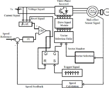
which is constant under the steady state. Based on (3), the electric machine torque variation will reflect as the DC input energy fluctuation. Therefore, the average torque T may be computed by using the energy flowing into the system for each control cycle. The effect of the coefficient k can be counted in the PI control gains. Fig.6 shows the control block diagram using the proposed one-cycle average torque control method to mitigate the torque ripple.
Fig. 6. Control block diagram of torque ripple mitigation using one-cycle average torque control
The output of the speed PI controller is generally taken as the electromagnetic torque command in the traditional motor control. Here, the speed control gains are designed so that the output of the controller is the energy command in each control cycle. As mentioned earlier, the DC bus voltage and current are monitored by sensors. The input energy in one control cycle is calculated by integrating the product of the DC bus voltage and current. Fig.7 shows the control block diagram of one-cycle average torque control algorithm. Fig.8 and Fig.9 demonstrate the operating principle and the flow chart respectively of the one-cycle average torque control algorithm.
Dept. of EEE, College of Engineering, Trikaripur (CAPE, Government of Kerala), Cheemeni, Kasaragod, Kerala-671313, India
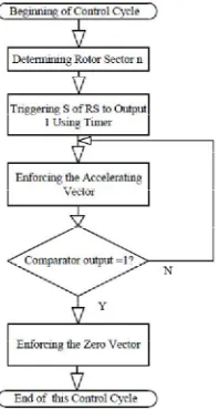
Fig. 8. Flow chart of one-cycle average torque control
At the beginning of each control cycle, a trigger signal is used to activate the integration of the DC input energy. Before the integration value reaches the reference energy, Q of the RS flip-flop is set to be 1 which means the active voltage vector will be applied. When the integration value reaches the reference energy, the energy of the system already meets the command and no extra energy is needed in this switching cycle. Therefore, Q of the RS flip-flop will be set to be 0 which means the zero voltage vector will be applied. Meanwhile, Q is set to1 to reset the integration value. The rotor position will determine which specific active or zero voltage vector will be applied to the electric machine. Table III lists the voltage vector selection for the counter clockwise operation according to the sector definition in Fig.5.
TABLE III. VOLTAGE VECTOR SELECTION TABLE
Rotor Position Sector “n”
Q I II III IV V VI
1
V
V
V
V
V
V
0
V
V
V
V
V
V
As discussed before, the torque ripple will reflect as the fluctuation in the input power or energy. The one-cycle average torque control algorithm suppresses the torque ripple by maintaining the actual input energy in each control cycle constant.
III.SIMULATION RESULTS
In this section the influence of back EMF on the torque ripple is analyzed based on the measured back EMF waveforms of the BLDC machine. Secondly, simulation using the one-cycle average torque control is presented. The torque ripple waveform with ON_PWM switching and PWM_ON switching are compared.
A. Analysis of Torque Ripple Caused by Non-Ideal Back EMF
ISSN (Online) : 2319 - 8753
ISSN (Print) : 2347 - 6710
I
nternationalJ
ournal ofI
nnovativeR
esearch inS
cience,E
ngineering andT
echnologyAn ISO 3297: 2007 Certified Organization Volume 5, Special Issue 5, April 2016
International Conference on Emerging Trends in Smart Grid Technology - INCETS'16
Organized by
Dept. of EEE, College of Engineering, Trikaripur (CAPE, Government of Kerala), Cheemeni, Kasaragod, Kerala-671313, India
(a) (b)
Fig. 11. Currents and back EMF of BLDC machine with (a) ideal back-EMF (b) actual back-EMF
According to (11), with ideal rectangular current, the electromagnetic torque is constant if the machine has an ideal trapezoidal back- EMF, as shown in Fig.11 (a). However, for the machine with non-ideal trapezoidal back EMF, such as the waveforms shown in Fig.10, the electromagnetic torque is not constant when the phase-current is still the rectangular waveform. Fig.11.(b) shows the torque waveform and the frequency of the torque ripple is six times the fundamental component of the back- EMF.
B. Simulation and Analysis
Simulation of the One-cycle average torque control is conducted. A few parameters of the BLDC machine drive systems used in the simulation are listed in Table IV.
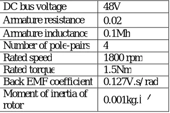
TABLE IV. PARAMETERS OF BLDC MACHINE DRIVE SYSTEM
DC bus voltage 48V Armature resistance 0.02 Armature inductance 0.1Mh Number of pole-pairs 4
Rated speed 1800 rpm Rated torque 1.5Nm Back EMF coefficient 0.127V.s/ rad Moment of inertia of
rotor 0.001kg.
Dept. of EEE, College of Engineering, Trikaripur (CAPE, Government of Kerala), Cheemeni, Kasaragod, Kerala-671313, India
Fig. 12. Operating principle of one-cycle average torque control
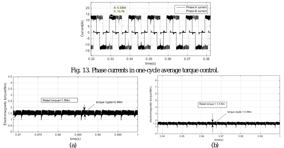
Fig.13 shows the current waveforms of the phases A and B. The peak current is 13.79A and the average current is about 8.7A. The current is not perfectly rectangular. Fig.14(a) shows the electromagnetic torque waveform of the one-cycle average torque controlled brushless DC motor drive with ON_PWM switching. The torque waveform is flat without the arc-shaped ripples. The average torque is 1.5Nm. The torque ripple is mitigated and its magnitude is about 0.4Nm. Fig.14(b) shows the electromagnetic torque waveform of the one-cycle average torque controlled brushless DC motor drive with PWM_ON switching. Here commutation torque ripple is less as compared with the ON_PWM switching.From Fig.14(a) and Fig.14(b) we can see that there are some spikes in the torque waveform in the commutation interval. These are called commutation torque ripples. Here the commutation torque ripple is not considered.
Fig. 13. Phase currents in one-cycle average torque control.
(a) (b)
Fig. 14.Electromagnetic Torque in One-Cycle Average Torque Controlled BLDCM (a) with ON_PWM switching (b) with PWM_ON switching
ISSN (Online) : 2319 - 8753
ISSN (Print) : 2347 - 6710
I
nternationalJ
ournal ofI
nnovativeR
esearch inS
cience,E
ngineering andT
echnologyAn ISO 3297: 2007 Certified Organization Volume 5, Special Issue 5, April 2016
International Conference on Emerging Trends in Smart Grid Technology - INCETS'16
Organized by
Dept. of EEE, College of Engineering, Trikaripur (CAPE, Government of Kerala), Cheemeni, Kasaragod, Kerala-671313, India
calculates the optimal current waveform and uses that as the current command to reduce the torque ripple. The second category uses observers to estimate the stator flux linkage and torque. All these methods need accurate information of the back EMF and rotor position. The concept of one-cycle control is used here to mitigate the torque ripple of BLDCM. In one-cycle control the average value of the switched variable follows its control reference within a switching cycle. In one-cycle average torque control the torque is controlled by controlling the input energy in one switching cycle. Here the average torque in one switching cycle is made constant. This method does not require the information of back EMF and accurate rotor position. Only one voltage sensor and one current sensor are needed to detect the DC bus voltage and current.The operation principle of the one-cycle average torque control algorithm is presented in detail. The flux linkage and electromagnetic torque behaviour in each control cycle is analyzed. It is straightforward to compute the input energy in each control cycle to implement the computation of average torque in a microprocessor. Simulation of One-Cycle control method is evaluated using matlab. Various waveforms are analyzed. The torque ripple is mitigated and its magnitude is about 0.4Nm. Commutation torque ripple with PWM_ON switching is less as compared with the ON_PWM switching.
REFERENCES
[1] J. H. Song and I. Choy, “Commutation Torque Ripple Reduction in Brushless DC Motor Drives Using a Single DC Current Sensor”,
IEEE Trans. Power Electron., vol. 19, no. 2, pp. 312-319, March, 2004.
[2] Guangwei Meng, Hao Xiong and Huaishu Li, “Commutation Torque Ripple Reduction in BLDC Motor Using PWM_ON_PWM Mode”.
IEEE Trans. Ind. Electron., vol. 55, no. 2, pp. 602–609,Feb. 2008.
[3] T. Shi, Y. Guo, P. Song and C. Xia, “A New Approach of Minimizing Commutation Torque Ripple for Brushless DC Motor Based on DC-DC
Converter”, IEEE Trans. Ind. Electron., vol. 57, no. 10, pp.3483-3490,October, 2010.
[4] J. Shi and T. Li, “New Method to Eliminate Commutation Torque Ripple of Brushless DC Motor with Minimum Commutation Time”, IEEE
Trans. Ind. Electron., vol. 60, no. 6, pp. 2139-216, Jun,2013.
[5] S. J. Park, H. W. Park, M. H. Lee and F. Harashima, “A New Approach for Minimum-Torque-Ripple Maximum-Efficiency Control of
BLDC Motor”, IEEE Trans. Ind. Electron., vol. 47, no. 1,pp.109-114, February,2000.
[6] Y. Liu, Z. Q. Zhu and D. Howe, “Direct Torque Control of Brushless DC Drives with Reduced Torque Ripple”, IEEE Trans. Ind. Appl., vol.
41, no.2, pp. 599-608, March/April, 2005.
[7] K. M. Smedley and S. Cuk, “One-Cycle Control of Switching Converters”, IEEE Trans. Power Electron., vol. 10, no. 6, pp.