A Review on Bit Error Rate Detection using
Carrier offset in MIMO-OFDM
Deepanshu Girdhar, Yogesh Juneja
M.Tech Scholar, Department of Electronics and Communication, PDM College of Engineering, Bahadurgarh, Haryana,
India
Assistant Professor, Department of Electronics and Communication, PDM College of Engineering, Bahadurgarh,
Haryana, India
ABSTRACT: OFDM may be combined with multiple antennas at both the access point and mobile terminal to
increase diversity gain and/or enhance system capacity on a time-varying multipath fading channel, resulting in a multiple-input multiple-output (MIMO) OFDM system. This paper discusses the basic introduction to a general MIMO-OFDM system including the block diagram, governing equation, relevant designing parameters and brief analysis of system performance parameters.
KEYWORDS: MIMO-OFDM; BER; PAPR; Channel Capacity;Synchronization, Carrier offset.
I. INTRODUCTION
MIMO is an acronym for ‘Multiple Input Multiple Output’. In this technology, more than one antennais mounted at each end to improve the performance of a communication system. Multiple-input- multiple-output (MIMO) exploits spatial diversity by having several transmit and receive antennas [1]. This arrangement provides significant improvement in the data throughput and link range without increasing the input power and the bandwidth for transmission. On the other hand, OFDM (Orthogonal Frequency Division Multiplexing) is a technique for encoding the digital data on multiple carrier frequencies prior to transmission. The main advantage of OFDM is that it can overcome a lot of transmission losses like narrowband interference, high frequency attenuation, multi-path fading etc. When both of these technologies are combined together, new technique is emerged namely MIMO-OFDM [6],[7].
Figure 1: Block Diagram of MIMO-OFDM
In this block diagram, it is shown that thehigh rate data stream is given to space-time processor where it is converted in to sub-streams through simple multiplexing or space-time coding for OFDM modulation and transmission through different antennas. Then, these space-time processed data streams after passing through OFDM modulators are transmitted through a number of antennas. A suitable technique is adopted for modulation depending upon the channel conditions and other transmission factors like available power and distance of transmission etc. Then, these transmitted data streams are received through a number of antennas at the receiving end. The number of antennas at both the ends may be same or different. Further, after OFDM demodulation, the data is present into its original form for further processing at the receiving end.
II. ANALYSING OF EQUATIONS FOR MIMO-OFDM
As shown in figure 1, space-time processing converts the transmitted symbol or data stream {Sn} into Mt sub-streams {Sk(m)} through simple multiplexing or STC (Space Time Coding) for OFDM modulation and transmission through different antennas. To avoid the inter-symbol interference, usually cyclic prefix is inserted in the signal prior to the transmission. It is basically the extension of the OFDM symbol itself by inserting a part of previous symbol at the beginning of the next symbol.
Let be the complex symbols to be transmitted at the OFDM block, then the OFDM modulated signal can be represented by [2]
where, Δf, and N are the symbol duration, the k is sub-channel space, and the number of sub-channels of OFDM signals
are calculated using above relation respectively. This OFDM signal is transmitted through a number of antennas in a MIMO-OFDM system. If only a multipath of wireless channels is considered and the CP (Cyclic Prefix) is long enough, the demodulated signal at each receiving antenna is a superposition of the signals received from different transmitting antennas and can be expressed as [2]
.
Where , , , and are the received signal vector, transmitted signal vector, noise vector, and channel matrix at the kth sub-channel respectively and are defined as [2]
Xk={xk(1)………..xk(Mr)} (4)
Sk={Sk(1)…………Sk(Mt)} (5) nk={nk(1)…………nk(Mt)}
Hk={Hk(1)………HkMt)}(6)
These are the various mathematical equations to represent the MIMO-OFDM signals in simple as well as in matrix form.
III. CHALLENGES IN WIRELESS MIMO-OFDM SYSTEMS
A. Synchronization
Since in a MIMO system, there are a number of transmitting as well as receiving antennas, hence all of these antennas have to be synchronized prior to the transmission of any kind of data through them. If there is lack of the synchronization then there will be undesired overlapping or destruction of the transmitted data symbols which eventually results in the degradation of the overall performance of the system as a whole.
B. Need of FFT units at the Transmitter & Receiver
Before transmission, the data stream is broken into many small data packets and then all of them are transmitted and then received through a number of antennas. For this procedure, at the transmitter, the IFFT (Inverse Fast Fourier Transform) of the given data has to be carried out which requires an IFFT unit, with the help of which the operation is accomplished. And similarly at the receiving end, the phenomenon (FFT) is carried out for the demodulation and recovery purpose. For all this, IFFT and FFT units are required at the transmitting and receiving ends which increase the overall cost of the system.
C. Sensitivity related Carrier Frequency Offset
Carrier Frequency Offset (CFO) [9] is one of the most common impairments found in a communication system. It is due to the mismatch between the carrier frequencies used by transmitter and receiver of the system. The main cause of carrier frequency offset is the Doppler shift of the channel and the difference between the transmitter and receiver local oscillator frequencies. In MIMO-OFDM systems, CFO destroys the orthogonality between subcarriers and causes inter-carrier interference (ICI). CFO must be accurately estimated and compensated to ensure good performance of a MIMO-OFDM system. For a collocated MIMO-MIMO-OFDM system, periodic training sequences are used to estimate the CFO.
D. High PAPR
Almost all communication systems including MIMO-OFDM are employed with power amplifiers in order to obtain the necessary power level for transmission. To achieve the highest power efficiency, the High Power Amplifiers (HPAs) are operated at or near the saturation region which eventually leads to distortion and introduce inter-modulation products between different subcarriers. In MIMO-OFDM system, a number of high frequency carrier signals are used to transmit a number of narrow-band input signals. Therefore in time domain, a multi-carrier signal is the sum of many narrow band signals. This gives the peak value of the signal higher than average value. The higher value of PAPR reduces the power efficiency of the system. To minimize the value of PAPR, techniques like Selected Mapping (SLM) technique, Partial Transmit Sequence (PTS), Discrete Fourier Transform (DFT) spreading technique and Pulse Shaping technique are used [5].
E. Suitable Modulation Technique
If the data is to be transmitted up to a long distance, then it has to be modulated with some suitable method of modulation. Generally four modulation schemes are used:
Sometimes, it becomes difficult to choose the appropriate modulation technique according to the given channel conditions and other input parameters.
F. Implementation Complexity
As explained earlier, a MIMO-OFDM system has a number of sub-systems with a number of transmitting and receiving antennas. The sub-systems include space-time processor, modulator, demodulator, power amplifiers, IFFT and FFT units at transmitter and receiver respectively. These all increase the complexity and cost of implementation of a MIMO-OFDM system which prove to be a major challenge in its practical implementation.
G. Size of Antenna Array
Although more number of antennas certainly improve the performance of a MIMO-OFDM system by reducing its BER and increasing channel capacity; but it also raises some issues like more power requirements, synchronization and higher value of PAPR etc. Therefore the size of antenna array has to be chosen by keeping all these factors in mind so that there may not be any compromise with the efficiency and fidelity of the MIMO-OFDM system under consideration.
IV.PERFORMANCE PARAMETERS OF A MIMO-OFDM SYSTEM
The performance of a MIMO-OFDM system depends upon a number of factors. There are certain parameters which decide the performance and efficiency of the wireless MIMO-OFDM system. Some of the most important parameters are briefly explained as follows:
A. Input Power (Pin
)
The input power is a primary parameter to decide the performance of a MIMO-OFDM system. The range and efficiency of any system depend on its input power. In a MIMO system, it becomes important to feed all the antennas with the required power according to the type of modulation technique used and path of transmission of user data (or signal).
In order to implement a MIMO communication system, we must first select a particular coding scheme. Most space-time coding schemes have a strong connection to well-known single-input single-output (SISO) coding approaches and assume an uninformed transmitter (UT). Later in the article we discuss space-time low-density parity-check codes, space-time turbo codes, and their respective receivers. Space-time coding can exploit the MIMO degrees of freedom to increase redundancy, spectral efficiency, or some combination of these characteristics [7]. Preliminary ideas are discussed elsewhere [6].
A simple and elegant solution that maximizes diversity and enables simple decoupled detection is proposed in Reference 7. More generally, orthogonal space-time block codes are discussed in References 2 and 3. A general discussion of distributing data across transmitters (linear dispersive codes) is given in Reference 8.
B. Number of Antennas
In a MIMO system, data is transmitted through a number of antennas. If number of antennas are used less then we require lesser power for transmission but there will be more bandwidth transmitted per antenna in this case. So the symbol duration will be less and hence inter-symbol interference (ISI) will be more. In the opposite case i.e. with more number of antennas, the power required will be more but also there will be less interference between the symbols and the complexity of the receiver is reduced.
C. Bit Error Rate (BER)
This is one of the major parameters for end-to-end performance measurement. It is basically the fractional relation between the number of output bits with errors and the total number of bits transmitted and may be defined as:
BER=No. of bits with errors/Total no. of bits
D. PAPR (Peak to Average Power Ratio)
The PAPR is defined as the ratio between maximum power and the average power of the complex pass-band signal. It may be given as [4]:
E. Channel Capacity
It is the maximum amount of information that can reliably be transmitted over any communication channel at any given instant. It is denoted by ‘C’ and can be given as: where B= Bandwidth in Hz; = Signal to Noise Ratio. Channel Capacity of the system increases with increase in SNR as well as with number of antennas in the system. Further, when number of transmitting and receiving antennas is increased in MIMO-OFDM systems, rate of increase in channel capacity also increases.
V.BRIEF ANALYSIS OF MIMO-OFDM SYSTEM PERFORMANCE
TABLE I. Simulation Parameters for MIMO-OFDM System
Sr. No Name of the
Parameter
Description
1. Number of Antennas 4 2. Number of Subcarriers 32
3. Type of Channel Used Rayleigh Channel 4. Modulation Scheme BPSK, QPSK,
16-QAM 5. Pilot Pattern Used Independent
6. Number of Pilot
Symbols
4
7. Number of Channel
Taps
1
8. Start SNR 0 dB
9. End SNR 40 dB
In this section, a brief analysis of the performance parameters obtained by the simulation of a MIMO-OFDM system has been covered. The system parameters considered for this analysis are given in table 1
.
A.BER Analysis of MIMO-OFDM System
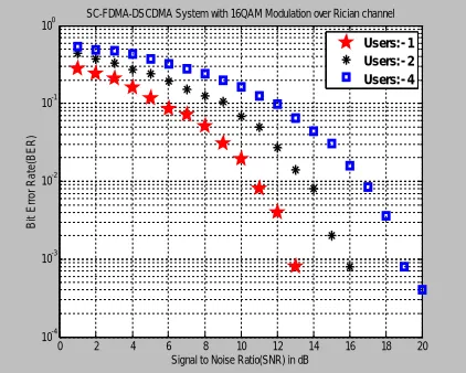
In figure 2, BER performance of a MIMO-OFDM system is analyzed by taking four transmitting and receiving antennas with different modulation techniques
0 2 4 6 8 10 12 14 16 18 20
10-4 10-3 10-2 10-1 100
SC-FDMA-DSCDMA System with 16QAM Modulation over Rician channel
Signal to Noise Ratio(SNR) in dB
B it E rr o r R a te (B E R ) Users:- 1 Users:- 2 Users:- 4
In fig.2, Rician channel is used for comparison with different modulation techniques. We can see in above fig.2 that at particular 10-3 BER, SNR is 12.8dB when user is 1; SNR is 15.7dB when users are 2; SNR is 18.8dB when users are 8. It has been observed that there is constantly increase in SNR value i.e. 3dB when users are increasing.
B. PAPR Analysis of MIMO-OFDM System
The value of PAPR of a communication system has to be minimum for better power efficiency. The PAPR performance of any communication system is measured in terms of Complementary Cumulative Distribution Function (CCDF) which is defined as the amount of time spent by a waveform at (or above) a particular power level. CCDF is probabilistic in nature and may be mathematically given as:
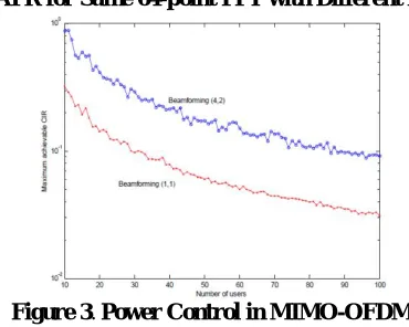
Figure 3. CCDFs of PAPR for Same 64-point FFT with Different Modulation Techniques
Figure 3. Power Control in MIMO-OFDM
which means the probability of PAPR being greater than a particular value of PAPR that is PAPR0. Figure 3 shows the CCDFs of PAPR with same FFT size i.e. 64-point with different modulation techniques (QPSK, 16QAM). As we go on lower modulation to higher modulation technique, PAPRincreases which means high power amplifier is required at receiver side.
VI. CONCLUSIONS
antenna array. Further, the BER and PAPR performance analysis of MIMO-OFDM systems has been covered in this paper. Simulation results prove that BPSK and QPSK modulation schemes provide better BER response as compared to 16-QAM.
REFERENCES
[1]Helka Määttänen ,“MIMO-OFDM” system design survey on www.comlab.hut.fi/opetus/333/2004_2005_slides/MIMO OFDM_text.pdf [2] T. Hwang, C. Yang, G. Wu, S. Li, G. Y. Li, “OFDM and its wireless applications: A survey”, IEEE Transactions on Vehicular Technology, Volume: 58, Issue: 4, Page(s): 1673 – 1694, May 2009
[3] M. Agrawal and Y. Raut, “BER analysis of MIMO-OFDM system for AWGN & Rayleigh fading channel”, International Journal of Computer Applications, Volume 34-Number 9, 2011.
[4] Y. S. Cho, W. Y. Yang, MIMO-OFDM Wireless Communications with MATLAB, John Wiley & Sons Publication, 2010
[5] M.V.R. Vittal, “Performance enhancement of OFDM signals using PAPR reduction techniques and the comparison of their performance”, International Journal of Computer Applications, IJCA Journal, Volume 41 - Number 19, 2012
[6] H. Yang, “A road to future broadband wireless access: MIMO-OFDM-Based air interface”, IEEE Communications Magazine, Volume: 43 , Issue: 1, Page(s): 53 – 60, Jan. 2005
[7] M. Jiang and L. Hanzo, “Multiuser MIMO-OFDM for next generation wireless systems”, Proceedings of IEEE, Volume: 95, Issue: 7, page(s): 1430-1469, July 2007
[8] N.B. Sinha, M.C. Snai, M.Mitra, “Performance enhancement of MIMO-OFDM technology for high data rate wireless networks”, International Journal of Computer Science and Application, 2010