www.ijiset.com
Wideband Gap Coupled Microstrip Antenna using RIS
Structure
Pallavi Bhalekar1 and L.K. Ragha2
1 Electronics and Telecommunication, Mumbai University,
Mumbai, Maharashtra, India
2
Electronics and Telecommunication, Mumbai University, Mumbai, Maharashtra, India
Abstract
This paper presents a wide band gap coupled microstrip patch antenna. The microstrip antenna (MSA) is placed 1.5mm above ground plane and fabricated on FR4 substrate and to improve the efficiency and bandwidth of the antenna. A reactive impedance surface (RIS) is fabricated on the bottom side of FR4 substrate consisting of 11×7 array of 4 mm square patches with inter-element spacing of 1 mm. Bandwidth of antenna is improved by using RIS which reduces the coupling between the ground plane and MSA patch. Gap coupled parasitic patches are places at the both radiating edges of fed patch of MSA fabricated on a FR4 layer. The VSWR is < 2 is obtained over 4.915 - 6.243 GHz, which covers bandwidth of 1.328 GHz and 5.15-5.35 GHz ISM, 5.725 - 5.875 GHz ISM WLAN frequency band. The antenna structure provides VSWR < 2 dB and 75 % antenna efficiency. A gap coupled MSA with RIS is fabricated and tested. The measured results satisfy with the simulation results.
Keywords: MSA; Gap coupled; Parasitic patches; Reactive impedance Surface.
1. Introduction
Microstrip patch antennas are widely used in satellite communication, military purposes, GPS, mobile, wireless communication etc. due to its compact shape and light weight, less complexity and ease of manufacturing. MSA have drawbacks like low gain, narrow bandwidth, low efficiency. One of the main limitation with MSA is its low impedance bandwidth due to its resonant nature [1-3]. Many methods and structures have been recently proposed to enhance the bandwidth and gain of antenna.
Bandwidth enhancement can be achieved by using thick structures, square slot techniques, defected ground structures [4-6]. The structure of microstrip patch antenna where only single patch is fed and other patches are coupled parasitically. The coupling between the parasitic patch and resonating patch is realized by using small gap between them. Two parasitic patch of same dimensions are placed along both radiating edges of fed patch with small gap between them.
By adding parasitic patch along the fed patch increases bandwidth as well as gain of an antenna [7-8]. With this the size of antenna also increased. To miniaturize the size of antenna and to enhance the bandwidth of an antenna RIS structure is used in antenna. Antenna structures with RIS have been reported [9-12]. The RIS in antenna design is made up of the two-dimensional square metal patches. An array of uniform square patches with equal spacing are fabricated on the bottom side of substrate below MSA. The RIS also decreases the coupling between the ground plane and antenna structure designed on it. Therefore, when RIS structure is designed in antenna it provides wide bandwidth, compact size and improves radiation efficiency [9-12].
Compact size MSA with various structure of fed patch Asymmetric/symmetric slotted on RIS for circular polarization has been reported [13].
In this paper, a suspended gap coupled microstrip patch antenna with RIS surface is designed and fabricated. RIS surface is used to increase the bandwidth of an antenna to obtain uniform gain over this bandwidth. RIS reduces the coupling between the ground plane and microstrip antenna and thus improves its bandwidth. Following section contain details of the antenna geometry, design theory, simulated and measured results on infinite and finite ground.
2. Antenna Geometry and Design Theory
www.ijiset.com IE3D 14.0 simulator [14]. The structures with only gap
coupled MSA, with and without RIS layer are designed and simulated. Suspended gap coupled MSA without RIS surface provides return loss, S11 < -9.5dB and VSWR, < 2 dB is obtained over 5.294 - 6.623 GHz and hence impedance bandwidth of 1.3 GHz is obtained and provides uniform gain of 8.85 dBi over this bandwidth. For Suspended gap coupled with RIS layer provides return loss, S11< -9.5dB and VSWR, < 2dB is obtained over 4.964 - 6.383 GHz and hence impedance bandwidth of 1.4 GHz is obtained and provides uniform gain of 8.65 dBi over this bandwidth. Since RIS reduces the interaction between ground plane and substrate. RIS layer also improves the bandwidth of an antenna. RIS layer also miniaturises the dimensions of MSA patch as well as radiating patches. Dimensions of MSA patch and radiating patches without RIS layer are 16.5 ×15.5 mm and 14 × 15.5 mm respectively. Dimensions of MSA patch and radiating patches with RIS layer are 16.5 ×15.1 mm and 14 × 15.1 mm respectively. The gap between MSA patch and radiating patches is 5 mm. The structure with RIS has slightly lower gain despite provides uniform gain over 4.79-5.955 GHz frequency range than the structure without RIS.
(a) Geometry of proposed antenna
(a) Gap coupled MSA
(b) Reactive Impedance Surface
Fig. 1 Geometry of antenna structure
3. Simulation Results
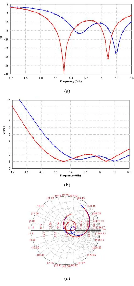
Return loss, VSWR and impedance variation for the structures of gap coupled microstrip antenna with and without RIS layer on Infinite ground plane are shown in Figure 2, and gain variation of these structures are shown in Figure 3.
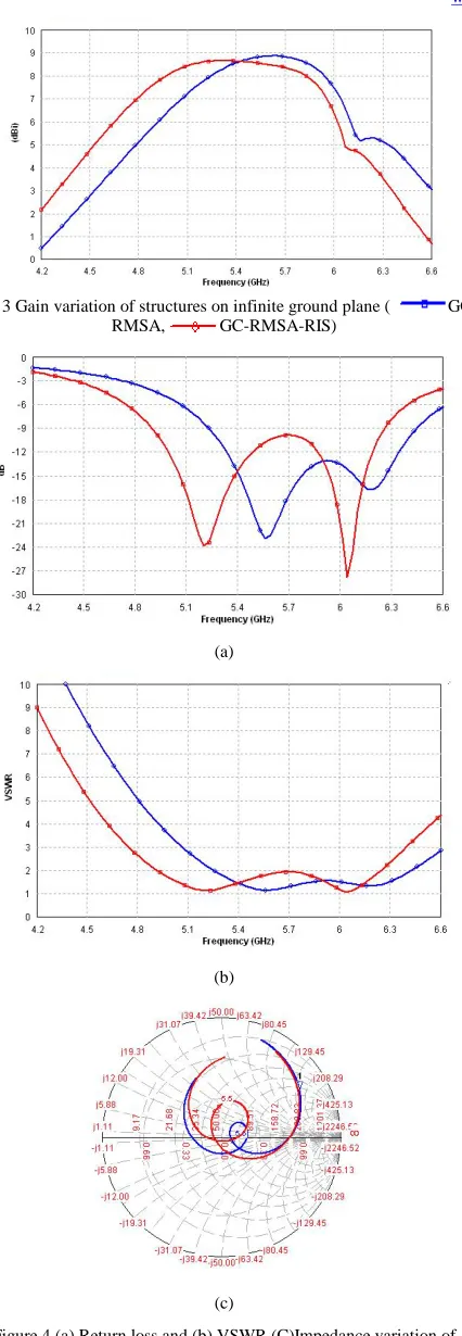
Suspended gap coupled MSA with and without RIS provides return loss, VSWR and impedance variation of structures are shown in Figure 4. Radiation patterns at 5.2 GHz and 5.8 GHz on finite ground are shown in Figure 5. Gain variations of structures are shown in Figure 6.
(a)
(b)
(c)
Fig. 2 (a) Return loss (b) VSWR and (c) Impedance variation of
structures on infinite ground plane ( GC-RMSA,
www.ijiset.com
Fig. 3 Gain variation of structures on infinite ground plane (
GC-RMSA, GC-RMSA-RIS)
(a)
(b)
(c)
Figure 4 (a) Return loss and (b) VSWR (C)Impedance variation of
structures on finite ground plane ( GC-RMSA,
GC-RMSA-RIS)
(i) GC-MSA
(ii) GC-MSA-RIS
(a) 5.2 GHz (b) 5.8 GHz
Fig. 5 Radiation pattern of Gap coupled MSA structures on finite ground
at 5.2 GHz and 5.8 GHz( Eθ Eφat φ = 0° and
Eθ Eφat φ = 90°)
Fig. 6 Gain variation of structures on finite ground plane (
GC-RMSA, GC-RMSA-RIS)
4. Effect of Finite Ground Plane
www.ijiset.com provides gain of 10.07 dBi. For structure with RIS provides return loss, S11 < -9.5dB and VSWR, < 2dB is obtained over 4.915 - 6.243 GHz and hence impedance bandwidth of 1.328 GHz is obtained and provides uniform gain of 9.79 dBi over this bandwidth.
5. Fabrication and Measured Results
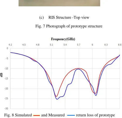
A prototype structure of gap coupled MSA with RIS is fabricated and tested. The size of fed patch is 16.5 mm × 15.5 mm and size of both the parasitic patches is 14 mm × 15.5 mm. The gap between fed patch and parasitic patch is 5 mm are fabricated on FR4 layer with thickness of 1.59 mm is placed at a height of 1.5 mm from 80 mm × 64 mm ground plane. The photograph of prototype gap coupled MSA with RIS structure is shown in Figure 7. Return loss is measured using Agilent 9916A network analyzer. The measured and simulated results are shown in Figure 8. There is good match between the measured results and simulation results. The variation in measured and simulation results may be due to alignment error in substrate and superstrate layer, fabrication error, error in feed position.
(a) Gap coupled MSA with RIS structure
(b) Gap coupled MSA -Top view
(c) RIS Structure -Top view
Fig. 7 Photograph of prototype structure
Fig. 8 Simulated and Measured return loss of prototype
structure
6. Conclusion
Wide band antenna structure using gap coupled MSA with RIS is designed. Bandwidth of antenna is improved by using parasitic patches and RIS structure. The structure offers uniform gain of 9.79 dBi, bandwidth of 1.328 GHz and VSWR < 2 dB over the band of 4.915 - 6.243 GHz. The antenna pattern has antenna efficiency > 75 and F/B lobe ratio > 20 dB. The structures can be a good candidate for wireless communication systems.
References
[1] G. Kumar and K P. Ray, Broadband Microstrip Antennas, Norwood, MA Artech house, 2003.
[2] D. M. Pozar and D. H. Schaubert, Microstrip Antennas: The Analysis and Design of Microstrip Antennas and Arrays, John Wiley and sons Inc. USA, 1995.
[3] Constantine A. Balanis, Antenna Theory and Design, 3rd Edition, John Wiley and sons Inc. USA, 2005.
www.ijiset.com
[5] V.P Patil, “Enhancement of Bandwidth of rectangular Patch,” International Journal of Engineering Sciences & Emerging Technologies, vol. 3, no. 2, pp. 477–481, 1-12, Oct.2012, ISSN 2231-6604.
[6] L.H Weng, Y.C Guo, X.W Shi, X.Q Chen, “An overview on Defected Ground Structure”. Progress in Electromagnetic Research B, vol. 7, 2008, pp. 173–189
[7] Rupesh Raut, Kavita Talandage, “Bandwidth and gain enhancement of rectangular MSA by using parasitic patch and capacitive feeding technique for wideband application,” IEEE antennas and wireless propagation letters, vol. 5, no.8, pp. 393-396, 2015.
[8] T.M. Au, K.M. Luk, “Effect of parasitic element on the characteristics of antenna” IEEE Trans. Antennas Propag., vol. 39, no. 8, Aug. 1991, pp. 1247–1251.
[9] K. Buell, D. Cruickshank, H. Mosallaei, and K. Sarabandi, “Patch antenna over RIS substrate: A novel miniaturized wideband planar antenna design,” Proc. IEEE Antennas Propag. Soc. Int. Symp., 2003, pp. 269–272.
[10] H. Mosallaei and K. Sarabandi, “Embedded-circuit and RIS meta-substrates for novel antenna designs,” Proc. IEEE Antennas Propag. Soc. Int. Symp., 2004, pp. 301–304.
[11] H. Mosallaei and K. Sarabandi, “Antenna miniaturization and bandwidth enhancement using a reactive impedance substrate,” IEEE Trans. Antennas Propag., vol. 52, no. 9, Sep. 2004, pp. 2403–2414.
[12] Kamal Sarabandi, Amelia M. Buerkleand Hossein Mosallaei, “Compact Wideband UHF Patch Antenna on a Reactive Impedance Substrate,” in IEEE antennas and wireless propagation letters, Vol. 5, pp. 503-506, 2006.
[13] Kush Agarwal, Nasimuddin, and Arokiaswami Alphones,” RIS-Based Compact Circularly Polarized Microstrip Antennas,” IEEE transaction on antennas and propagation, Vol. 61, No. 2, pp. 547-554, February 2013.
[14] IE3D Release 14.0, Zealand Software Inc. Fremont, USA.
Pallavi Bhalekar born in India 1991. She received her B.E degree in EXTC engineering (2012). She is pursuing her master of engineering in EXTC from Terna engineering college, Nerul, Navi Mumbai.