Improving the Smart Distribution Grid
Dr S N Saxena
Ex-General Manager, Bharat Heavy Electricals Ltd, R&D, Hyderabad, India, 2001, OL-1, ELDECO UTOPIA, Sector-93A, Noida, U.P.-201304, India
Abstract
Single-phase loads in premises of domestic and commercial consumers produce unbalanced currents and poor power factor in three-phase distribution lines. Converters connecting solar photovoltaic and stationary battery energy storage units to grid also inject voltage or current harmonics in lines. Long low-voltage distribution lines give poor voltage regulation for consumers. In order provide quality power to consumers, distribution companies must provide compensating units at suitable locations. Distribution static compensators can be employed to improve voltage profiles in system. Distribution companies must also reduce line power losses and voltage drops by changing to higher voltage distribution system. Distribution companies must educate to the house owners for installing solar photovoltaic power panels on their rooftops to the maximum extent. Simple explanation of virtual power plants has been given. The discussion summarizes the steps to be taken by the planning engineers for improving the smart distribution grid.
Keywords: Smart Distribution Grid, Distribution Static Compensator, High Voltage Distribution System, Solar PV Power, Virtual Power Plant
1. Introduction
A paper on smart distribution grid had given details which are required for a distribution engineer when planning to make a distribution area “Smart”, also containing information for educating the domestic, commercial and industrial consumers [1]. The present paper gives the suggestions for further improvement of the smart distribution grid.
Single-phase loads in the premises of domestic and commercial consumers create unbalanced currents at the three-phase distribution lines and also give poor power factor. Both these effects result in higher line currents, giving higher line power losses and higher voltage drops in the distribution lines. Further, the converters connecting solar photovoltaic (PV) and stationary battery energy storage units to the grid also produce voltage or current harmonics in the grid. All these require improvements by the installation of compensating systems at many locations in the distribution area. Section 3 discusses all these effects and how these can be overcome by the application of one or two “Distribution Static Compensators” (DSTATCOMs).
Presently, most of the distribution systems are based on long three-phase 415 distribution lines in a colony, which are fed with overhead three-phase 11 kV distribution lines. All these are giving higher line power losses and increased line voltage drops (resulting in poor voltage regulation for the consumers). In order to improve this status in large / metro cities, it is essential for distribution companies (DISCOMs) to change the system using high voltage underground cables and running the three-phase 11 kV distribution lines to as close as possible to the consumers.
To support the plans of Government of India (GoI) to increase the power generation by renewable energy sources, some ideas have been given in Section 5 regarding the roles DISCOM can play in encouraging the people and organizations: (a) to install solar PV panels on rooftops and in the open space to the maximum extent; and (b) to take advantage of vehicle-to-grid (V2G) connection for supplying energy to vehicle-to-grid when their cars are idle. At the end, simple explanations have been given in Section 6 on virtual power plant, followed by “Discussion” in Section 7.
2. Review of Literature
[3]. Reference [4] by Gungor et al has discussed potential applications and also the communications requirements of the smart grid. These two papers would of interest to the readers for details related to the communication technologies in the smart grid.
3. Applications of DSTATCOM in Smart Distribution Grid
3.1 principle of DSTATCOM
Static compensators (STATCOMs) of hundreds of MVAr capacities have been employed for the last two decades in extra high voltage (EHV) transmission systems for improvements in their performance [5]. Earlier, the STATCOM used thyristor as the device, but subsequently, gate turn-off thyristor (GTOs) or integrated gate-commutated thyristor (IGCT) has been employed. Although its application can be of immense help in solving the situations arising in the EHV systems, the high initial cost of STATCOM has restricted the number of units existing all over the world. Therefore, the power system engineers have gone for the other simple solutions.
The application of “Distribution Static Compensator” (DSTATCOM) to distribution system is a recent development, made possible due to the large-scale production of high voltage, high current insulated gate bipolar transistors (IGBTs) by many suppliers being offered at low prices [6].
The main component of DSTATCOM is a three-phase voltage source converter (VSC) (with a capacitor-C on DC side) connected to the distribution grid (as shown in Fig.1) through a transformer of high reactance (of about 12 per cent).
Fig.1 Schematic of DSTATCOM
The operation of DSTATCOM gives complete control of the magnitude and phase of the compensating current (IComp)
injected into each phase. It can be used for: (a) dynamic voltage control; (b) reactive power compensation; (c) harmonic compensation; and (d) unbalanced current compensation. The control of VSC can adjust the injected compensating current (IComp) in such a way that these compensating currents can give the balanced sinusoidal currents (IGrid) in the distribution
lines in the grid.
The same hardware can perform any of the above mentioned four functions. Only the control software has to be developed for the type of duty. Therefore, DISCOM can order a few units and place those at the different locations in distribution area as per the required function. A brief discussion of each of the above mentioned compensations is given below.
3.2 Compensation of Unbalanced Line Currents
become (1.1)2 = 1.21 times. Unbalanced line currents would result in unbalanced three-phase voltages in lines, which would give additional heating and noise in three-phase induction motors (connected to these lines and being used in small-scale industries). Therefore, DISCOM must provide DSTATCOMs at a few locations to have the balanced line currents in the distribution system.
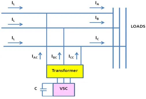
Figure 2 shows the schematic of DSTATCOM designed for compensation of unbalanced line currents. The currents IA, IB
and IC are unbalanced currents caused by loads of domestic and commercial consumers. The controls of VSC injects
compensating currents [IAC, IBC and ICA], so that the currents (IL) in the three distribution lines become balanced.
Fig.2 Schematic of DSTATCOM for compensation of unbalanced line currents
3.3 Compensation of Poor Power Factor
The industrial consumers maintain a power factor (PF) of more than 0.9 at their terminals of receiving substation. This is because the industrial tariff has a penalty component for the PF of less than 0.9 and a reward component for the PF of more than 0.95. The industries with a power consumption of 1 MW or lower employ switched static capacitors to bring the overall average PF in the above range. However, large industries are going for more improved equipment [5].
The domestic and commercial consumers use single-phase loads having low PF, resulting in low PF (of the order of 0.6 – 0.7) in the distribution lines. The tariff for domestic and commercial consumers consists of a fixed amount (as meter charges) and a portion corresponding to the total energy (kWh) consumed in that month. For a given kW load at the nominal voltage, the low PF gives higher line currents, resulting in higher line power losses and higher voltage drops. For example, for the same power consumption and voltage, as compared to a PF value of 0.9, a PF of 0.6 gives increase of line currents by (0.9 / 0.6) = 1.5 times, resulting in increase in line power losses by (1.5)2 = 2.25 times and increase in line voltage drop by 1.5 times. Therefore, DSTATCOMs must be provided at a few locations (as per requirement), so that the power factor of line currents is about 0.95 at most of the locations in distribution system. In the schematic shown in Fig.2, let us assume that the line currents IA, IB and IC are balanced but have poor PF, containing large inductive component (consuming lagging
reactive volt-ampere). Then, the control of VSC injects compensating capacitive currents (IAC, IBC and ICC; supplying
leading reactive volt-ampere) for compensating the inductive currents of loads, resulting in the improved PF of line currents (IL).
3.4 Use of Two DSTATCOMs for Simultaneous Improvement of Two Parameters
be improved substantially. The control of VSC-1 can be set only for PF compensation, so that the PF of line currents is about 0.95. The control of VSC-2 can concentrate only for compensation of the unbalanced line currents.
Fig.3 Use of two DSTATCOMs in distribution system
3.5 DSTATCOM as Dynamic Voltage Regulator
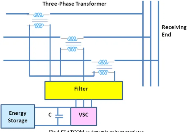
For supplying quality power to the consumers, the voltage must be maintained at the nominal value. If the voltage is higher or lower, then the DSTATCOM (shown in Fig.4) can perform dynamic voltage regulation at the location. For this, three numbers of single-phase transformers are used; with primary winding of each transformer connected in series in each line; and star-connected secondary windings connected to VSC. The control of VSC injects the desired series voltages in three distribution lines to get the nominal voltage at load terminals (receiving end). A filter is connected on AC side of VSC so that only pure sinusoidal voltages are applied to the three lines.
Fig.4 STATCOM as dynamic voltage regulator
3.6 Effects of Solar PV Converter on Distribution System
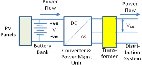
always from DC side to three-phase AC distribution system through a DC-to-AC converter (inverter). The conversion of DC voltage to three-phase AC produces voltage harmonics on the AC side. The line voltage VAB (Fig.5) contains the
fundamental (50 Hz) component and a series of voltage harmonics (odd or even multiples of 50 Hz). The frequencies and magnitudes of voltage harmonics depend upon the method of control. In modern pulse-width-modulation (PWM)-controlled inverter, the control tries to reduce the voltage harmonics. But with millions of inverters (with solar PV panels) in a city on rooftops, particularly the large capacity inverters with PV panels on building of the government / public / private sector organizations, the total generated voltage harmonics may be quite substantial. Such a three-phase supply with voltage harmonics would cause problems to the three-phase loads operating on this supply. Therefore, sensors must be installed at many locations in the grid for evaluation of these voltage harmonics and, if necessary, these must be compensated by using DSTATCOMs placed at a few locations to reduce their effects on communication circuits and some sensitive loads.
Fig.5 Schematic of PV panel and battery bank connected to distribution system
3.7 Effects of Converter of Stationary Battery Energy Storage on Distribution System
Figure 6 shows connection of stationary battery energy storage to the distribution system. At the first look, it appears to be similar to the schematic given in Fig.5. But, the absence of PV panels makes a difference in the operation of converter. When the battery bank is supplying power to grid, the behavior shown in Fig.6 (a) is the same as that in Fig.5 and the converter injects voltage harmonics on three-phase AC lines.
Fig.6 (a) Stationary battery bank supplying power to distribution system
three-phase AC to DC generates current harmonics in the AC supply lines. As shown in Fig.6 (b), the line currents IA, IB and IC
will contain fundamental (50 Hz) component and a series of current harmonics (odd or even multiples of 50 Hz). The frequencies and magnitudes of the current harmonics would depend upon the control philosophy, but it would be quite substantial and necessitates the installation of passive filters (using tuned R-L-C components) or active filters (using DSTATCOMs).
Fig.6 (b) Charging of stationary battery energy storage unit from distribution supply
4. Improved Distribution System
4.1 Use of Higher Distribution Voltage
The distribution power losses in India are higher because of technical and non-technical causes. The technical reasons include use of overhead lines and distribution at lower line voltage. DISCOM lays three-phase 11 kV distribution lines, with each line terminated at large capacity three-phase 11 kV / 415 V distribution transformers at a few locations. Most of the distribution lines are of three-phase 415 V running up to the consumers’ panels. This arrangement gives increased distribution power losses and chances of non-technical power losses due to theft (mostly by hooking). Therefore, it is necessary to improve the system by the use of high voltage (33 kV) distribution lines [8, 9]. The three-phase 33 kV / 11 kV distribution transformers of lower capacity must be installed at many locations and power supply to the consumers up to their distribution transformers must be done through three-phase 11 kV overhead lines or underground cables, from which the chances of theft becomes nil. The advantages of this system are as follows.
• Due to the use of three-phase 33 kV system for most of the distribution areas and then with three-phase 11 kV lines going up to consumers premises, there is considerable reduction in the distribution power losses due to reduced line currents. Also, the arrangement does not give any chance of power theft by hooking.
• The reduced line power losses would result in reduced loading of the consumers’ distribution transformers and also the substation transformer.
• The use of three-phase 33 kV and 11 kV distribution systems would reduce the voltage drops in distribution lines and thus improve the voltage profile at most of the locations in the area.
• In the new arrangement, as one three-phase 11 kV / 415 transformer feeds lesser number of consumers, the fault in the transformer would give power outage only to a limited number of consumers.
4.2 Use of Indoor Substations
Today most of the three-phase 33 kV / 11 kV transformers and the associated components are located in outdoor substations. The equipments in outdoor substation work at higher ambient temperatures in India, particularly in summer period. Therefore, even with loading of less than the full load, the transformer temperature is higher, giving higher copper losses which would further increase the operating temperature. Also, the outdoor substations are subjected to dust, rain, storm etc, affecting the insulators which might fail due to flashover. The outdoor substation has chances of failure of equipment due to lightning strikes. During storms, the poles and conductors might collapse, resulting in interruption of supply to large area and requiring long time for restoration of supply. Further in the outdoor substations, the bare conductors must be provided with adequate clearances; resulting in substation area becoming large. These days, there is scarcity of land and also land prices are higher. Therefore, attempts must be made to avoid the outdoor substations.
The trend now is to use SF6 “Gas-Insulated Substations” (GIS), which are compact, modular and housed indoor [9, 10]. The
space required for GIS and its installation time are about one-third of that required for outdoor air-insulated substation (Fig.6).
Fig.6 Gas insulated substation
The incoming and outgoing supplies to GIS are through underground cables. Therefore, these substations are not affected by atmospheric conditions. SF6 is inert, non-inflammable, non-poisonous and very stable gas and can work up to a temperature
of 500oC. Due to these properties, the GIS (containing SF6 gas-insulated circuit breaker, isolator, disconnecting switch etc)
have negligible maintenance for many years. The high dielectric strength of SF6 gas permits smaller clearances and hence
compact size of substation. Therefore, in most of the cities, where getting land for new substations is difficult and land prices are going up, DISCOM must go for increased use of indoor GIS. Due to totally enclosed system, GIS can have remote operation, reducing the manpower requirement. The initial cost of GIS is higher; but because of increased reliability, low space requirement, reduced manpower and negligible maintenance for many years, the cost gets recovered in a few years.
A point worth mentioning is that the indoor GIS must be located preferably in a separate building. In case the indoor GIS is required to be housed in a multi-story building, then it must be located in the ground floor only and not in the basement. This is because of bad experience of basement getting flooded with water in case water enters the building during heavy rains, making the substation inoperable in that situation.
4.3 Using Back-up Supply in Substation
battery energy storage with DC-to-AC converter (inverter) must be kept ready for emergency operation. Also if the battery storage is of MW level, then it can also supply the emergency services in that distribution area. This battery storage along with solar PV power (both on rooftops and in open space of consumers and government buildings) existing in the distribution area can be of a great help in case of failure of incoming power supply to the substation.
5.
Educating the Consumers Regarding Distributed Generation
5.1 Increased Installation of Rooftop Solar PV
For climate change mitigation, the Government of India (GoI) has planned to install 175 GW of renewable energy sources (RES) by 2022 [11]. In most of the crowded metro cities, it would be difficult to find open space for installation of wind turbines or solar PV panels of MW order in open space. Therefore, RES in metro and large cities will mostly be rooftop solar PV panels on the buildings of government and public / private sector organizations / institutions. GoI would also like the house owners and the gated-community type apartments to install solar PV panels on the rooftops to the maximum extent. For this, DISCOM must play an important role in educating the consumers, as given below.
• Energy produced from solar PV panels has negligible running and maintenance cost. The maintenance of system includes daily cleaning of the solar PV panel surface using water spray, which the consumer must do regularly to get the maximum power production.
• The solar PV panels must receive maximum sunlight during daytime. The consumers must take care to see that there are no shadows of the tall trees (around the building) falling on the panels; if so, those tree branches must be cut periodically.
• The initial cost of solar PV system is high. Therefore, there are schemes of the Central and State Governments available to support RES through subsidies. DISCOM must educate the consumers about the schemes, so that those subsidies can be availed of by the consumers to have the reduced initial cost. In this way, many consumers would come forward for installation of solar PV panels on rooftops in their premises.
• The PV system would always have lithium-ion battery bank connected to it (Fig.5). The battery bank has a life which is shorter than that of the PV panels. Therefore, there will be a requirement to replace the battery bank after expiry of its life, for which the consumer must plan for the fund.
For feeding the excess power from solar PV to grid, the consumer must be educated to avail of the net metering scheme. This will reduce the monthly energy bill of consumer.
5.2 Vehicle-to-Grid Connection of Personnel Electric Cars
Most of the literatures on smart grid discuss various advantages and the other effects of application of vehicle-to-grid (V2G) technology to the system. V2G can be of immense help in meeting the peak power requirement of DISCOM [12, 13]. However for this, various aspects of electric vehicles (EVs) must be considered, as discussed below.
Electric bus (e-bus) has a battery bank of large capacity. But, the e-buses will be mostly running on their routes during day time and will not be any help during the period of peak demand. Similarly, electric taxis (cabs) will also be moving with passengers in the city during day time and cannot be considered for V2G operation.
Therefore, only personnel electric cars (e-cars) will be of help to DISCOM. Large / metro cities have millions of registered cars (mostly run on petrol or diesel). For example, Delhi National Capital Region (Delhi NCR, which includes some areas of nearby States of Uttar Pradesh and Haryana along with the capital Delhi) had more than 3 million cars in 2017. With the plan of GoI to have 30 per cent EVs by 2030 and only EVs to be registered after that, there will be gradual increase of e-cars over the next 11 years. Therefore, DISCOM can plan to make use of V2G with the help of personnel e-e-cars.
• If 3 or 4 employees living nearby opt for car-pooling for going to the offices, then only one car will be used on a particular day and the remaining idle e-cars (in house garages) can be used for V2G.
• If office is providing charging facilities for the employees, then the top-up of lithium-ion battery bank of e-car can be done by an employee in about one hour and the e-car can have V2G for the remaining hours in office.
• With time-of-the-day tariff available to the domestic consumers (having reduced energy charges during night time when the battery bank will be charged), the consumer will like to feed the energy to grid (by net metering) during day time to reduce his monthly energy bill. Even the commercial consumers after reaching their establishment will be able to give energy to DISCOM during day time and reduce his energy bill of the establishment through net metering. Thus, V2G is a “Win-Win” situation for both consumers and DISCOM.
For the use of V2G as per the requirement of DISCOM, the car battery must have energy management unit, which can receive signal from the distribution control room along with “OK Use V2G” permission by the car owner.
6. Virtual Power Plant
Reference-[2] has given good concepts on virtual power plant (VPP). Similarly, there are many good technical literatures on this subject explaining both operational and energy market benefits [14]. Based, on the understanding of VPP by the author,
simple explanations of VPP are given below.
• VPP is a concept for optimum utilization of the available resources. It is not any physical power plant. It is the next step after realizing the “Smart Distribution Grid” and is required to be planned in advance (with the required investment) along with the planning of smart distribution grid. The main thinking behind VPP is to connect and manage the variability of renewable energy sources (RES, both solar PV and wind-electric power generations) in the distribution system.
• As the power generation capacity by RES is increasing, it was considered to have aggregation of energy generation, energy storage and other loads for a better management of variability of RES with the main aim of
providing 24 x 7 reliable power supplies to all the consumers.
• VPP would make use of the two-way communication facilities already available between the different components (operation controllers of solar PV or wind power units, consumers’ smart meters, control centre of distribution area, etc) in the smart distribution grid for the desired functions mentioned above.
• For the management of VPP, three would be a necessity to have a new specialized player, called the aggregator. This new “aggregator” would become necessary if VPP is required to manage two or more distribution areas, each having large capacity of distributed energy sources. However, if VPP is required to manage only one distribution system, then the existing DISCOM (which is already managing and controlling the distribution) will be working as aggregator.
However, implementation of VPP requires huge expenditure for its efficient and desired control of the system.
7. Discussion
The distribution company must provide 24 x 7 “Quality” supply to all its consumers. The components of “Quality” in a distribution system are: (a) voltage within permissible limits; (b) the voltage waveform very near to sinusoidal (absence of voltage harmonics); and (c) balanced three-phase voltages. Therefore, the smart distribution grid must have sensors at many locations in the area to ensure the above. If there are deviations in any one or more of the above, then compensating systems must be provided at suitable locations.
concept has been given in this paper about the application of two DSTATCOMs for simultaneous compensations of two parameters (say unbalanced currents and poor power factor).
Discussions have been given here regarding the necessity of planning engineers going for high voltage distribution systems for improvement of the smart grid. Also, simple explanations have been given on virtual power plant, so that operating engineers can take care of variability of renewable energy sources and for marketing their energy outputs.
References
[1] S.N.Saxena, “Smart distribution grid and how to reach the goal”, International Journal of Smart Grid, Vol.3, No.4, 2019, pp.188-200. [2] Edited by Nouredine Hadjsaid and Jean-Cloude Sabonnadiere, Smart Grids, 1st ed.; John Wiley, USA, 2012.
[3] Ataul Bari, Jin Jiang, Walid Saad, and Arunita Jaekel, “Challenges in the smart grid applications: an overview”, International Journal of Distributed Sensor Networks, vol. 2014.
[4] V. Cagri Gungor, Dilan Sahin, Taskin Kocak, Salih Ergut, Concettina Buccella, Carlo Cecati, and Gerhard P. Hancke, “A survey on smart grid potential applications and communication requirements”, IEEE Trans on Industrial Informatics, Vol.9, Issue 1, 2013, pp.28-42 [5] Xiao Ping Zhang, Christian Rehtanz and Bikash Pal, Flexible AC Transmission Systems: Modeling and Controls, 1st ed.; Springer,
Germany, 2006.
[6] H.Molavi and M.M.Ardehali, “Application of distribution static compensator (DSTATCOM) to voltage sag mitigation”, Universal Journal of Electrical and Electronic Engineering, Vol.1, No.2, 2013, pp.11-15.
[7] Deepthi Janyavula and S. N. Saxena, “Power quality enhancement using two DSTATCOMs for a three-phase three-wire system with open-circuit fault”, International Journal of Electrical, Electronics and Telecommunication Engineering, Vol.46, No.1, 2015, pp.1522– 1531.
[8] CEA, Cost benefit analysis of high voltage distribution system, www.cea.nic.in (last accessed on Oct 03, 2019).
[9] CPWD, “Guidelines for substations and power distribution systems”, 2019. https://cpwd.gov.in (last accessed on Oct 03, 2019).
[10] IEEE Standards C37 122-1993 and 122.1 1993 on GIS.
[11] Business Standard, “India set to exceed target of 175 GW renewable energy target by 2022”. https://www.business-standard.com (last accessed on Aug 09, 2019).
[12] Harun Turker, and Ilhami Colak, “Optimal peak shaving with vehicle-to-grid capability of electric vehicles in smart grids”, 2018, 7th International Conference on Renewable Energy Research and Applications (ICRERA), October 2018.
[13] Harun Turker, and Ilhami Colak, “Multi-objective optimization of grid – photovoltaic – electric vehicle hybrid system in smart building with vehicle-to-grid (V2G) concept”, 2018, 7th International Conference on Renewable Energy Research and Applications (ICRERA), October 2018.
[14] Lisa Cohn, What is virtual power plant?
https://microgridknowledge,com (last accessed on Oct 03, 2019)