IJEDR1602374
International Journal of Engineering Development and Research (www.ijedr.org)2133
Study on replacement of Hot Rolled Angular Sections
in Microwave Tower using Cold formed Sections
1Pallavi K Badwe 1P.G.Student in 1Civil Engineering Department,
1 G.H.Raisoni College of Engineering, Pune, India
________________________________________________________________________________________________________
Abstract - Historically, most Microwave towers have been fabricated from hot-rolled steel angles, but the availability of the
thinner sections has become limited cold formed sections are readily available in the thinner sections and provide a alternative for more economical structures due to significant saving in weight.Cold formed members enable the engineer to design more cost effectively as it enables the use of various shapes and sizes as per the working conditions. This paper provides a general formulation for the design of cold formed sections other than hot rolled plain angles. To confirm the reliability of cold formed shapes for Microwave tower, a comparison of hot rolled steel angle microwave tower and cold formed angle microwave tower is presented. The analysis is carried out to examine the variable properties of a hot rolled steel section and of cold formed sections, compare the variation of Displacement (mm) at top for different tower and Comparison of Member Stress (N/mm2) at Bottom Leg.In this present study, the wind analysis of 4 legged angled section and cold formed section rooftop telecommunication tower has been studied along with wind analysis as per IS 875 (part 3) 1987. The analysis has been done on tower located on roof of host structure in STAAD software.
IndexTerms - Axial forces, Cold formed sections, Displacement, Hot-rolled steel angles, Microwave towers, Stress.
________________________________________________________________________________________________________
I.INTRODUCTION
In the contemporary era, the telecommunication industry plays a great role in human societies and thus more attention is now being paid to telecommunication towers than it was in the past. As telecommunication tower are only measure for enhancing both the coverage area and network reliability more and more towers are installed nowadays. The direction and the height of tower along with the antennas mounted on it are completely governed by the functional requirements of network. The most ideal place for tower is on ground but in urban areas the availability of land which would be most ideal is extremely limited giving no alternative but to adopt roof top tower with marginal adjustment in terms of position.
Telecommunication towers are tall structure usually designed for supporting parabolic antennas which are normally used for microwave transmission for communication, also used for sending radio and television signals to remote places and they are installed at specific height. These towers are self-supporting structures and categorized as three-legged and four-legged space trussed structures. The structure engineer faces the challenging job of designing and constructing telecommunication towers to support antenna loads, platform as well as steel ladder loads in open weather with high degree of reliability. The major cause of failures of telecommunication tower throughout the world though still remains to be high intensity winds (HIW).
Generally, the design of self-supporting towers takes into account the effect of wind load as the only source of environmental loads. Except for critical structures built in high seismic hazard areas, earthquake induced loads are generally neglected in design. This practice is mainly due to the fact that the lattice towers built on ground have shown good performance in past earthquakes. However towers mounted on rooftops respond to seismic motions differently than those built on firm ground. It can be time consuming to perform detailed dynamic analysis as a part of regular design project. Thus, simplified design checks need to be developed. The antenna towers are usually analyzed assuming the members to be concentrically connected using hinged joints so that the forces in the angle members are only axial forces.
II.MODELLING AND LOADING DETAILSThe telecommunication tower is located in Pune region in Urban Area. It is a roof host structure it is a square tower 15 m high. The general form of tower is shown in Fig.1.which also indicates the panels and sections. In this X-X and K bracing system is used.
The sections adopted are as below
A tower with legs and bracings as Hot rolled angle sections (M1) A tower with legs and bracing system as Cold formed sections (M2)
IJEDR1602374
International Journal of Engineering Development and Research (www.ijedr.org)2134
Table 1 Details of TowerHeight of Tower 15m
Height of Building 15m
Height of straight portion 12m
Height of slant portion 3m
Base width 1.5m
Top Width 1m
No. of panels 5
A platform load is 0.75 kN/m2 is applied at 15m.The weight of ladder and cage assembly is calculated and summed up with antenna loads and distributed evenly to the nodes at the considered heights. The details of antenna are provided in Table 3
Table 2 Details of Antennas Sr
no Item Qty Dia (m)(wxdxh)
Weight (kg)
Location from base
1 GSM 4 2.5x0.3 25 30
2 Microwave Antenna 1 1.8 75 27
3 Microwave Antenna 1 2.4 200 24
Table 3 Member details of tower Sr.
No
Tower Elevation (m)
Member Description
Angle Section for M 1
Angle Section for M 2
Angle Section for M 3
1 0-3 Leg
Member 150 x 150 x 10 150LU 150 x 10 150 x 150 x 10
2 Bracing 80 x 80 x 6 80LU80 x 4 80LU80 x 4
3 3-6 Leg
Member 150 x 150 x 10 150LU 150 x 10 150 x 150 x 10
4 Bracing 80 x 80 x 6 80LU80 x 4 80LU80 x 4
5 6-9 Leg
Member 150 x 150 x 10 150LU 150 x 10 150 x 150 x 10
6 Bracing 80 x 80 x 6 80LU80 x 4 80LU80 x 4
7 9-12 Leg
Member 100 x 100 x 10 100LU 100 x 6 150 x 150 x 10
8 Bracing 60 x 60 x 8 80LU80 x 4 80LU80 x 4
9 12-15 Leg
Member 80 x 80 x 6 80LU 80 x4 150 x 150 x 10
IJEDR1602374
International Journal of Engineering Development and Research (www.ijedr.org)2135
Fig1 Typical Member Section for Microwave TowerIII.ANALYTICAL APPROACH Loads on a Microwave Tower: -
Generally, loads on a microwave tower are caused by weather, construction and maintenance activities. Loads are calculated on the structure in two directions vertical and transverse.
The vertical load consists of
Dead load of tower (self-weight)
Dead load of Microwave Antenna and GSM
Load of platform, cables, ladders and other accessories. The Transverse loads are caused by
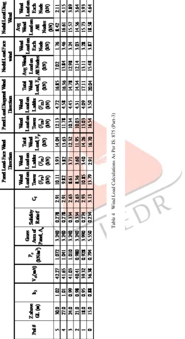
Wind load on tower and accessories Wind load Calculations: -
The wind load acting on Microwave tower is as per IS: 875(Part 3) -1987.As towers are tall and Flexible it is critical under wind load. The wind load is calculated by dividing the tower into different panels of equal heights. The calculated wind is transferred on each joint of the exposed face of the tower. Therefore: 875(Part 3) -1987 recommends the diagonal wind to be 1.2 times the wind blowing normal to the face. The design wind pressure is calculated at increasing height of tower from the mean ground level. The design wind speed is obtained taking into account factors such as risk co-efficient, terrain roughness, height, size of structure and local topography.
Height of Tower = 30 m Reference from IS: 875 (Part-3)
Structure Class = B 5.3.2.2
Basic wind speed Vb = 39 m/s Fig. 1
Terrain Category = 3 5.3.2.1
Risk Co-efficient k1 = 1.06 Table 1 Terrain, height and structure Size factor k2 = Varies Table 2
Topography Factor k3 = 1 5.3.3-Normal Topography
IJEDR1602374
International Journal of Engineering Development and Research (www.ijedr.org)2136
Table 5 Platform and Antenna load calculationsT
ab
le
4
W
in
d
L
o
ad
C
alcu
latio
n
s
As Per
I
S: 8
7
5
(
Par
IJEDR1602374
International Journal of Engineering Development and Research (www.ijedr.org)2137
Platform & Antenna Loads Wt (kg) Wind Load (kN) For Wind Speed (m/s) Ant Elv (m) Wind Speed (m/s) Wind Load/ Antenna (kN) # of Antennas Total Load (kN) Per Node (kN) RemarksPlatform 300 NA NA 30 42.27 NA NA 1.41 0.35 4 Nodes
GSM 2.5mx0.3m 25 1.26 44.44 30 42.27 1.14 4.00 4.57 1.14 4 Nodes
MW 1.8m dia 75 4.34 55.56 27 41.65 2.44 1.00 2.44 1.22 2 Nodes
MW 2.4m dia 200 7.72 55.56 24 41.03 4.21 1.00 4.21 2.11 2 Nodes
Table 6 Load combinations
LOAD COMBINATION LOAD FACTORS
SW DL WX (ANT) WX (TWR)
SW+DL+WX(ANT)+ WX(TWR)---FACE 1.0 1.0 1.5 1.5
SW+DL+WZ(ANT)+ WZ(TWR)---FACE 1.0 1.0 1.5 1.5
SW+DL+DIAG(ANT)+ DIAG(TWR)---DIAG 1.0 1.0 0.85 0.85
SW+DL+WX(ANT)+ WX(TWR)---FACE 1.0 1.0 -0.85 -0.85
FACE WIND X-DIRECTION 1.0 1.0 0.31 0.31
FACE WIND Z-DIRECTION 1.0 1.0 0.31 0.31
IV.RESULTSANDDISCUSSIONS
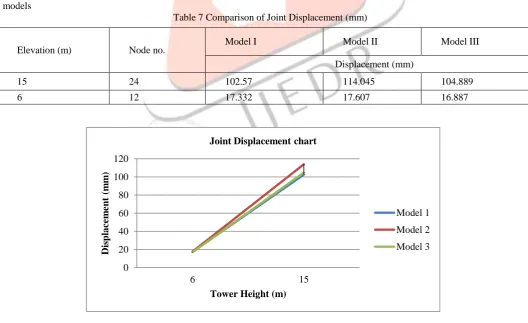
Displacement at the Top of Microwave Antenna Tower
In the present analysis, the displacement of microwave antenna tower at the top of 15m (i.e., 30 m of considering the building height) has been considered the main parameter.Fig.2 shows the variation displacement at the top of regular tower for different models
Table 7 Comparison of Joint Displacement (mm)
Fig2 Displacement at the Top of Microwave Antenna Tower 0 20 40 60 80 100 120 6 15 Dis pla ce m ent ( m m )
Tower Height (m) Joint Displacement chart
Model 1 Model 2 Model 3
Elevation (m) Node no. Model I Model II Model III
Displacement (mm)
15 24 102.57 114.045 104.889
IJEDR1602374
International Journal of Engineering Development and Research (www.ijedr.org)2138
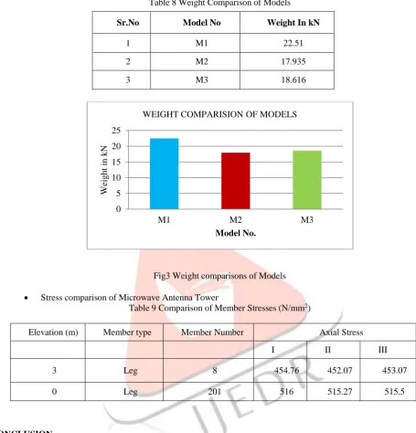
Weight comparison of Microwave Antenna TowerTable 8 Weight Comparison of Models
Fig3 Weight comparisons of Models Stress comparison of Microwave Antenna Tower
Table 9 Comparison of Member Stresses (N/mm2)
V.CONCLUSION
Cold formed steel has become a competitive building material as a result of industry wise efforts. To ensure sustained market growth for cold-formed steel in construction, AISI and steel market development institute will continue to play an important role to increase collaboration with different organizations to improve the design specification and to enhance the image and awareness of cold formed steel in the market place.
On the basis of present study, following conclusions can be drawn:
The wind analysis shows that irrespective of the model materials used for microwave tower does not significantly affect the displacement pattern, specifically the maximum lateral displacement at the top of tower.
The self weight for the M2 tower made of cold formed sections is found to be approximately 20 % less than other two towers hence a considerable amount of saving in material in case of cold form microwave tower is achieved
REFERENCES
[1] A.Jesumi, and M.G.Rajendran (2013): “Optimal Bracing system for steel Towers”, International Journal of Engineering Research and Applications, Volume 3, Issue 2, April 2013, ISSN: 2248-9622
[2] Amiri G. and Boostan A., (2002): “Dynamic Response of Antenna-Supporting Structures”, 4th Structural Specialty Conference of the Canadian Society for Civil Engineering, pp.1-9.
0 5 10 15 20 25
M1 M2 M3
W
eig
h
t
in
k
N
Model No.
WEIGHT COMPARISION OF MODELS Sr.No Model No Weight In kN
1 M1 22.51
2 M2 17.935
3 M3 18.616
Elevation (m) Member type Member Number Axial Stress
I II III
3 Leg 8 454.76 452.07 453.07
IJEDR1602374
International Journal of Engineering Development and Research (www.ijedr.org)2139
[3] G. Ghodrati Amiri and S. R. Massah (2007): “Seismic Response of 4-Legged Self-Supporting Telecommunication Towers”, International Journal of Engineering, Volume 20, No. 2, August 2007.[4] Nitin Bhosale, Prabhat Kumar and Pandey.A.D (2012): “Influence of Host Structure Characteristics on Response of Rooftop Telecommunication Towers”, International Journal of Civil and Structural Engineering Volume 2, No 3, February 2012, ISSN 0976 – 4399.
[5] Patil Vidya M. and Lande Abhijeet C. (2012): “Structural Response of Lattice Steel Masts for Seismic Loading”, IOSR Journal of Mechanical and Civil Engineering, September 2012, ISSN: 2278-1684.
[6] Richa Bhatt, A.D.Pandey and Vipul Prakash (2013): “Influence of Modeling in the Response of Steel Lattice Mobile Tower under Wind Loading”, International Journal of Scientific Engineering and Technology, Volume 2 Issue 3, April 2013, ISSN: 2277-1581.
[7] Siddesha.H (2010): “Wind Analysis of Microwave Antenna Towers”, International Journal of Applied Engineering Research, Dindigul, Volume 1, No 3, 2010, ISSN 0976-4259.Jithesh, Vijaya Page 79
[8] IS800:1984, Indian Standard Code of Practice for General Construction in Steel, Bureau of Indian Standards, New Delhi. [9] IS: 802 (part1/sec1): 1995, Indian Code of Practice for Use of Structural Steel in Overhead Transmission Line Towers, Part 1: Materials, Loads and Permissible Stresses. Bureau of Indian Standards, New Delhi.
[10] IS: 875 (part 3):1987, Indian Code of Practice for Design Loads (other than Earthquake) for Buildings and Structures, Part 3: Wind Loads. Bureau of Indian Standards, New Delhi.
[11] IS: 1893 (part 1): 2002, Indian Standard Criteria for Earthquake Resistant Design of Structures, Part 1: General Provisions and Buildings. Bureau of Indian Standards, New Delhi.
[12] IS: 801 – 1975, Indian standard code of practice for use of cold formed light gauge steel structural members in general building construction. Bureau of Indian Standards, New Delhi.
[13] IS: 811 – 1987 Indian standard specification for cold formed light gauge structural steel sections. Bureau of Indian Standards, New Delhi.
[14] BS 5950-51998 Structural use of steelwork in building-Part 5.Code of practice for design of cold formed thin guage sections.
[15] BS 8100-1:1986 Lattice towers and masts- Part 1: Code of practice for loading.