Satellite Image Enhancement Using Dwt-Swt Method
S.N.V.Vijaya Lakshmi & G.Vinod
M.Tech Department of ECE (DECS) GIER, Rajahmundry
Associate Professor Department of ECE GIER, Rajahmundry
ABSTRACT—In the area of image processing Satellite imaging is one of the testing assignments for the analysts. The diverse satellite
sensors are accessible in the low range to high range for information gathering. In our paper, a satellite image improvement calculation in light of addition of the high-recurrence sub bands acquired by discrete wavelet change (DWT) and the low determination input picture is proposed. This technique utilizes a DWT and high recurrence sub band picture addition into the low determination input pictures. The sharpness of picture is acquired by the estimation high recurrence sub band. Converse DWT is performed to recreate the resultant picture. The visual and numerical outcomes are exhibited and talked about on LANDSAT 8 information with correlation of proposed technique over ordinary and condition of craftsmanship determination improvement strategies. and also we have combined dwt with swt and improved the quality of the image
Keywords: Discrete wavelet transform,
interpolation, LANDSAT Imagery, Remote sensing, SWT.
I.
INTRODUCTION
The use of satellite pictures assembles well ordered due the change in the sensor advancements in atmosphere deciding, stargazing, arrive information et cetera. There is a need of have high assurance satellite pictures[1]. These photos are impacted by many components, for instance, maintenance scattering et cetera. Assurance of these photos is low in space. For development of assurance of satellite picture, in the written work numerous techniques are proposed. To secure high repeat picture unpretentious components an adaptable antagonistic to partner computation in perspective of the wavelet Fourier
as the widely appealing stage and IDWT as unequivocal stage which in all updates the idea of the photo.
II. INTERPOLATION
One of the normally utilized procedures for picture determination improvement is Interpolation. Interjection has been generally utilized as a part of many picture preparing applications, for example, facial recreation, various portrayal coding, and super determination. There are three understood interjection systems, specifically closest neighbor addition, bilinear introduction, and bi-cubic insertion. Addition is the way toward utilizing known information esteems to assess obscure information esteems. Different insertion methods are regularly utilized as a part of the environmental sciences[7].
A. Closest neighbor interjection
Closest neighbor interjection (otherwise called proximal insertion or, in a few settings, point inspecting) is a basic technique for multivariate addition in at least one dimensions. Interpolation is the issue of approximating the incentive for a non-given point in some space when non-given a few shades of focuses around (neighboring) that point. The closest neighbor calculation chooses the estimation of the closest point and does not think about the benefits of neighboring focuses by any means, yielding a piecewise-consistent interpolant. The calculation is extremely easy to actualize and is regularly utilized (more often than not alongside mapping) in genuine time3D rendering to choose shading esteems for a finished surface.
B. Bilinear interjection
In PC vision and picture preparing, bilinear insertion is one of the essential re inspecting techniques. In surface mapping, it is otherwise called bilinear separating or bilinear surface mapping, and it can be utilized to deliver a sensibly practical picture. A calculation is utilized to delineate screen pixel area to a comparing point on the surface guide. A weighted
connected to the screen pixel. This procedure is rehashed for every pixel shaping the protest being finished. At the point when a picture should be scaled up, every pixel of the first picture should be moved in a specific heading in light of the scale steady. Be that as it may, when scaling up a picture by a non-necessary scale factor, there are pixels (i.e., openings) that are not alloted proper pixel esteems. For this situation, those gaps ought to be appointed proper RGB or grayscale esteems so the yield picture does not have non-esteemed pixels.
III.EXISTING METHODS
can't state that at what time the specific occasion will has happened. In STFT, the window is settled. In this way, we this window won't change with the day and age of the flag i.e., for both limited determination and wide determination. Furthermore, we can't foresee the recurrence content at each time interim segment. To defeat the downsides of STFT, a wavelet method has been presented with variable window measure. Wavelet investigation permits the utilization of long time interims where we need more exact low-recurrence data, and shorter locales where we need high-recurrence data
So as to substitute the inadequacies forced by both the basic flag handling strategies, the wavelet strategy is utilized. The wavelet system is utilized to separate the highlights in a picture by preparing information at various scales. The wavelet method controls the scales to give a higher connection in recognizing the different recurrence parts in a picture. In fig.1 it is demonstrated that the examination of FT, STFT and wavelet change by considering a case input flag and how the investigation of change procedures will apply to get the recurrence data of info flag. We can watch that in wavelet examination the graphical portrayal demonstrates that the wavelet has more number of highlights than the FT and STFT. Wavelet is additionally called as multi determination investigation (MRA).
IV.WAVELET TRANSFORM
FOURIER ANALYSIS
Flag investigators as of now have available to them a noteworthy weapons store of devices. Maybe the most surely understood of these is Fourier examination, which separates a flag into constituent sinusoids of various frequencies. Another approach to consider Fourier investigation is as a numerical procedure for transforming our perspective of the flag from time-based to recurrence based.
For some signs, Fourier investigation is to a great degree valuable in light of the fact that the flag's recurrence content is of extraordinary significance. So for what reason do we require different procedures, similar to wavelet examination?
Fourier investigation has a genuine disadvantage. In changing to the recurrence space, time data is lost. When taking a gander at a Fourier change of a flag, it is difficult to tell when a specific occasion occurred. On the off chance that the flag properties don't change substantially after some time — that is, whether it is what is known as a stationary signal— this disadvantage isn't critical. Notwithstanding, most fascinating signs contain various non stationary or fleeting qualities: float, patterns, sudden changes, and beginnings and closures of occasions. These qualities are frequently the most critical piece of the flag, and Fourier investigation isn't suited to distinguishing them.
Taking a gander at a flag's wavelet decay tree can yield significant data.
A.NUMBER OF LEVELS
Since the examination procedure is iterative, in principle it can be proceeded with inconclusively. As a general rule, the deterioration can continue just until the point that the individual subtle elements comprise of a solitary specimen or pixel. By and by, you'll select a reasonable number of levels in view of the idea of the flag, or on an appropriate foundation, for example, entropy.
B. WAVELET RECONSTRUCTION:
We've figured out how the discrete wavelet change
examination. The other portion of the story is the manner by which those segments can be amassed once more into the first flag without loss of data. This procedure is called reproduction, or blend. The scientific control that impacts blend is known as the converse discrete wavelet transforms(IDWT). To incorporate a flag in the Wavelet Toolbox, we recreate it from the wavelet coefficients:
Where wavelet investigation includes separating and down inspecting, the wavelet recreation process comprises of up examining and sifting. Up inspecting is the way toward stretching a flag part by embeddings zeros between tests:
The Wavelet Toolbox incorporates summons like idwt and waverec that perform single-level or multilevel recreation separately on the parts of one-dimensional signs. These summons have their two-dimensional analogs, idwt2 and waverec2
C. RECREATION FILTERS:
down inspecting of the flag parts performed amid the decay stage presents a twisting called associating. For reasons unknown via painstakingly picking channels for the deterioration and reproduction stages that are firmly related (however not indistinguishable), we can "counteract" the impacts of associating.The low-and high pass deterioration channels (L low-and H), together with their related recreation channels (L' and H'), shape an arrangement of what is called Quadrature reflect channels:
D.REMAKING APPROXIMATIONS AND DETAILS:
We have seen that it is conceivable to remake our unique flag from the coefficients of the approximations and points of interest.
It is additionally conceivable to reproduce the approximations and points of interest themselves from their coefficient vectors.
For instance, how about we consider how we would recreate the primary level estimation A1 from the coefficient vector cA1. We pass the coefficient vector cA1 through a similar procedure we used to reproduce the first flag. Be that as it may, rather than joining it with the level-one detail cD1, we nourish in a vector of zeros set up of the detail coefficients
vector:
The procedure yields a remade approximationA1, which has an indistinguishable length from the first flag S and which is a genuine estimation of it. Essentially, we can reproduce the primary level detail D1, utilizing the practically equivalent to process:
The reproduced subtle elements and approximations are genuine constituents of the first flag. Actually, we find when we consolidate them that:
A1 + D1 = S
E.THE SCALING FUNCTION:
We've seen the interrelation of wavelets and Quadrature reflect channels. The wavelet work is dictated by the high pass channel, which additionally creates the points of interest of the wavelet disintegration. There is an extra capacity related with a few, however not all wavelets. This is the alleged scaling capacity. The scaling capacity is fundamentally the same as the wavelet work. It is dictated by the low pass Quadrature reflect channels, and along these lines is related with the approximations of the wavelet decay. Similarly that iteratively up-examining and convolving the high pass channel delivers a shape approximating the wavelet work, iteratively up-testing and convolving the low pass channel creates a shape approximating the scaling capacity.
F.MULTI-STEP DECOMPOSITION AND RECONSTRUCTION:
A multi step examination blend process can be spoken to as:
This procedure includes two angles: separating a flag to get the wavelet coefficients, and reassembling the flag from the coefficients. We've just examined deterioration and recreation at some length. Obviously, there is no point separating a flag only to have the fulfillment of quickly recreating it. We may alter the wavelet coefficients before playing out the remaking step. We perform wavelet examination in light of the fact that the coefficients along these lines acquired have many known uses, de-noising and pressure being first among them. Be that as it may, wavelet examination is as yet another and developing field. Almost certainly, numerous unknown employments of the wavelet coefficients lie in hold up. The Wavelet Toolbox can be a methods for investigating conceivable utilizations and heretofore obscure uses of wavelet examination. Investigate the tool kit capacities and see what you find.
G.WAVELET FAMILIES:
A few groups of wavelets that have turned out to be particularly valuable .some wavelet Families are
• Haar
• Daubachies • Biorthogonal • Coiflets • Symlets
• Morlet
• Mexicanhat
• Meyer
Essentially there are two stages associated with this picture upgrade operation. In the initial step, we do determination improvement. What's more, the second step is the complexity improvement. Determination upgrade utilizes the blend of DWT and SWT, and differentiation improvement utilizes the mix of SVD and DWT.
The square graph introduced underneath clarifies the significant advances engaged with the proposed system. At first we device a low determination picture with poor determination and poor enlightenment. The accompanying advances are completed to show signs of improvement rendition of the picture.
Thus, with a specific end goal to build the nature of the upgraded picture, safeguarding the edges is fundamental. In this paper, DWT has been utilized so as to save the high-recurrence segments of the image.DWT isolates the picture into various sub band
pictures, in particular, LL, LH, HL, and HH. A high-recurrence sub band contains the high high-recurrence part of the picture.
VI. IMAGE QUALITY ASSESSMENT
This segment manages the picture quality appraisal (IQA) measurements to quantify the nature of unflinching pictures. The IQA measurements utilizedas a part of this task are crest flag to commotion proportion (PSNR) and mean square mistake (MSE).Pinnacle motion to-clamor proportion, frequently contracted PSNR, is a designing term for the proportion between the most extreme conceivable energy of a flag and the energy of debasing noisethat influences the devotion of its portrayal. Since many signs have a wide powerful range, PSNR is generally communicated as far as the logarithmic decibel scale.PSNR is most usually used to gauge the nature of recreation of lossy pressure codecs (e.g., for picture pressure). The flag for this situation is the first information, and the commotion is the mistake presented by pressure. When looking at pressure codecs, PSNR is an estimate to human impression of remaking quality. In spite of the fact that a higher PSNR by and large demonstrates that the recreation is of higher quality, now and again it may not. One must be greatly watchful with the scope of legitimacy of this metric; it is just indisputably substantial when it is utilized to think about outcomes from the same codec (or codec sort) and same substance. PSNR is most effectively characterized by means of the mean squared blunder (MSE). Given a clamor free m×n monochrome picture I and its boisterous estimate K, MSE is characterized as
PSNR is characterized as takes after:
Where,
are spoken to utilizing 8 bits for every example, this is 255. All the more for the most part, when tests are spoken to utilizing direct PCM with B bits per test, MAXI is 2B−1. For shading pictures with three RGB esteems for each pixel, the meaning of PSNR is the same except the MSE is the sum over all squared value differences divided by image size and by three. Alternately, for color images the image is converted to a different color space and PSNR is reported against each channel of that color space, e.g., YCbCr or HSL.
VII.SIMULATION RESULTS
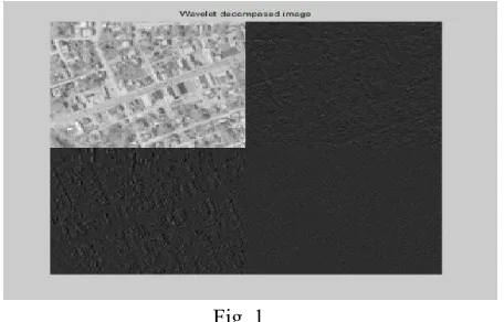
This segment deals with the experimental analysis that has been done in MATLAB environment. Fig4 shows that the original LR image, bilinear interpolated, bicubic interpolated and wavelet zero padded enhanced images. The output of decimated wavelet method and wavelet decomposed images has shown in fig5, in which the quality of the image has been increased over the conventional interpolation techniques. Fig6 shows that the proposed hybrid model, we can observe that the proposed approach has given better resolute image compared to the existing enhancement techniques. Quality metrics of various enhancement techniques has been shown in table1. It shows that the PSNR and MSE values of conventional interpolation, wavelet zero padding (WZP) and DWT-RE with existing method and in proposed method we combined DWT with SWT and improved the quality of image in Fig.7.
Fig.2
Fig.3
Fig.5
Fig.6
Fig.7
VIII.CONCLUSION
A review on various Ariel image enhancement techniques has been implemented, also compared the simulation results with the conventional interpolation and wavelet techniques. By observing the results we
can conclude that the proposed enhancement has given better performance than the existed methods. Furthermore, have extended the method DWT with combination of SWT and observed better image quality. and we calculated the PSNR values of various methods in dB for Bilinear 51.38 ,Bi-cubic 53.42 WZP 58.74 and in DWT method 59.299. Finally In DWT-SWT method we achieved a 65.8545dB PSNR in enhanced image.