Compact Dual-Band Bandpass Filter Based on Substrate Integrated
Waveguide Cavity with High Selectivity
Jing Li, Guanglin Li, Zhihua Wei, Guoqing Xu, Zongde Ju, and Jie Huang*
Abstract—A compact dual-band bandpass filter implemented with an embedded coplanar waveguide (ECPW) resonator and a capacitively loaded resonator (CLR) in substrate integrated waveguide (SIW) cavity is presented and analyzed in this paper. Three transmission zeroes (TZs), of which two are located in the middle of the two passbands and one located in the upper stopband, are obtained to improve the inner-band isolation and the selectivity of the filter. The center frequencies and bandwidths of the two passbands can be easily tuned by changing the geometrical parameters of the two resonators. The proposed dual-band SIW filter is demonstrated with center frequencies located at 8.41/14.29 GHz. The measured insertion loss is −1.28/−1.91 dB with the corresponding fractional bandwidth (FBW) of 21.2%/7.3%. The measured results are in good agreement with the simulated ones.
1. INTRODUCTION
Modern microwave and millimeter-wave filters are oriented towards compact size, sharp selectivity, high integration and easy manufacturability. To meet these requirements, substrate integrated waveguide (SIW) technology has been successfully applied to design filters due to its low loss and easy integration with other planar circuits [1–5]. Moreover, for the efficient utilization of spectrum resources, plenty of dual-band filters based on SIW technology have been proposed and designed [6–15]. In [6–8], several dual-mode SIW resonators are proposed to realize dual-band filters, but the sizes of these filters are relatively large. To achieve filters’ miniaturization, novel structures such as coupled complementary split-ring resonators (CSRR) [9], quadruple-folded SIW [10] and TM dielectric-loaded dual-mode cavities [11] are used to design compact dual-band SIW filters. However, these filters suffer from poor selectivity. Subsequently, many novel structures have been studied to design compact dual-band filters with high selectivity [12–15]. For instance, a dual-resonance SIW resonator structure which combines the miniaturization of the composite right/left-handed SIW with the high selectivity of the CSRR defected ground structure (DGS) is proposed to design a compact dual-band SIW filter [12]. Inverter coupled resonator sections are used in [13, 14] to introduce transmission zeroes into passbands, and dual-band SIW filters with high selectivity are obtained. In [15], a novel DGS structure with two-side loading scheme is proposed for miniaturized dual-band SIW filter designs with high selectivity. However, these proposed filters have relatively high insertion loss.
In this paper, a compact dual-band bandpass filter implemented with an embedded coplanar waveguide (ECPW) resonator and a capacitively loaded resonator (CLR) in SIW cavity is proposed. Three transmission zeroes (TZs) are generated to improve the selectivity and the isolation between the two passbands of the filter. The bandwidths and center frequencies of the two passbands can be adjusted flexibly by changing the geometrical parameters of the proposed resonators. In addition, the designed filter also features low insertion loss and broad bandwidth. Both the simulated analysis and measured results are demonstrated in details.
Received 4 May 2017, Accepted 14 October 2017, Scheduled 25 October 2017
* Corresponding author: Jie Huang ([email protected]).
2. ANALYSIS AND FILTER DESIGN
2.1. The Hybrid Structure of ECPW Resonator and SIW Cavity
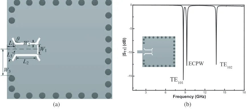
The configuration of the hybrid structure of the ECPW resonator and the SIW cavity is shown in Fig. 1(a). The ECPW acts as a quarter-wavelength resonator, and its resonant frequency is mainly determined by the geometrical parameters L2 and W3 [16]. The frequency response of the hybrid structure is simulated by Ansoft HFSS, and the corresponding result is shown in Fig. 1(b). It can be seen that the hybrid structure has three resonant frequencies in the frequency range of 0–18 GHz. The three resonant frequencies successively correspond to the TE101 mode of the SIW cavity, the resonant frequency of the ECPW resonator and the TE102 mode of the SIW cavity. The coupling effect between such an ECPW resonator and a SIW cavity has been analyzed detailedly in [16]. It has been demonstrated that not only magnetic coupling but also electric coupling exists between the ECPW resonator and the SIW cavity. As a result, a TZ located at finite frequency would be generated due to the mixed magnetic and electric coupling effect [17]. Using the conventional extracting method demonstrated in [18], the corresponding mixed coupling coefficient between the ECPW resonator and the SIW cavity can be extracted precisely, as shown in Fig. 2. It is worth noting that since the resonant frequencies of the ECPW resonator and the SIW cavity are different, one should use the coupling coefficient extracting formula for asynchronously tuned coupled resonators [18]. As can be observed from Fig. 2, the coupling coefficient can be effectively tuned by varying the geometrical parameter L3. It means that the required coupling coefficient can be obtained with proper geometrical parameters.
3 6 9 12 15 18 -15
-10 -5 0
TE102 ECPW
TE101
|S11
| (dB)
Frequency (GHz)
(a) (b)
Figure 1. (a) Configuration of the hybrid structure of the proposed ECPW resonator and the SIW cavity; (b) the corresponding frequency response of the hybrid structure.
2.2. ECPW-Based Filter Design
0.0 0.2 0.4 0.6 0.8 1.0 1.2 1.4 1.6 1.8 2.0 2.2 0.04
0.06 0.08 0.10 0.12 0.14 0.16 0.18 0.20 0.22
Coupling coefficients
L3
Figure 2. Coupling coefficient between the ECPW resonator and SIW cavity with differentL3.
(a) (b)
Figure 3. (a) Layout of the proposed ECPW-SIW filter; (b) the corresponding coupling scheme.
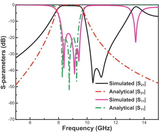
since the cross coupling between the two ECPW resonators is not considered, there would be no TZ in the ideal response. The corresponding mixed coupling coefficients are calculated ask12=k23= 0.1594, and then the key geometrical dimensions of the ECPW resonators can be determined according to the Fig. 2. The geometrical dimensions of the SIW cavity can be determined by its conventional resonant frequency formula [19]. The simulated response of the designed filter is shown in Fig. 4, in which two TZs located at the upper stopband can be observed as expected. The simulated response matches well with the ideal one, indicating that the desired filter response can be realized easily and accurately by using the design procedure above. The optimized geometrical dimension parameters are as follows:
W = 12.5 mm, L= 11.8 mm,L1= 0.8 mm,L2 = 3.2 mm,L3 = 1.12 mm,W1= 1.09 mm, W2 = 0.2 mm,
W3= 3.05 mm,θ= 105◦.
2.3. The Hybrid Structure of CLR and SIW Cavity
6 8 10 12 14 -70
-60 -50 -40 -30 -20 -10 0
S-parameters (dB)
Frequency (GHz)
Simulated |S21|
Analytical |S21|
Simulated |S11|
Analytical |S11|
Figure 4. Simulated and analytical response: |S21|&|S11|of the designed ECPW-SIW filter.
(a) (b)
Figure 5. (a) Configuration of the hybrid structure of the proposed CLR and the SIW cavity; (b) the corresponding equivalent transmission line model.
expressed as
B(ω) =ωC0−Y0cot
ω√εr
v h
(1)
3 6 9 12 15 18 -10
-8 -6 -4 -2
TEM
TE
102TE
101|S
11
| (
d
B)
Frequency (GHz)
Figure 6. Frequency response of the hybrid structure of the CLR and the SIW cavity.
(a) (b)
Figure 7. (a) Layout of the proposed CLR-SIW filter; (b) the coupling scheme of the CLR-SIW filter.
2.4. CLR-Based Filter Design
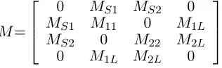
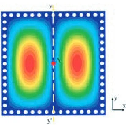
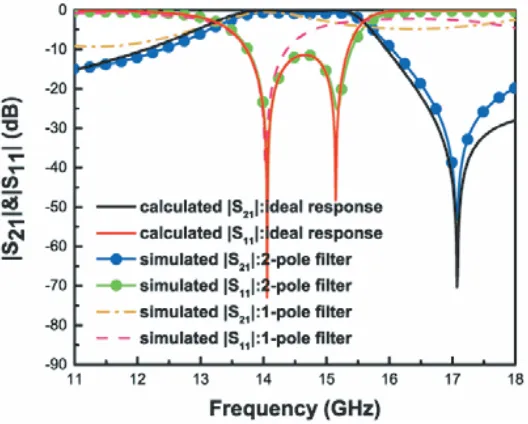
Figures 7(a) and (b) present the configuration of the proposed CLR-SIW filter and its corresponding coupling scheme. In such a configuration, the CLR would not be coupled to the TE102 mode of the SIW cavity, and this can be clarified through the electric field distributions of the TE102 mode. As shown in Fig. 8, the electric fields of the TE102 mode are mainly concentrated in two symmetrical areas with respect to they-axis, and the closer to the symmetrical axisyy, the smaller the magnitude of the electric field is. Consequently, when the CLR is placed at the center of the SIW cavity (shown as the red point A), it would not be coupled to the TE102 mode because the magnitude of the electric field of the TE102 mode reaches its minimum there. As shown in Fig. 7(b), the TE102 mode of the SIW cavity (f1) and the TEM mode of the CLR (f2) are individually coupled to the source/load, and thus two non-interacting electrical paths are generated. The two paths can produce two individual 1-pole filter responses to synthetize a desired 2-pole filter response. The corresponding coupling matrix M of the coupling scheme can be expressed as
M=
⎡ ⎢ ⎣
0 MS1 MS2 0
MS1 M11 0 M1L
MS2 0 M22 M2L
0 M1L M2L 0
⎤ ⎥
⎦ (2)
Figure 8. The electric field distribution of the TE102 mode of the SIW cavity.
negative coupling coefficient can be realized by using the transformation property of the TE102 mode of the SIW cavity [20], and thus a finite TZ would be generated. The location of the TZ can be determined as [21]
Ω=
M11MS22−M22MS21
M2
S1−MS22
(3)
It should be noted that Ω is the normalized frequency. The TZ can be placed at either the upper stopband or the lower stopband, depending on the sign of Ω.
Based on the analysis above, a 2-pole bandpass filter with center frequency of 14.5 GHz and FBW of 15% is designed. The TZ is placed at the normalized frequency Ω = 3. Using the synthesis methods proposed in [22], the corresponding coupling matrixM is calculated as
M=
⎡ ⎢ ⎣
0 0.7326 0.5215 0
0.7573 0.9724 0 −0.7573 0.5215 0 −1.1411 0.5215
0 −0.7573 0.5215 0
⎤ ⎥
⎦ (4)
Figure 9. Calculated response from the coupling matrix and simulated response of the structure shown in Fig. 7(a).
10 11 12 13 14 15 16 17 18
-50 -40 -30 -20 -10 0
|S
11
| &|
S21
| (d
B)
Frequency (GHz)
S
21S
11Figure 10. Simulated results: |S21|&|S11|of the demo filter with TZ located at the lower stopband.
s = 0.031 mm, r2 = 1.744 mm. It is demonstrated that the TZ can be placed at either the upper stopband or the lower stopband by properly adjusting the geometrical dimensions of the filter.
2.5. Dual-Band Bandpass Filter Design
3 6 9 12 15 18 -60 -50 -40 -30 -20 -10 0 |S 11 | &| S21 | (dB) Frequency (GHz) S21 S11 (a) (b)
Figure 11. (a) Configuration of the dual-band filter; (b) simulated results: |S21|& |S11|of the dual-band filter.
3 6 9 12 15 18
-50 -40 -30 -20 -10 0 |S 21 | (dB) Frequency (GHz)
d1=0.2mm d1=0.4mm d1=0.6mm d1=0.8mm
3 6 9 12 15 18
-70 -60 -50 -40 -30 -20 -10 0 |S 21 | (dB) Frequency (GHz)
L3=0.2mm L3=0.4mm L3=0.75mm L3=1.2mm
(a) (b)
Figure 12. Simulated results: |S21|of the filter with (a) differentL3; (b) differentd1.
The optimized geometrical parameters of the proposed filter are as follows: L1= 0.9 mm,L2 = 3.2 mm,
L3 = 0.75 mm, W1 = 1.5 mm, W2 = 0.2 mm, W3 = 4 mm, d1 = 0.4 mm,s= 0.015 mm, r2 = 0.705 mm,
d2 = 0.55 mm, s1= 0.6 mm. The corresponding simulated frequency response of the dual-band filter is shown in Fig. 11(b). The center frequencies of the two passbands are 8.44 GHz and 14.11 GHz, and the corresponding FBWs are 24.2% and 10.1%, respectively. Additionally, it also can be seen that the filter has three TZs, of which two TZs are located in the middle of two passbands and one is located in the right edge of the second passband. These TZs can effectively improve the inner-band isolation and the selectivity of the filter.
bandwidth of the second passband should be varied withd1. As shown in Fig. 12(a), whend1 increases, the bandwidth of the second passband also increases linearly. The first passband is designed by using the classical Chebyshev filter design method, and its bandwidth is mainly controlled by the coupling coefficients between the resonators [18]. It has been demonstrated in Section 2.1 that the coupling coefficient between the ECPW resonator and the SIW cavity can be tuned byL3, and thusL3 can be used to change the bandwidth of the first passband. As can be observed from Fig. 12(b), the bandwidth of the first passband decreases with the increase ofL3. Additionally, since the open stub of the ECPW resonator is close to the feedline, the coupling coefficient between the source/load and the CLR could also be changed by L3. Consequently, the performance of the second passband would also be varied withL3, as shown in Fig. 12(b).
As shown in Fig. 11(b), the filter suffers from poor out-of-band rejection in the upper stopband due to the higher mode of the SIW cavity. As an attempt to solve this problem, two stepped impedance open stubs lowpass filters (LPFs) are loaded at the input/output of the proposed filter, as shown in Fig. 13(a). The design of the LPFs is based on the analytical synthesis procedure [23] and the cut-off frequency of the LPF is set at 17 GHz. The geometrical parameters of the LPF are as follows: W4 = 1.09 mm,
W5 = 0.15 mm, W6 = 0.3 mm, L4 = 0.2 mm, L5 = 1 mm, L6 = 2.3 mm, L7 = 2.4 mm, L8 = 1.5 mm. As shown in Fig. 13(b), the out-of-band suppression of the filter drops below 30dB when the LPFs are loaded, indicating that the upper stopband characteristic of the filter is effectively improved with the LPFs.
3 6 9 12 15 18 -50
-40 -30 -20 -10 0
|S
21
|(dB)
Frequency (GHz) filter without LPFs
filter with LPFs > 30dB
(a) (b)
Figure 13. (a) Configuration of the final dual-band bandpass filter; (b) simulated results: |S21|of the filters with/without LPFs.
3. SIMULATED AND MEASURED RESULTS
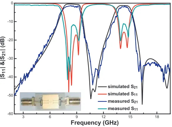
The proposed compact dual-band SIW filter with high selectivity is designed, fabricated and measured. A photograph of the final filter and its corresponding simulated and measured transmission responses are illustrated in Fig. 14. As observed, the measured results agree well with the simulated ones. In the simulated results, the center frequencies of the two passbands are located at 8.48 GHz and 14.29 GHz with FBWs of 24% and 11.3%, respectively. The corresponding insertion loss is−0.44/−1.26 dB. In the measured results, the two passbands are centered at 8.41 GHz and 14.29 GHz with FBWs of 21.2% and 7.3%. The measured insertion loss is −1.28/−1.91 dB, respectively. In addition, the upper stopband suppression is better than 30 dB in both simulated and measured results, suggesting a good out-of-band rejection of the proposed filter.
3 6 9 12 15 18 -60
-50 -40 -30 -20 -10 0
|S
11
| &|
S21
| (dB
)
Frequency (GHz)
simulated S21
simulated S11
measured S21
measured S11
Figure 14. Simulated and measured results: |S21|&|S11|of the final filter with the photograph of the fabricated filter.
Table 1. Comparison between the proposed filter and previous works.
Reference Size Insertion loss (dB) FBW
[12] 0.28λg∗0.27λg −2.42/−2.62 6.25%/5.2%
[24] design II 0.47λg∗0.47λg −1.16/−1.76 11.8%/5.4%
[24] design III 0.48λg∗0.48λg −1.8/−1.94 6.8%/3.2%
This work 0.33λg∗0.33λg −1.28/−1.91 21.2%/7.3%
Note: λg is the guide wavelength at the center frequency of the first passband.
size and exhibits good passband performances. Compared with other similar filters, the proposed one offers relatively broad bandwidth and low insertion loss.
4. CONCLUSION
In this paper, a compact dual-band bandpass SIW filter implemented with the ECPW resonator and the CLR is designed, fabricated and measured. The proposed dual-band SIW filter is centered at 8.41/14.29 GHz with FBWs of 21.2%/7.3% and the corresponding insertion loss −1.28/ −1.91 dB, respectively. Three TZs are introduced in the filter, and thus the high selectivity and good isolation performance are obtained. The measured results are in good agreement with the simulated ones. The designed compact dual-band SIW filter exhibits the characteristics of low insertion loss, good inner-band isolation, high selectivity and good out-of-band rejection, which shows the great potential for dual-band filter applications.
ACKNOWLEDGMENT
1. Deslandes, D. and K. Wu, “Single-substrate integration technique of planar circuits and waveguide filters,”IEEE Trans. Microwave Theory Tech., Vol. 51, 593–596, Feb. 2003.
2. Chen, R. S., S. W. Wong, L. Zhu, and Q. X. Chu, “Wideband bandpass filter using U-slotted substrate integrated waveguide (SIW) cavities,” IEEE Microwave and Wireless Components Letters, Vol. 25, No. 1, Jan. 2015.
3. Wei, Z. H., J. Huang, Y. H. Geng, J. Li, and G. Q. Xu, “Compact broadband bandpass filter on quarter-mode substrate integrated waveguide loaded with CRLH interdigital slots,” Progress In Electromagnetics Research Letters, Vol. 59, 85–91, 2016.
4. Li, X., Z. H. Shao, and C. J. You, “X-band substrate integrated waveguide bandpass filter using novel defected ground structure cell,” Microwave and Optical Technology Letters, Vol. 57, No. 5, May 2015.
5. Dong, K. D., J. Y. Mo, Y. H. He, Z. W. Ma, and X. X. Yang, “Design of a millimeter-wave dual-band dual-bandpass filter using SIW dual-mode cavities,” 2016 IEEE MTT-S International Wireless Symposium (IWS), 14–16, Mar. 2016.
6. Wu, Y. L., Y. Q. Chen, L. X. Jiao, Y. A. Liu, and Z. Chassemlooy, “Dual-band dual-mode substrate integrated waveguide filters with independently reconfigurable TE101 resonant mode,” Scientific Reports, Vol. 6, 31922, 2016.
7. Xu, X., J. P. Wang, G. Zhang, and J. X. Chen, “Design of balanced dual-band bandpass filter based on substrate integrated waveguide,”Electronics Letters, Vol. 49, No. 20, 1278–1280, Sept. 26, 2013. 8. Rezaee, M. and A. R. Attari, “A novel dual mode dual band SIW filter,” 2014 44th Microwave
Conference (EuMC), European, Oct. 6–9, 2014.
9. Wei, F., P. Y. Qin, Y. J. Guo, C. Ding, and X. W. Shi, “Compact balanced dual- and tri-band BPFs based on coupled complementary split-ring resonators (C-CRSS),”IEEE Microwave and Wireless Components Letters, Vol. 26, No. 2, Feb. 2016.
10. Shen, W., W. Y. Yin, and X. W. Sun, “Miniaturized dual-band substrate integrated waveguide filter with controllable bandwidths,”IEEE Microwave and Wireless Components Letters, Vol. 21, No. 8, Aug. 2011.
11. Nocella, V., L. Pelliccia, C. Tomassoni, and R. Sorrentino, “Miniaturized dual-band waveguide filters using TM dielectric-loaded dual-mode cavities,” IEEE Microwave and Wireless Components Letters, Vol. 26, No. 5, May 2016.
12. Zhao, Q., Z. L. Chen, J. Huang, G. L. Li, Z. H. Zhang, and W. Dang, “Compact dual-band bandpass filter based on composite right/left-handed substrate integrated waveguide loaded by complementary split-ring resonators defected ground structure,”Journal of Electromagnetic Waves and Applications, Vol. 28, No. 14, 1807–1814, 2014.
13. Shen, Y. J., H. Wang, W. Kang, and W. Wu, “Dual-band SIW differential bandpass filter with improved common-mode suppression,”IEEE Microwave and Wireless Components Letters, Vol. 25, No. 2, Feb. 2015.
14. Chen, X. P., K. Wu, and Z. L. Li, “Dual-band and triple-band substrate integrated waveguide filters with chebyshev and quasi-elliptic responses,”IEEE Trans. Microwave Theory Tech., Vol. 55, No. 12, Dec. 2007.
15. Xu, S. S., K. X. Ma, F. Y. Meng, and K. S. Yeo, “Novel defected ground structure and two-side loading scheme for miniaturized dual-band SIW bandpass filter designs,” IEEE Microwave and Wireless Components Letters, Vol. 25, No. 4, Apr. 2015.
16. Chu, P., W. Hong, L. L. Dai, H. J. Tang, J. X. Chen, Z. C. Hao, X. C. Zhu, and K. Wu, “A planar bandpass filter implemented with a hybrid structure of substrate integrated waveguide and coplanar waveguide,” IEEE Trans. Microwave Theory Tech., Vol. 62, No. 2, Feb. 2014.
18. Hong, J. S. and M. J. Lancaster, Microstrip Filters for RF/Microwave Application, 1st Edition, Wiley, New York, NY, USA, 2001.
19. Chen, X. P., W. Hong, T. J. Cui, J. X. Chen, and K. Wu, “Substrate integrated waveguide (SIW) linear phase filter,”IEEE Microwave and Wireless Components Letters, Vol. 15, No. 11, 787–789, 2005.
20. Rosenberg, U., “New “planar” waveguide cavity elliptic function filters,” European Microwave Conference, Vol. 1, 524–527, 1995.
21. Liao, C. K., P. L. Chi, and C. Y. Chang, “Microstrip realization of generalized Chebyshev filters with box-like coupling schemes,” IEEE Trans. Microwave Theory Tech., Vol. 55, No. 1, 147–153, 2007.
22. Cameron, R. J., “Advanced coupling matrix synthesis techniques for microwave filter,”IEEE Trans. Microwave Theory Tech., Vol. 51, No. 1, 1–10, 2003.
23. Matthaei, G. L., L. Young, and E. M. T. Jones,Microwave Filters, Impedance Matching Networks, and Coupling Structures, McGraw-Hill, New York, NY, USA, 1964.