Scholarship@Western
Scholarship@Western
Electronic Thesis and Dissertation Repository
August 2016
Complex Event Processing as a Service in Multi-Cloud
Complex Event Processing as a Service in Multi-Cloud
Environments
Environments
Wilson A. Higashino
The University of Western Ontario
Supervisor
Dr. Miriam A. M. Capretz
The University of Western Ontario
Graduate Program in Electrical and Computer Engineering
A thesis submitted in partial fulfillment of the requirements for the degree in Doctor of Philosophy
© Wilson A. Higashino 2016
Follow this and additional works at: https://ir.lib.uwo.ca/etd
Part of the Databases and Information Systems Commons
Recommended Citation Recommended Citation
Higashino, Wilson A., "Complex Event Processing as a Service in Multi-Cloud Environments" (2016). Electronic Thesis and Dissertation Repository. 4016.
https://ir.lib.uwo.ca/etd/4016
This Dissertation/Thesis is brought to you for free and open access by Scholarship@Western. It has been accepted for inclusion in Electronic Thesis and Dissertation Repository by an authorized administrator of
The rise of mobile technologies and the Internet of Things, combined with advances in Web technologies, have created a new Big Data world in which the volume and velocity of data gen-eration have achieved an unprecedented scale. As a technology created to process continuous streams of data, Complex Event Processing (CEP) has been often related to Big Data and used as a tool to obtain real-time insights. However, despite this recent surge of interest, the CEP market is still dominated by solutions that are costly and inflexible or too low-level and hard to operate.
To address these problems, this research proposes the creation of a CEP system that can be o↵ered as a service and used over the Internet. Such a CEP as a Service (CEPaaS) system
would give its users CEP functionalities associated with the advantages of the services model, such as no up-front investment and low maintenance cost. Nevertheless, creating such a service involves challenges that are not addressed by current CEP systems. This research proposes solutions for three open problems that exist in this context.
First, to address the problem of understanding and reusing existing CEP management pro-cedures, this research introduces the Attributed Graph Rewriting for Complex Event Process-ing Management (AGeCEP) formalism as a technology- and language-agnostic representa-tion of queries and their reconfigurarepresenta-tions. Second, to address the problem of evaluating CEP query management and processing strategies, this research introduces CEPSim, a simulator of cloud-based CEP systems. Finally, this research also introduces a CEPaaS system based on a multi-cloud architecture, container management systems, and an AGeCEP-based multi-tenant design.
To demonstrate its feasibility, AGeCEP was used to design an autonomic manager and a selected set of self-management policies. Moreover, CEPSim was thoroughly evaluated by experiments that showed it can simulate existing systems with accuracy and low execution overhead. Finally, additional experiments validated the CEPaaS system and demonstrated it achieves the goal of o↵ering CEP functionalities as a scalable and fault-tolerant service. In
tandem, these results confirm this research significantly advances the CEP state of the art and provides novel tools and methodologies that can be applied to CEP research.
Keywords: Complex Event Processing, Cloud Computing, Multi-Cloud, Container
Man-agement System, Simulation, Graph Rewriting
The work presented in Chapters 4 and 5 (Attributed Graph Rewriting for CEP Management) has been developed in collaboration with Dr. C´edric Eichler from INSA Centre Val de Loire/
LIFO Laboratory. Dr. Eichler’s main contribution was the introduction of graph rewriting rules as a formalism to express reconfiguration actions of Complex Event Processing queries. In addition, Dr. Eichler contributed with discussions about the scope and goals of the presented formalism, as well as with his expertise about autonomic computing.
First and foremost, I would like to thank my supervisor Dr. Miriam Capretz for her supervision, mentoring, and for welcoming me in a new country and making me feel like home. I will always be grateful for the many opportunities you gave me and for the countless hours you spent making me a better person and professional.
I would also like to thank my co-supervisor Dr. Luiz Fernando Bittencourt for having me half way in the program, and for his support and orientation through these years. You are a great source of inspiration.
To my parents, who have always believed and encouraged me through my journey.
To my beloved Ana, who has always supported me and has never left my side even in the most difficult moments.
To my brother and my nephew, who inspires me and makes me laugh every Sunday.
To Dr. Beatriz Puzzi and Mr. Carlos Taube for your assistance and encouragement.
To Dr. Cédric Eichler, Dr. Thierry Monteil, and Dr. Ernesto Exposito for the incredible collaboration in this thesis.
To Powersmiths International Corp. for the great project in which I had the opportunity to work, and for providing the data used in many experiments from this thesis.
To all my colleagues from TEB 346. During all these years, you came from all around the world and without you this would not have been possible.
To all of you who should be thanked, but are not in this symbolic list. You all know who you are.
Contents
Abstract ii
Co-Authorship Statement iii
Acknowledgements iv
List of Figures x
List of Tables xiii
List of Appendices xiv
List of Acronyms xv
1 Introduction 1
1.1 Motivation . . . 2
1.2 Contributions . . . 4
1.3 Thesis Organization . . . 5
2 Background 8 2.1 Event Processing . . . 8
2.1.1 Stream Processing . . . 9
2.1.2 Complex Event Processing . . . 10
2.1.3 Concepts and Terminology . . . 11
2.1.4 Classification of CEP systems . . . 12
2.1.5 Query Lifecycle . . . 14
2.2 Cloud Computing . . . 17
2.2.1 Cloud Computing Definition . . . 17
2.2.2 Cloud Computing Architecture . . . 18
2.2.3 Multiple Cloud Architectures . . . 20
2.3 Container-Based Virtualization . . . 22
2.4 Autonomic Computing . . . 27
2.5 Summary . . . 28
3 Literature Review 30 3.1 Complex Event Processing . . . 30
3.1.1 Traditional Systems . . . 30
3.1.2 Modern Systems . . . 32
3.1.3 CEP Services . . . 40
3.1.4 Multi-Cloud CEP . . . 41
3.1.5 Comparison . . . 42
3.1.6 Discussion . . . 44
3.2 CEP Formal Models . . . 45
3.3 Cloud Computing Simulators . . . 46
3.4 Summary . . . 48
4 Attributed Graph Rewriting for CEP Management - Concepts 49 4.1 Motivation . . . 49
4.2 Attributed Graph Rewriting for CEP Management . . . 51
4.2.1 Modelling Queries . . . 51
4.2.2 Modelling Reconfiguration Actions . . . 52
4.2.3 Discussion . . . 52
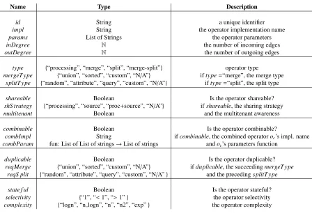
4.3 Classification of CEP Operators . . . 53
4.3.1 Operator Type . . . 54
4.3.2 Sharing . . . 55
4.3.3 Duplication . . . 57
4.3.4 Combination . . . 58
4.3.5 Behaviour . . . 59
4.3.6 Discussion . . . 59
4.4 Representation of Queries and Reconfigurations . . . 59
4.4.1 Query Representation Using ADAGs . . . 60
4.4.2 Query Reconfiguration Using Graph Rewriting . . . 66
4.5 Summary . . . 70
5 Attributed Graph Rewriting for CEP Management - Evaluation 72 5.1 AGeCEP-Based Autonomic Manager . . . 72
5.1.2 MAPE Modules . . . 73
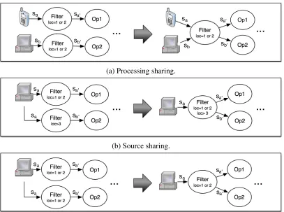
5.2 Feasibility: Operator Placement . . . 76
5.2.1 General Principle . . . 76
5.2.2 Examples . . . 77
5.3 Feasibility: Self-Management Policies . . . 78
5.3.1 Operator Combination . . . 78
5.3.2 Operator Duplication . . . 79
5.3.3 Removal of an Unnecessary Merge/Split . . . 81
5.3.4 Processing Sub-Streams (ProcSubS) . . . 84
5.3.5 Predicate Indexing . . . 88
5.4 Viability: Performance Evaluation . . . 89
5.4.1 Simple Policy . . . 89
5.4.2 Complex Policy . . . 89
5.5 Summary . . . 91
6 Complex Event Processing Simulator 93 6.1 Motivation . . . 93
6.2 System Overview . . . 94
6.3 CEPSim Foundation . . . 96
6.3.1 Query Model . . . 96
6.3.2 Event Sets . . . 98
6.3.3 Event Set Queues . . . 100
6.4 CEPSim Simulation . . . 101
6.4.1 Operator Placement . . . 101
6.4.2 Operator Scheduling . . . 101
6.4.3 Operator Simulation . . . 102
6.4.4 Placement Simulation . . . 106
6.4.5 Metrics . . . 110
6.5 Evaluation . . . 112
6.5.1 Case Study . . . 112
6.5.2 Environment . . . 113
6.5.3 Set-Up . . . 113
6.5.4 Validation . . . 115
6.5.5 CPU and Memory Overhead . . . 119
6.5.6 Simulation Parameters . . . 121
7 Complex Event Processing as a Service 125
7.1 Motivation . . . 125
7.2 System Overview . . . 126
7.3 System Architecture . . . 128
7.3.1 Container Management System . . . 128
7.3.2 Message Broker . . . 130
7.3.3 CEPaaS Core/Web/Data Storage . . . 131
7.3.4 Config Manager . . . 132
7.3.5 Query Analyzer and Manager . . . 132
7.4 System Design . . . 133
7.4.1 Tenant . . . 133
7.4.2 Vertex Templates . . . 134
7.4.3 Queries . . . 135
7.5 System Implementation . . . 136
7.5.1 Events . . . 136
7.5.2 Vertex Template Logic . . . 137
7.5.3 Built-In Templates . . . 140
7.5.4 Query Execution Engine . . . 142
7.5.5 Limitations . . . 147
7.6 Evaluation . . . 148
7.6.1 Set-Up . . . 148
7.6.2 Latency Evaluation . . . 150
7.6.3 Fault Tolerance . . . 151
7.7 Summary . . . 153
8 Conclusion 154 8.1 Contributions . . . 155
8.2 Future Work . . . 157
Bibliography 160 A Self-Management Policies Inference Rules 178 B CEPSim Implementation 181 B.1 Overview . . . 181
B.3 CEPSim Integration . . . 184
C CEP as a Service API 186
D CEP as a Service Operator Template Definition 188
Curriculum Vitae 190
2.1 CEP terminology. . . 12
2.2 An SQuAl query example (adapted from Abadiet al. [1]). . . 14
2.3 Query lifecycle. . . 14
2.4 Cloud computing architecture (adapted from Zhanget al. [154]). . . 18
2.5 Simplified cloud computing architecture (adapted from Armbrustet al. [21]). . 19
2.6 Multiple cloud models. . . 21
2.7 Alternative multiple cloud models. . . 22
2.8 Hypervisor architectures. . . 23
2.9 Container-based virtualization. . . 23
2.10 Kubernetes architecture (adapted from Google [63]). . . 27
2.11 MAPE-K autonomic loop. . . 29
4.1 AGeCEPclassification of operators. . . 53
4.2 Operator types - examples. . . 54
4.3 Sharing strategies. . . 56
4.4 Duplication strategy. . . 57
4.5 Combination strategy. . . 58
4.6 JSON to XML conversion - Storm queries. . . 62
4.7 Additional examples of edge attributes. . . 63
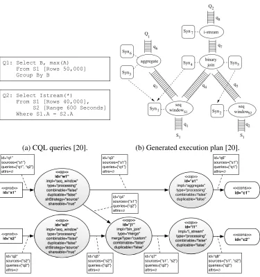
4.8 Conversion from a CQL query toAGeCEP. . . 64
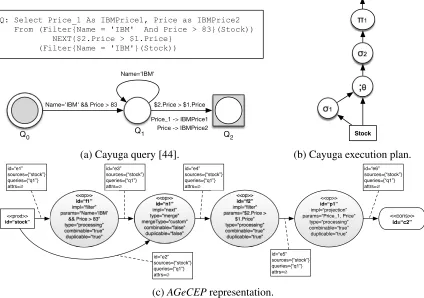
4.9 Conversion from a Cayuga query toAGeCEP. . . 65
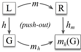
4.10 Construction of a push-out: application of a graph rewriting rule. . . 67
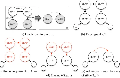
4.11 Illustration of a graph rewriting rulerand its application. . . 68
4.12 Combination of two combinable successive operatorsPcomb. . . 70
4.13 Queryq1- optimized version. . . 70
5.1 Runtime environment representation. . . 73
5.2 Pinit dupl(id): initial duplication. . . 82
5.3 Padd dupl(id,so): additional duplication. . . 83
5.4 Prem(idm,ids): removal of an unnecessary merge/split. . . 85
5.6 Ppred: predicate indexing. . . 88
5.7 Combpolicy execution time. . . 90
5.8 Queryq2- optimized version. . . 90
5.9 DuplandRemMS policies execution times. . . 91
6.1 CEPSimoverview. . . 95
6.2 CEPSimquery example. . . 96
6.3 Windowed operator attributes. . . 97
6.4 Placement definitions. . . 101
6.5 Windowed operator simulation. . . 105
6.6 Execution of a simulation tick. . . 107
6.7 Networked query simulation. . . 109
6.8 Event sets created during a simulation tick. . . 111
6.9 Throughput calculation - duplicatedtotalscount. . . 111
6.10 Storm topologies. . . 112
6.11 Storm queries converted to theAGeCEPmodel. . . 114
6.12 Metrics estimation results - queryq1. . . 116
6.13 Metrics estimation results - queryq2. . . 117
6.14 Metrics estimation results - networked queryq1. . . 118
6.15 Execution time and memory consumption - single VM. . . 120
6.16 Execution time and memory consumption - multiple VMs. . . 120
6.17 Parameters experiments - Scheduling and allocation strategies. . . 121
7.1 CEPaaSsystem architecture. . . 127
7.2 Apache Kafka architecture. . . 131
7.3 Class diagram of theCEPaaSsystem. . . 134
7.4 CEPaaScore concepts. . . 136
7.5 Events - JSON representation. . . 137
7.6 Vertex template definition. . . 138
7.7 Vertex template definition interfaces. . . 138
7.8 Query state machine diagram. . . 139
7.9 A DRL rule definition. . . 140
7.10 Kafka Producer and Consumer. . . 141
7.11 Sequence diagram - query creation. . . 143
7.12 Sequence diagram - query start - part 1. . . 144
7.13 Sequence diagram - query start - part 2. . . 145
7.16 Query latency - 95% percentile - client inus-east-1region. . . 150
7.17 Query latency - 95% percentile - client inasia-northeast-2region. . . 151
7.18 Query latency - fault tolerance experiment. . . 152
7.19 Query latency - fault tolerance experiment in a complex scenario. . . 152
B.1 CEPSimcomponents. . . 182
B.2 Class diagram -eventandquery modelpackages. . . 182
B.3 Class diagram -query executorandmetricspackages. . . 183
B.4 CEPSimintegration with CloudSim. . . 184
B.5 Sequence diagram - simulation cycle. . . 185
D.1 Filter operator metadata. . . 188
D.2 Filter operator implementation. . . 189
List of Tables
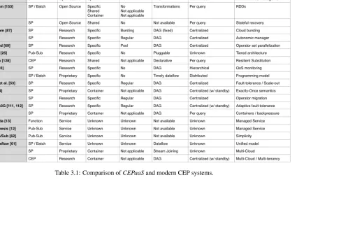
3.1 Comparison ofCEPaaSand modern CEP systems. . . 43
4.1 Attributes of the vertex stereotype “operator”. . . 61
4.2 Edge attributes. . . 61
5.1 Monitored events. . . 74
6.1 Storm VM cluster specification. . . 113
6.2 Software specification. . . 114
6.3 Simulation parameters. . . 115
6.4 Multiple queries experiment - Latency measurements (in ms). . . 119
6.5 Parameters experiments - Simulation tick length. . . 122
C.1 CEPaaS CoreAPI. . . 187
Appendix A Self-Management Policies Inference Rules . . . 178
Appendix B CEPSim Implementation . . . 181
Appendix C CEP as a Service API . . . 186
Appendix D CEP as a Service Operator Template Definition . . . 188
ADAG Attributed Directed Acyclic Graph
AGeCEP Attributed Graph Rewriting for Complex Event Processing Management
API Application Program Interface
CEP Complex Event Processing
CEPaaS Complex Event Processing as a Service
CMS Container Management System
CQL Continuous Query Language
CRUD Create Read Update Delete
DAG Directed Acyclic Graph
DBMS Database Management System
EPN Event Processing Network
IaaS Infrastructure as a Service
KB Knowledge Base
KCL Amazon Kinesis Client Library
MAPE-K Monitor Analyze Plan Execute - Knowledge
MQO Multi-Query Optimization
PaaS Platform as a Service
QAM Query Analyzer and Manager
QLM Query Lifecycle Management
QoS Quality of Service
REST Representational State Transfer
SaaS Software as a Service
SP Stream Processing
SQL Structured Query Language
SQO Single-Query Optimization
VM Virtual Machine
Introduction
The emergence of Big Data has been profoundly changing the way enterprises and organiza-tions store and process data. Clearly, the sheer amount of data created by mobile devices, the Internet of Things (IoT), and a myriad of other sources cannot be handled by traditional data processing approaches [64]. Simultaneously, there is also a consensus that obtaining insights and generating knowledge from these Big Data can bring a competitive advantage to organi-zations using them. Therefore, these organiorgani-zations, along with the research community, have been actively pursuing new ways of leveraging Big Data to improve their businesses.
According to the most commonly accepted definition, Big Data is characterized by four Vs [121]: volume, velocity, variety, and veracity. Volume refers to the quantity of data, and velocity concerns the speed at which data are generated and need to be processed. Variety refers to the diversity of data types and formats, and veracity relates to the accuracy and reliability of the data [65]. Datasets can be “big” in any of these directions and, most often, in more than one. For instance, volume and velocity are closely related, as fast data generation usually results in a massive amount of data to be stored and processed.
As technologies created to process continuous streams of data with low latency, Complex Event Processing (CEP) and Stream Processing (SP) have often been related to the velocity dimension and used in the Big Data context. The processing model of CEP and SP systems are both based on continuously running user-defined queries that dictate operations to be per-formed on fast and often distributed input streams. The goal is usually to obtain real-time insights and to enable prompt reaction to them. Because of the generality of this model, these systems have been applied to a variety of use cases ranging from simple monitoring to highly complex financial applications such as fraud detection and automated trading [65].
At about the same time, cloud computing has also emerged as a disruptive computational paradigm for on-demand network access to a shared pool of computing resources such as servers, storage, and applications [113]. From the infrastructure point of view, cloud
ing environments are leveraged to provide the low-latency and scalability needed by modern applications, including CEP and SP systems [69, 128]. From the business perspective, cloud computing provides an agile way to access infrastructure resources and services without large upfront investments and preparation time.
Despite the paradigm shift brought about by cloud computing, today the CEP and SP mar-ket is still dominated by a few proprietary solutions [86, 123, 139] that require huge investments for acquisition and do not provide the flexibility that users need. Alternatively, on the other side of the spectrum many companies adopt open-source, low-level systems [17, 18, 153], which demand intense technical training and have high operating costs.
To address these problems, this research proposes the creation of a CEP system that can be o↵ered in theSoftware as a Service (SaaS) model. ThisCEP as a Service(CEPaaS)
sys-tem would enable users to access CEP functionalities on-demand, over the Internet, and with minimal management e↵ort. However, o↵ering such a service involves many challenges that
are not addressed by current CEP state of the art. This thesis discusses these challenges further and presents a series of contributions towards the development of such a system.
1.1 Motivation
The use of CEP and SP solutions to analyze streaming data and obtain real-time insights has the potential to profoundly change enterprises and make them more agile and responsive. This impact has been confirmed by a recent survey, which estimated a market of $500 million in 2015 for the so-called streaming analytics solutions, with the potential to reach $2 billion in 20201. Nevertheless, despite this growing interest, this market is still dominated by a few
solutions that are costly and inflexible or too low-level and hard to operate.
The o↵ering ofSoftware as a Service (SaaS) is a recent paradigm shift that has been at the
core of thecloud computing revolution. In the SaaS model, software traditionally only avail-able as proprietary packages are now o↵ered as services that can be consumed on-demand and
with minimal management e↵ort. Likewise, even the computational infrastructure normally
required by enterprise systems can now be consumed as always-available services. This of-fering of Infrastructure as a Service (IaaS), in conjunction with SaaS, brings many benefits to enterprises, including reducing their capital investments, mitigating risks, and focusing on innovation and di↵erentiation.
Given this scenario, it is only natural to imagine the o↵ering ofCEPaaSas a way to bring
to CEP users the many advantages of the services model, such as:
• No up-front investment in hardware and software infrastructure.
• Low maintenance cost, as the service model reduces the need for infrastructure monitor-ing and maintenance.
• Constant upgrades, mostly without interruption and at no charge.
• Ubiquitous access using the Internet.
Nevertheless, such CEP services either do not exist today or are very limited in their nature, which can be tracked to the many challenges involved in developing them and the lack of appropriate solutions in the current state of the art.
The first of these challenges is related tounderstandingcurrent systems andreusingresults that already exist in the form of algorithms and management procedures. The current CEP re-search landscape is still young and fragmented. A large variety of solutions exist, but they often use inconsistent terminology and di↵erent query definition languages. Consequently, most
on-going research is performed in the context of specific systems and languages. In particular, algorithms and procedures aimed at managing the user queries have often been developed in such a system-specific fashion that they cannot be easily generalized and applied to other con-texts.
The second challenge is related to evaluating and comparing CEP query processing and management approaches. Today, this problem acquires even more challenging characteristics because most modern CEP systems use cloud environments as their runtime platform. In this type of environment, validating management procedures in the required Big Data scale is a research problemper se. For example, cloud environments are subject to variations that make it difficult to reproduce the environment and conditions of an experiment [56]. Moreover,
setting up and maintaining large cloud environments are laborious and error-prone, and may be associated with a high financial cost. Finally, there are also many challenges related to generating and storing the volume of data required by Big Data experiments.
Finally, many technical difficulties are associated with the design and implementationof
a CEPaaS system. For instance, low latency is essential to many CEP use cases, but it is
difficult to achieve in a service environment because there is no control over the locations of
event sources and consumers. Such aCEPaaS system is also inherently multi-tenancy, which makes fault-tolerance essential because an outage can a↵ect many customers and damage the
provider’s reputation. In addition, multi-tenancy indicates that some sort of resource control and isolation is necessary to avoid interference between workloads from di↵erent queries.
Fi-nally, by o↵ering it to anyone with Internet access, the system is expected to be highly scalable
1.2 Contributions
This research provides aseriesof contributions aimed to solve the challenges mentioned and, ultimately, to enable the development of aCEPaaSsystem.
To solve the challenge ofunderstanding current systems andreusing existing results, this research introduces the Attributed Graph Rewriting for ComplexEventProcessing Manage-ment (AGeCEP), a formalism that provides technology- and language-agnostic representations of queries and of reconfiguration actions that can be applied to transform these queries.
In AGeCEP, queries are modelled as attributed graphs and described by a standard set of
attributes, whereas reconfiguration actions are expressed by graph rewriting rules. In con-junction, these models provide a common foundation that can be used to represent queries written in di↵erent languages and to express generic CEP management procedures. By
do-ing so, these procedures can be integrated into any modern cloud-based CEP system that uses
AGeCEPas its underlying formalism. In particular,AGeCEPis especially suitable to represent
self-management policies that can be used to manage and control autonomic CEP systems. This research harnesses AGeCEP expressiveness by adopting it as the formal foundation of the other contributions. To demonstrate its feasibility, AGeCEP is also used to design an autonomic manager and to define a selected set of self-management policies. In addition,
AGeCEPviability is verified through performance measurement experiments, which show that
100 queries can be processed and rewritten by graph rewriting rules in less than one second. The second major contribution of this research isCEPSim, a simulator for cloud-based CEP systems. Traditionally, simulators have been used in di↵erent fields to overcome difficulties
related to the execution of repeatable and reproducible experiments [33, 34, 92, 119].CEPSim
aims to bring simulation capabilities to CEP and to solve the challenges of evaluating and
comparingdi↵erent query processing and management strategies.
CEPSimuses a query model based onAGeCEPand introduces simulation algorithms based
on a novel abstraction calledevent sets. CEPSimcan model di↵erent types of clouds, including
public, private, hybrid, and multi-cloud environments, and simulate execution of user-defined queries on them. Moreover, it can also be customized with various operator placement and scheduling strategies. These features enable architects and researchers to analyze the scalability and performance of cloud-based CEP systems and to easily compare the e↵ects of adopting
di↵erent query processing strategies.
A large set of experiments was executed to analyze CEPSim. Results show that CEPSim
The last major contribution of this research is thedesignandimplementationof aCEPaaS
system. The proposed design leverages multi-cloud environments to increase the system avail-ability and to explore the geographical diversity of cloud datacentres, creating the possibility of strategic deployment in which system resources are positioned close to event producers and consumers. Moreover, the design also explores container-based virtualization and container management systems (CMS) to control the deployment and execution of system components.
In theCEPaaSsystem, every component, including user queries, is encapsulated in an ap-plication container that is managed and scheduled by a CMS. By doing so, it is possible to have a fine control over the resource usage of the components and to isolate their execution. Moreover, the CMS also handles fault-tolerance and scalability of the containers, facilitating the implementation of these requirements at the system level and simplifying the system op-eration. Finally, the proposedCEPaaS system explores the idea of vertex and query templates as a way to define queries and to enable the definition of custom event processing logic. In practice, queries defined in such a way are transformed into anAGeCEP-based representation and executed by an actor-based execution engine.
By putting all contributions together, the CEPaaSsystem was designed over a strong for-mal foundation and, at the same time, based on efficient algorithms and strategies that have
been tested and evaluated in simulations. This approach, in tandem with the chosen architec-ture, enabled the creation of a robust and scalableCEPaaSsystem that successfully brings the advantages of the services model to CEP. Experiments executed to validate the system show that the strategic deployment enabled by the multi-cloud architecture reduces query latency up to 60%. Further experiments also indicate that queries are properly isolated from each other and can quickly recover from failures.
Notwithstanding, note that each one of the contributions presented are valuable by them-selves and can be used separately from the others. Therefore, either by considering these con-tributions in isolation or together, this research significantly advances the CEP state of the art and provides novel tools and methodologies that can be applied in the context of CEP research and development.
1.3 Thesis Organization
This thesis is organized as follows:
nomenclature used in this research and the query lifecycle management concept. In the second part, this chapter also discusses cloud computing and system architectures based on multiple clouds. Finally, it concludes with a examination of container-based virtu-alization, application containers, and container management systems. These are recent technological trends that are used by theCEPaaSimplementation.
• Chapter 3 presents an extensive review of research related to this thesis. It starts with a review of traditional historical systems, which established most of the basic concepts and terminology used by current CEP research. Next, it discusses the plethora of mod-ern systems, dividing them into MapReduce-based, open source, and cloud-based sys-tems. Each system is discussed briefly and its main contributions are highlighted. More-over, the chapter discusses current systems that o↵er CEP-related services, or are based
on multi-cloud architectures. Finally, the chapter concludes by discussing CEP formal models and cloud computing simulators, which are related to theAGeCEPandCEPSim
contributions.
• Chapter 4 presents the main concepts of theAGeCEPformalism. First, it examines the
AGeCEP assumptions and design principles. Second, it presents a novel classification
of CEP operators focused on their reconfiguration capabilities. This classification serves as the basis for the standard set of operator attributes used by AGeCEPand constitutes another major contribution of this research. Finally, Chapter 4 discusses the formalism itself, including the notation used and examples that illustrate its basic concepts.
• Chapter 5 presents a thorough evaluation of the AGeCEP formalism. First, AGeCEP
is used to design an autonomic manager. Based on this design, a generic procedure to express operator placement procedures and a selected set of self-management policies are discussed. Finally, the performance of graph rewriting rules is assessed by experiments that analyze the time needed to reconfigure queries.
• Chapter 6 presents the CEPSim simulator. It starts with a discussion about the basic
CEPSim architecture and how AGeCEP is used to internally represent the simulated
queries. Following that, it explains in detail how the simulation algorithms work, and how the simulator can be customized with user-defined operator scheduling and operator placement algorithms. Finally, this chapter presents a series of experiments that validate
CEPSim in di↵erent scenarios, assess the execution time and memory consumption of
simulations, and analyze the e↵ects of various parameters in the simulator performance.
and about how the system leverages CMS and multi-cloud architectures to provide fault-tolerance and scalability. Next, this chapter discusses the concept of vertex and query templates, and how they are employed by users to define queries. Following this, im-plementation details are presented, including specifics of the query execution engine. Finally, theCEPaaS system is evaluated regarding the e↵ects of multi-cloud placement
in the end-to-end query latency and regarding the fault-tolerance provided by the CMS.
Chapter 2
Background
This chapter introduces background concepts used in the thesis. It starts with an overview of complex event processing and stream processing, and how they relate with each other. Sec-tion 2.2 introduces cloud computing concepts, with emphasis on multiple cloud architectures and how they can be used to improve the quality of services o↵ered to users. In the same
context, container-based virtualization and container management systems are discussed in Section 2.3. Containers are an essential part of theCEPaaSsystem discussed in Chapter 7. Fi-nally, Section 2.4 presents autonomic computing concepts and the MAPE-K framework. This framework is used for defining an autonomic manager in Chapter 5 and is also the basis of the
CEPaaSsystem management module presented in Chapter 7.
2.1 Event Processing
In recent years, many applications that require processing of high-volume continuous streams of data have emerged. These applications range from simple alarm mechanisms to highly com-plex trading systems that analyze thousands of transactions per second. For many years, these applications have been implemented usingad-hocsolutions, which have led to high develop-ment and maintenance costs and limited reuse opportunities.
It is in this context that Complex Event Processing (CEP) and Stream Processing (SP) technologies have emerged. CEP and SP share similar goals, as both are concerned with pro-cessing continuous data flows coming from distributed sources to obtain timely responses to queries [41]. Nevertheless, they have been simultaneously developed for years by researchers with di↵erent backgrounds [41], a situation that has resulted in duplicated and inconsistent
vocabularies as well as fuzzy distinctions among their concepts.
In order to overcome these inconsistencies, the next two subsections present conceptualiza-tions of SP and CEP. Following that, the main di↵erences between them are discussed, and the
terminology used in this research is introduced.
2.1.1 Stream Processing
Stream Processing (SP) or Event Stream Processing is a set of techniques aimed at processing continuous and potentially unbounded streams of data within strict time constraints through long-running and continuous (standing) queries [58]. SP systems are also known as Stream Processing Engines or Data Stream Management Systems; their origin is often associated with the Database Management Systems (DBMS) research community, which created the first SP systems as a response to stream-processing requirements that could not be satisfied by tradi-tional relatradi-tional databases.
The traditional DBMS paradigm is based on queries that are explicitly initiated by users and applications, whereas the SP paradigm requires active update of continuous query results. In addition, DBMSs store data before processing them, which may limit dataset size and may incur additional latency in the processing pipeline. On the other hand, most SP applications are not interested in persisting streams and require low-latency response to queries.
Early research projects, such as the Aurora [1] and STREAM [19] systems, established the basis of the discipline and have influenced most subsequent research. Later, Stonebraker et al. [142] listed the eight main requirements of real-time stream processing systems:
1. Process data on-the-fly, using an active query model;
2. Use a query language based on SQL, with additional constructs appropriate to stream processing;
3. Handle data streams containing delayed, out-of-order, or lost items;
4. Generate predictable and repeatable outcomes;
5. Integrate streaming data with state and historical data;
6. Guarantee data safety and availability;
7. Partition and scale applications automatically;
8. Process data and respond instantaneously.
2.1.2 Complex Event Processing
Complex Event Processing (CEP) was originally defined as “a set of tools and techniques for analyzing and controlling the complex series of interrelated events that drive modern
dis-tributed information systems” [106]. CEP systems aim to detect complex patterns of events to
identify important situations and react promptly to them. These systems normally accept user definitions of patterns that express complex relationships among events, including the use of aggregation, correlation, and time-sequencing operators.
The term CEP was first used in 2002 in the seminal book by Luckham [106], which justified the need for CEP by noting that existing tools and techniques could not manage and understand the numerous flows of information (events) that were driving enterprise systems of that time. To enable better understanding of events generated by these systems, two main concepts were introduced:
• Event causality: some events cause others, and tracking these relationships helps to
de-termine the root cause of events. According to the nature of events involved in such relationships, causality can be further classified as horizontal or vertical. The former refers to causality between events at the same conceptual level; for example, an email causes a response message, and a ping network packet causes a reply. The latter refers to the fact that events generate other events at a “lower-level” layer; for instance, a busi-ness process generates requests to many systems, which in turn generate many network packets.
• Event aggregation: low-level events can be aggregated into higher-level business-related
events. The motivation for aggregation is twofold: first, many monitoring tools can only observe low-level events and analyze them in isolation, providing very little information for business-level decision making; second, many events are not explicitly generated, and their occurrences must be inferred from other events. For example, policy or regula-tion violaregula-tions are very important for enterprises, but can be detected only if lower-level events fail to satisfy specific rules.
According to Luckham, there are two main di↵erences between CEP and SP [107]:
• SP systems process data streams, or sequences of events ordered by time, whereas CEP can process partially ordered sets (posets) of events. These event posets, also known
as event clouds, can be simultaneously generated by many IT systems and sources.
weather forecasting system generates an event cloud composed of readings from many stations and sensors, other systems, and analysis results.
• Most SP systems use SQL-like queries aimed at fast processing and at performing calcu-lations on data streams. CEP systems, on the other hand, are more focused on detecting complex patterns of events that include the notions of causality and aggregation.
Other researchers, such as Bass [26] and Cugola and Margara [41], have made similar distinc-tions, yet they all acknowledge the similarities between CEP and SP.
2.1.3 Concepts and Terminology
This research defines CEP as the “processing of continuously flowing data from geographically
distributed sources with unpredictable rate to obtain timely responses to complex queries” [41].
This is a broad definition that encompasses both CEP and SP, and was originally presented by Cugola and Margara to describe Information Flow Processingsystems. In addition, this research uses a terminology based on the Event Processing Technical Society (EPTS) glos-sary [108] and Etzionet al. [50], which originated from the CEP literature. This terminology has been chosen because its terms are also broadly defined and encompass most SP concepts. Moreover, it prevents the creation of new terms for established ideas. Most terms are used as is, but some are redefined to avoid conflict with other concepts presented in this research.
Figure 2.1 shows the main components of a system based on an event processing
archi-tecture. Event producers, also known assources, introduce events into theCEP system.
Con-versely, event consumers, orsinks, receive events from it. Here, the term event is used very broadly as the computational representation of something that happened in the context of in-terest. For instance, an event can represent a sensor reading, the CPU load of a server, or the creation of a new user on a website.
The CEP system is the main component of the architecture, and its goal is to act upon input events to produce output events according to user-defined queries or processing rules. Collectively, producers, consumers and the CEP system form an event processing network
(EPN).
Queries1 represent the processing that takes place between producers and consumers. For
instance, a query can detect anomalies in sensor readings and warn building administrators, or refresh a dashboard with new CPU load data. Logically, queries are implemented by a flow of
query operatorsthat receive one or more event streams as input and generate other streams as
1This research uses the termqueriesinstead ofprocessing rulesto avoid conflict with graph rewritingrules,
Figure 2.1: CEP terminology.
output. Depending on its goals, a query operator can represent di↵erent kinds of processing
logic, such as filters, joins, or anomaly detectors.
2.1.4 Classification of CEP systems
The myriad of CEP systems currently available di↵er in many aspects. This section
elabo-rates on three classification criteria that are especially important for this thesis: deployment model, interaction model, and query definition language. A more complete classification can be consulted in Cugola and Margara [41].
Deployment Model
A CEP system deployment model refers to its runtime architecture, or how the system com-ponents are distributed over the set of available servers at runtime. The first CEP systems used a centralized architecture, in which all queries and system components run in a single server. This architecture rapidly reached its limits and led to the development of distributed
CEP systems, in which user queries and system components run in more than one server and communicate using a network.
Distributed architecture enables CEP systems to improve their scalability by running queries on di↵erent servers. In most cases, it also implies that a larger number of events can
be processed by a single query because its operators are also distributed. Moreover, it can also translate to better availability because distributed CEP systems usually implement fault tolerance mechanisms, such as replication and standby components.
accord-ing to the network type that connects the servers. In aclusteredsystem, servers are connected to the same high-speed low-latency network and are geographically close. Conversely, in a
networkedsystem, part of the communication links are implemented through high-latency
net-works such as the Internet.
Interaction Model
The term interaction model refers to the communication style used by EPN components to interact with each other. More specifically, three types of interaction are characterized: from event producers to the CEP system; between query operators; and from the CEP system to event consumers. These interactions define the system observation model, forwarding model,
andnotification modelrespectively. For all these models, a pushand apullstyle are defined.
In the former, the event origin proactively sends data to their destination, whereas in the latter, the event destination pulls data from the origin.
Query Definition Language
In most CEP systems, users use a proprietary query definition language to define queries. Despite standardization e↵orts [88], a great variety of languages are still in use today. Cugola
and Margara [41] classified existing languages into three groups:
• Declarative: the expected results of the computation are declared, often using a language
similar to SQL. The Continuous Query Language (CQL) [20] is the most prominent representative of this category. The following is a CQL query example:
Select IStream(*) From S1 [Rows 40000]
S2 [Range 600 Seconds] Where S1.A = S2.A
• Imperative: the computations to be performed are directly specified as a sequence of
operations, usually by an imperative programming language or visually as a graph of operators. The Aurora Stream Query Algebra (SQuAl) [1] inspired most languages in this category. Figure 2.2 shows an SQuAl query.
• Pattern-based: queries are defined by firing conditions and a set of actions that are
Figure 2.2: An SQuAl query example (adapted from Abadiet al. [1]).
2. Single Query Optimization 1. Query Definition
SELECT IStream(*) FROM S1[Rows 100]
3. Multi Query Optimization 4. Operator
Placement 5. Runtime
Management
Figure 2.3: Query lifecycle.
Rapide [105] and TESLA [40] languages are examples of this category. The following is a query example written in Rapide:
(RFQId ?id, Time ?T1) (RFQ(?Id) at ?T1 -> [* rel ˜] (Time ?T2) Bid(RFQId is ?Id) at ?T2 where ?T2 <?T1 + Bnd);
2.1.5 Query Lifecycle
Query lifecycle management (QLM) can be defined as the set of tasks necessary to manage a query from the time of its definition by a user up to its execution and subsequent retirement.
In this thesis, the query lifecycle is defined by the five major steps illustrated in Figure 2.3. The cycle starts when the user creates queries using a CEP query definition language. Each query is submitted to the CEP system, where it is first analyzed and optimized in isolation
(Single-Query Optimization) and then in conjunction with other running queries (Multi-Query
Optimization).
dashed arrows from box 5 to boxes 2, 3, and 4. Finally, based on the results obtained by the query, users can decide to refine it or to create one or more new queries, which originates a new cycle.
In the following subsections, each of the QLM steps is detailed.
Query Definition
Query definition is the step in which users define the CEP queries they want to execute. As mentioned in Section 2.1.4, each system usually has its own query language that is used for this purpose. In addition, the way that users interact with the system to define and submit queries di↵ers enormously from system to system. For example, commercial CEP packages such as
Oracle Stream Explorer [123] and Software AG Apama [139] have full-fledged interfaces that help define queries and monitor their execution. On the other hand, many academic [128] and lower-level systems [18] provide only programming language APIs that are mostly targeted to software developers.
Single-Query Optimization
Single-query optimization (SQO) is the action of modifying a query to improve its efficiency
while keeping its functional properties unchanged. The “efficiency” of a query is usually
mea-sured with respect to some optimization criterion such as processing latency, CPU usage, or network consumption. This step is essential because it reduces the need for technical knowl-edge by users: non-optimized queries are corrected before they are run, reducing their impact on the system.
SQO is executed right after a new query is created and registered. Consequently, this step assumes noa prioriknowledge about available resources or about the state of the network and servers.
Multi-query Optimization
Multi-query optimization (MQO) consists of finding overlaps (common partial results) be-tween queries and merging them into a single query while maintaining their logical separation. This step usually optimizes the same criterion as the single-query optimization step. MQO can be executed as a separate step when a new query is created or periodically to take into account modifications in the underlying queries. In both cases, one of the greatest difficulties
Operator Placement
Operator placement is the step in which a query execution is mapped into the set of available computing resources. In the context of distributed and cloud-based CEP systems, this usually translates into determining the number and types of servers required and how the queries should be split among multiple processors.
This step is executed during initial system deployment, when a new query is registered, and in general whenever a reconfiguration requires a placement decision. For instance, when an op-erator is duplicated to parallelize its execution, the placement routine is called to decide where the new operators should be deployed. Because of this variety of scenarios in which placement is used, it is common to use di↵erent approaches to deal with incremental and global placement
decisions, e.g. placement of a new operator versus placement of all running queries. For more information about operator placement strategies, the survey by Lakshmananet al. [97] can be consulted.
Runtime Management
Runtime management refers to the self-managed evolution of a system at runtime. During this step, queries are reconfigured in response to context changes such as violations of monitored parameters, hardware and software failures, and sudden bursts of events. This step is the most commonly implemented of all the steps in query lifecycle management.
To support proper runtime management, CEP systems usually define and enforce a number
ofself-management policiesaiming to improve or to maintain the quality of service for queries.
For instance, this may involve duplicating a query operator to parallelize its execution and increase query throughput [38], or moving operators to underloaded servers [70].
The implementation of self-management policies in CEP systems requires two main capa-bilities: detecting when a reconfiguration is required, and executing reconfiguration actions.
Thedetectionstep frequently involves monitoring system metrics, such as CPU load and
oper-ator queue size, and comparing them with some threshold.
Theexecutionof reconfiguration actions, on the other hand, can have many di↵erent forms
and implementations. One possible classification of these actions focuses on their scopeand coarsely categorizes them asbehavioural or structural. Behavioural actions change operator and system parameters, but do not modify the query or the system structure. Common ex-amples are load shedding [1], bu↵er resizing [103], and operator prioritization. Conversely,
2.2 Cloud Computing
Cloud computing is at the core of two main ideas presented in this research. First, o↵eringCEP
as a Service(CEPaaS) is a prime example ofSoftware as a Service(SaaS), which is one of the
three main service types o↵ered by cloud providers. Second, the architecture of the CEPaaS
system proposed in this research is based on the assumption that multipleInfrastructure as a
Service(IaaS) providers exist and have publicly accessible resources spread around the globe.
Because of the strong relationship with this research, the next subsections discuss cloud computing concepts and describe its main benefits. In particular, it is examined how multiple-cloud architectures can be used to improve the quality of o↵ered services. As described later
in Chapter 7, theCEPaaSsystem uses a multi-cloud architecture to improve its availability and to reduce query latency.
2.2.1 Cloud Computing Definition
The National Institute of Standards and Technology (NIST) provides the most commonly ac-cepted definition for cloud computing [113]:
“Cloud Computing is a model for enabling ubiquitous, convenient, on-demand net-work access to a shared pool of configurable computing resources (e.g., netnet-works, servers, storage, applications, and services) that can be rapidly provisioned and released with minimal management e↵ort or service provider interaction.”
Despite di↵erences in definition, most authors point out similar characteristics for the cloud
computing model [131, 146]:
• Shared pool of resources: cloud providers usually have a large number of computing
resources (CPU, storage, network) that are pooled and shared among customers.
• Virtualization: cloud providers make extensive use of virtualization to enable resource
sharing. Virtualization is implemented by a software layer which partitions the server hardware into many virtual servers. In practice, this usually translates to a significant increase in the resource utilization level of a datacentre.
• Elasticity: cloud services can dynamically change how much of a resource is consumed
Figure 2.4: Cloud computing architecture (adapted from Zhanget al. [154]).
• Measured service (pay as you go): resource consumption is fine-grained metered,
en-abling flexible billing models. Cloud customers pay according to the type and quantity of resources used, e.g., a small fee per CPU per hour or per gigabyte stored and trans-mitted.
• Automation: interaction with cloud providers occurs through automated APIs and
inter-faces. This means that resources can be automatically managed and easily integrated with other management software.
For many, the capacity to provision and release resources quickly (elasticity) in tandem with the “pay as you” go model are the key benefits of cloud computing. Together, they enable service providers (cloud users) essentially to eliminate capital expenditure (CAPEX) with infrastructure. Alternatively, these expenses are transformed into operational expenditure (OPEX), which facilitates experimentation with new services and fosters innovation.
2.2.2 Cloud Computing Architecture
Figure 2.4 depicts a common representation of cloud computing, in which each layer represents di↵erent resources that can be managed by a cloud provider:
• Hardware: hardware resources such as servers, storage, and network devices.
• Infrastructure: a pool of storage and computing resources that are created by partitioning
Figure 2.5: Simplified cloud computing architecture (adapted from Armbrustet al. [21]).
• Platform: frameworks, middleware solutions, and other tools to facilitate application
development and deployment.
• Application: applications that are deployed in the cloud infrastructure and are consumed
by the service’s customers.
This representation directly relates to the common taxonomy of cloud services known as
“X as a Service”. According to this taxonomy, cloud services are classified based on the type
of resources they o↵er to users. Therefore, services are typically classified inInfrastructure as
a Service(IaaS),Platform as a Service(PaaS), andSoftware as a Service(SaaS).
A simplified view of this model is shown in Figure 2.5, in which only two roles are dis-cerned: Infrastructure/Cloud Providers (IP) and Service/SaaS Providers (SP). In this view,
in-frastructure refers more generically to computing and platform resources, which are used by SPs to o↵er end-user applications to their customers.
Alternatively, cloud providers can also be di↵erentiated according to their deployment and
usage model. Based on this perspective, clouds are generally classified as:
• Public clouds: clouds in which resources are o↵ered to the general public. This is the
original concept, which has the characteristics and advantages already discussed.
• Private clouds: clouds in which resources are o↵ered and consumed by a single
orga-nization. In this type of cloud, the datacentres are usually located on the company’s premises, a measure that enables tighter control of security and governance aspects. The scale of private clouds is generally measured in hundreds instead of thousands of servers, and resources sharing is limited to a company and its partners.
• Community clouds: clouds in which resources are shared among a community of users
This taxonomy normally also includes the concept ofhybrid clouds, which is discussed in the next section.
2.2.3 Multiple Cloud Architectures
A recent research topic in the cloud computing field is the simultaneous use of multiple clouds to provide services. The motivation for this approach is normally related to the use of resources, which would otherwise not be available, to improve the quality of the services o↵ered.
The use of resources from multiple clouds can be considered from the perspectives of the cloud (infrastructure) provider or of the cloud customer [67, 96].
A cloud customer may use multiple clouds with the following goals:
• Increase availability: this goal relates to the fact that no single provider can guarantee
100% availability. The recent history of outages [9, 59, 115] in some of the largest cloud infrastructure providers highlights this issue. Therefore, using more than one provider is a way to avoid a single point of failure [21] and to increase infrastructure availability.
• Overcome providers’ restrictions: cloud providers may have restrictions on the services
they o↵er. For instance, Amazon EC2 [10] has a provisioning limit of 20 server instances
per region; if a user needs more, he or she must make an explicit request to the company’s support department, and the request is subject to their approval. Other examples of restrictions are the operating systems and hardware o↵ered by a provider, the Service
Level Agreement (SLA), and others.
• Increase application distribution: cloud providers have datacentres located in a limited
number of places. This can be problematic because some regulations and policies re-quire storage and processing of data within national boundaries. In addition, this limited geographic range complicates the deployment of latency-sensitive applications, such as CEP systems, where geographic proximity results in lower latency to end-users. Using more than one provider naturally increases the geographical distribution of the available datacentres.
• Reduce vendor lock-in: this goal is related to the use of provider-specific APIs and tools
by application developers. As a result of this specificity, some applications can become so intrinsically tied to a provider that the cost of porting them to another provider is greater than the benefits that portability would bring. Use of multiple clouds leads to a reduction in dependency on a single vendor.
(a) Cloud federation model. (b) Multi-cloud model.
Figure 2.6: Multiple cloud models.
• Expand on demand: a provider can use resources from other providers if it reaches the
limits of its own infrastructure.
• Improve the o↵ered SLAs: a provider can improve the availability of its services by using
external resources in case its own fail. Similarly, providers can o↵er resources located
in places where they do not have a physical presence, or even services that they do not implement by themselves.
As multiple cloud architectures are a recent research topic, there are some inconsistencies in the nomenclature used in the field. This research uses the terminology proposed by Grozev and Buyya [67], in which two main concepts are defined:
• Cloud Federation: is a model in which multiple cloud providers cooperate and lease
re-sources from each other. In this case, the cooperation initiative comes from the providers, which form alliances to o↵er improved services to their customers and/or to maximize
their own benefit.
• Multi-Cloud: is a model in which the cloud customer is responsible for managing and
orchestrating multiple providers to achieve some (or all) of the goals discussed above. Therefore, design decisions are made based on customer objectives, and the cloud providers are not aware of each other.
Figures 2.6a and 2.6b depict the di↵erences between the two approaches. Note that in the
cloud federation model, the service provider (SP) is not aware of the federation and interacts with a single cloud provider (CP). Conversely, in the multi-cloud model, the CPs do not main-tain a mutual relationship among themselves. The establishment of individual contracts with each provider and the management of the service as a whole is the SP’s responsibility.
(a) Hybrid cloud model. (b) Brokering model.
Figure 2.7: Alternative multiple cloud models.
• Hybrid Clouds: in this model, a private cloud is extended to use public clouds when
on-premises resources are insufficient. Similar definitions have been proposed in other
studies, for example in Bittencourtet al. [28] and Zhanget al. [154]. Figure 2.7a presents this architecture.
• Brokering: in this model, there is a broker that acts as an intermediary in interactions
between CPs and SPs. The broker’s role is to negotiate and aggregate resources from multiple CPs and o↵er them to SPs as needed. Theoretically, SP applications are
simpli-fied because they no longer need to interact with multiple CPs. At the same time, CPs do not need to manage individual contracts with customers because all interactions are performed through the brokers. A high-level overview of this case is depicted in Figure 2.7b.
In this research, hybrid clouds are considered a special instance of the multi-cloud model in which the role of SP/cloud user is played by the company that owns the private cloud.
More-over, brokering is not considered as a di↵erent model of organizing multiple cloud providers. In
fact, it can be argued that the broker’s role is to ease the formation of cloud federations and/or
multi-clouds, and the interaction with the broker is not the goal itself. Consequently, this re-search considers the existence of a broker as an implementation detail of cloud federations or multi-clouds.
2.3 Container-Based Virtualization
As discussed in Section 2.2, the virtualization concept is at the core of cloud computing and its resource sharing model. Usually, virtualization is implemented by a software layer called
hypervisor, which is responsible for partitioning the physical hardware and presenting these
partitions to virtual machines (VMs).
The two most common hypervisor architectures are illustrated in Figure 2.8. A Type 1
(a) Type 1 hypervisor. (b) Type 2 hypervisor.
Figure 2.8: Hypervisor architectures.
Figure 2.9: Container-based virtualization.
a host operating system. In general, Type 1 hypervisors are more efficient and have better
performance, whereas Type 2 hypervisors are more flexible and easier to install. Regardless of hypervisor type, the virtual machines are independent units that can install their ownguest
operating system and have access to a slice of the hardware resources.
More recently, another type of virtualization started to become widespread in enterprise and research communities. Container-based virtualization, oroperating-system-level virtual-ization, is a type of virtualization that uses facilities provided by the operating system kernel to implement isolation betweencontainers. Figure 2.9 illustrates container-based virtualization.
Containers and VMs can be compared based on three main aspects [141]:
• Functionality: containers share the same OS kernel, whereas VMs have their own guest
OS. Consequently, a container crashing an OS kernel may a↵ect other containers running
in the same host. Because of their maturity, hypervisors also tend to implement function-alities, such as live migration and reconfiguration of VMs, which are not available for containers.
• Efficiency: because each VM has its own operating system copy, VMs tend to use more
RAM than containers.
• Performance: the overhead of running containers is smaller than that of running VMs
per-formance of applications running on containers is very similar to the perper-formance of running them on bare metal.
In Linux systems, the origin of container-based virtualization is related to projects such as VServer [140] and openVZ [122]. These projects introduced most of the concepts that were later incorporated into the kernel and into the LXC tools [100] to support native containers in Linux. Two of these main concepts are:
• namespace: enables creation of separate namespaces for resources that are usually global,
such as filesystems, process identifiers, users and networks.
• cgroups: enables creation of groups of processes and association of resource
consump-tion constraints within these groups. For instance, cgroups can be used to limit the amount of CPU and memory that a container can use.
2.3.1 Application Containers
Containers can be classified into two main categories according to the type of workload they execute:
• System containers, when they execute system-level processes and behave like a full
op-erating system [52]. In this case, containers are used as virtual servers similarly to the VM approach.
• Application containers, when they execute user-level applications. In this context,
con-tainers are used to provide extra isolation between processes running on the same host.
Despite being originally envisioned in the context of system containers, the popularity of containers really took o↵ with application containers. PaaS providers, such as Heroku [72],
use containers to pack and execute user applications in a lightweight yet isolated environment. Moreover, companies like Google also run most of their workload in containers [148].
Today, the use of application containers is consistently associated with the Docker tool [114]. Docker adds many important features to LXC to enable portable execution of containers:
• Bundling: applications and all their dependencies are bundled together in a standardized
container imageformat, which is independent of the software stack used to develop the
application.
• Versioning: container images are versioned similarly to how source code is versioned
incremental download (upload) of images, in which only the di↵erences from previous
versions need to be received (sent).
• Reuse: container images can be reused as a basis for other images. This feature facilitates
development of new images and possibly reduces image transfer size because the base image needs to be transferred only once.
• Sharing: public repositories containing images are available to facilitate their distribution
and reuse.
• Tooling: tools are available to facilitate creation of images and their distribution to image
repositories.
The process isolation mechanisms provided by container-based virtualization in tandem with the portability of container images are important enablers of container management sys-tems, which are described in the next subsection.
2.3.2 Container Management Systems
The use of clusters to run computational intensive tasks has been the subject of intense re-search in areas such as High Performance Computing (HPC) and Grid Computing. Rere-search in these areas usually focuses on systems to manage clusters and strategies to schedule user jobs optimizing certain criteria, such as the time to complete all jobs [27, 78] and energy consump-tion [51]. Most of this research, however, relies on specialized hardware and infrastructure software that are not available to everyone.
Recently, clusters of commodity servers have emerged as an important computing platform for both Internet services and scientific applications [80]. These clusters are cheap and fast to build, and today they power most cloud computing providers, which use them not only to run their own workloads, but also to execute their users’ jobs and services. It is in this context that the firstContainer Management Systems(CMS) have appeared.
This research defines CMS as software systems which control clusters of commodity servers and use application containers as the basic unit of management. The container-based approach brings two main advantages to these systems:
• By using container-based virtualization, processes running on the same server are con-trolled and isolated with very low overhead. This significantly improves system utiliza-tion, yet maintains application performance.
This facilitates distribution and deployment and also shifts the datacentre perspective from machine-centric to application-centric.
Google popularized this approach with Borg [148], a CMS that has been in production for over a decade controlling most of their workload. More recently, Google released Kuber-netes [63], an open-source CMS based on Borg. The next section presents more details about Kubernetes.
Kubernetes
The main goal of Kubernetes is to manage container-based applications across a cluster of servers [63]. It builds on top of Docker a series of functionalities needed for running applica-tions, such as naming, interconnectivity, scheduling, scaling, and monitoring.
The main concept used by Kubernetes is apod, which can be defined as a set of containers that are always scheduled together. A pod is usually composed of one main container (e.g., a Web server) plus one or more containers that provide auxiliary services (e.g., log rotation or backup services).
In Kubernetes, a pod can also have an associated replication controller, which is respon-sible for guaranteeing that a certain number of pod replicas are always running. Replication controllers monitor the health of replica pods and create new ones if they detect a failure. Finally, Kubernetes also allows the definition of services, which are used to implement a ba-sic discovery mechanism. A service has a fixed name and IP address that can be accessed cluster-wide. Requests sent to this name or IP address are automatically forwarded to pods that implement that service.
Figure 2.10 shows the architecture of a Kubernetes cluster. Its main components are:
• Distributed Storage: maintains information about the cluster and all running
applica-tions.
• Main Server API: provides a REST API which is used to access cluster data. It
imple-ments basic CRUD and validation functionalities.
• Scheduler: communicates with the API and schedules new pods in the cluster.
• Controller Manager: implements the replication controller logic.
• Kubelet: runs in every node of the cluster. It communicates with the other components
to enforce local actions and to provide monitoring information.
• Proxy: provides access to services from each node by forwarding requests to the
Figure 2.10: Kubernetes architecture (adapted from Google [63]).
• kubectl: command-line tool used to manage the cluster.
Kubernetes is a project that is still in active development. In this research, Kubernetes is used to implement theCEPaaSsystem described in Chapter 7.
2.4 Autonomic Computing
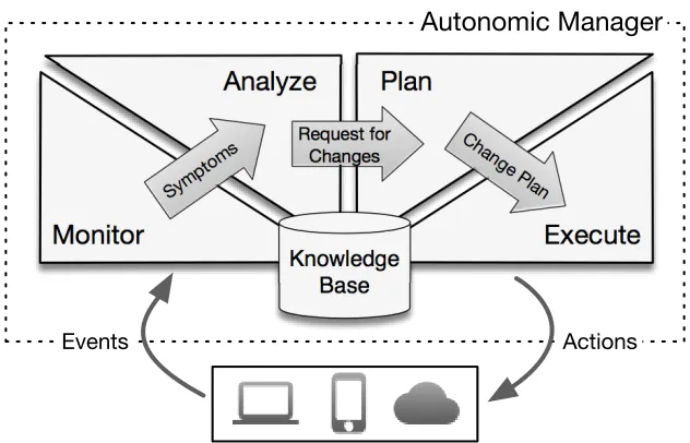
Autonomic computing aims to build computing systems that can manage themselves based on high-level objectives determined by system administrators [91].
The essence of autonomic computing isself-management. Theoretically, self-management frees system administrators from the burden of operating and maintaining complex computing systems, while keeping their performance optimal. Self-management is composed of four main aspects:
• Self-configuration: autonomic systems can configure themselves in dynamic
environ-ments, finding services and providers that they depend on and broadcasting their capa-bilities.
• Self-optimization: autonomic systems can monitor their performance and workload,
searching for opportunities to fine-tune internal parameters. Moreover, they can update these parameters, test for improvements, and rollback unsuccessful changes.
• Self-healing: autonomic systems can diagnose failures and defects and isolate
![Figure 2.10: Kubernetes architecture (adapted from Google [63]).](https://thumb-us.123doks.com/thumbv2/123dok_us/7727870.1264768/42.612.148.485.75.288/figure-kubernetes-architecture-adapted-from-google.webp)