Stacked Conical-Cylindrical Hybrid Dielectric Resonator Antenna
for Improved Ultrawide Bandwidth
Ali A. Al-Azza1, *, Nuhad A. Malalla2, Frances J. Harackiewicz3, and Kiyun Han4
Abstract—Conical and cylindrical dielectric resonator elements are vertically stacked and excited by a simple coaxial monopole. Compared to all earlier configurations, the proposed geometry significantly improves the impedance bandwidth. The ultrawideband response is enhanced due to the multiple resonances occurring by the suggested hybrid antenna. The footprint area of the antenna is only 63.6 mm2or 25.44×10⁻³λ2oat the lowest operating frequency. The performance of the antenna is verified experimentally and numerically. Presented results show that the proposed hybrid monopole-DRA has a measured impedance bandwidth up to 148.6% (S11 < −10 dB) along with consistent monopole-like
radiation patterns and peak gain of 7.14 dBi. With such properties, the proposed hybrid monopole-DRA can be used in different ultra-wideband wireless applications and as wideband electromagnetic interference (EMI) sensors.
1. INTRODUCTION
Different basic dielectric resonator antennas (DRAs) are reported in the literature such as hemispherical, cylindrical, and rectangular DRAs [1–3]. The main drawback of these basic DR antennas is the narrow bandwidth. For a standard rectangular DRA, up to 10% impedance bandwidth can be achieved [4]. Many approaches have been used to enhance the bandwidth of DRA. One of the approaches to widen the impedance bandwidth is to remove portions from DRA structure. In [4], the central portion of the rectangular DRA is removed which enhanced the bandwidth up to 28%. Another method to improve the bandwidth is to modify the geometry of the DRA to get different shapes such as a split cylinder [5], conical DRA [6], a tetrahedron and triangular [7], truncated tetrahedron [8]. These modified geometries have more degree of freedom for the design parameters than all basic DRAs geometries. By using this approach, the largest bandwidth reported so far is 72% using U-shaped DRA covering frequency ranges from 3.87 to 8.17 GHz [9]. Another approach is investigated by using hybrid DRAs. In a hybrid DRA, combination of a DRA with other resonators such as microstrip patch, quarter wave monopole MP, or a slot radiator is used to improve the impedance bandwidth. Multiple modes of the resonators are excited and merged at adjacent frequencies [10–13]. In [13], a fractional bandwidth of 3 : 1 (100%) is demonstrated by using a hybrid configuration of quarter wave electric monopole and annular DR. The monopole (MP) in this configuration is used as an exciting element for the DR and as a loaded radiating structure. The ultra-wideband response of this configuration was characterized by three resonances. The quarter-wave resonance of the MP is responsible for the lowest resonance frequency of the impedance bandwidth whereas the excitation of the TM01δ mode of the DR is generated the highest resonance.
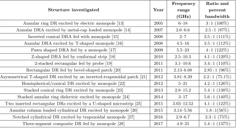
The intermediate resonance is caused by the combined effect of the MP and DR. Table 1 summaries the widest impedance bandwidth hybrid DRA reported in the literature up to date.
Received 10 August 2018, Accepted 28 September 2018, Scheduled 18 October 2018
* Corresponding author: Ali A. Al-Azza (alieng@siu.edu).
Table 1. Wideband hybrid DRA performance reported in the literature.
Structure investigated Year
Frequency range (GHz)
Ratio and percent bandwidth
Annular ring DR excited by electric monopole [13] 2005 6–18 3 : 1 (100%) Annular DRA excited by metal-cap loaded monopole [14] 2007 2.6–6.6 2.5 : 1 (87%) Inverted conical DRA fed with monopole [15] 2008 2–7 3.5 : 1 (111%)
Annular DRA excited by T-shaped monopole [16] 2008 4.5–16 3.5 : 1 (112%) Pawn shaped DRA fed by a monopole [17] 2009 5.5–23 4 : 1 (122%) Z-shaped DRA fed by conformal strip [18] 2010 2.5–10.3 4.1 : 1 (120%)
2-stacked rectangular fed by probe [19] 2011 3.1–10.6 3.4 : 1 (110%) Rectangular DR fed by bevel-shaped patch [20] 2011 2.13–6.08 2.85 : 1 (96%) Asymmetrical T-shaped DR excited by an inverted-trapezoidal patch [21] 2012 3.81–8.39 2.2 : 1 (75.1%)
Hemispherical/conical DR excited by monopole [22] 2012 5–21 4.2 : 1 (126%) Stacked conical ring DR excited by monopole [23] 2013 2.8–15.2 5.4 : 1 (138%) Stacked annular ring dielectric excited by monopole [24] 2014 3–17 5.6 : 1 (140%)
Two inserted rectangular DRs excited by a U-shaped microstrip [25] 2015 3.03–12.52 4.1 : 1 (122%) Annular column loaded cylindrical DR excited by monopole [26] 2015 3.14–5.56 1.8 : 1(56%)
Notched cylindrical DR excited by trapezoidal monopole [27] 2016 2.9–6.7 2.3 : 1 (75%)
Three-segment composite DR fed by monopole [28] 2017 4.9–25 5.4 : 1 (137%)
In this paper, a new hybrid DRA configuration will be used to increase the impedance bandwidth of the antenna. Compared to earlier studies in the open literature [23–28], the proposed configuration results in multiple nearby resonant modes which explain the further substantial bandwidth enhancement. A measured fractional bandwidth about 148.6% (6.8 : 1) is obtained with a consistent monopole like radiation over the operating bandwidth and a peak gain of 7.14 dBi.
The 3D electromagnetic simulation software, Computer Simulation Technology (CST), is used to simulate the proposed configuration and followed by experimental verifications. The observational frequency range is extended up to 35 GHz. In addition, the simulated results are compared with the measured ones of the fabricated antenna loaded with lossy DRs, and a good agreement is revealed.
2. ANTENNA CONFIGURATION
The proposed antenna configuration is shown in Fig. 1. The antenna structure consists of vertically stacked annular conical-cylindrical DRs excited by a coax-fed cylindrical monopole with length (l). The radius (r) of the MP is 0.65 mm which is the probe’s radius of the Pasternack’s PE4434 commercial SMA connector. The ceramic material with permittivity equal to 10 is used in designing and fabricating the DR elements. Other materials with permittivity values higher than 10 could have also been selected. However, the radiation and bandwidth of the antenna are degraded with such higher values of the dielectric constant.
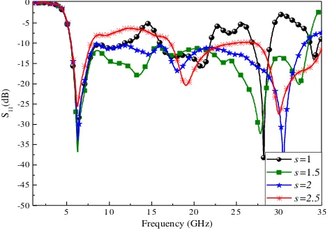
The spacing (s) between the monopole and the DR structures controls the coupling between the two elements. It is found that selecting higher values of s deteriorates the performance as shown in Fig. 2. The best choice is found within the following range: 2r < s <3r which is between 1.3 mm and 1.95 mm.
As starting point, the bottom radius (ra) of the cone DR (CoDR) is determined according to the following equation [22]:
ra(in mm) = 47.713×Re{Koa}/fr (1)
SMA connector
l
h1
h2
2s
electric monopole
ground plane
z
x
y x
2r central cut-out
d1
2ra
2rb
Figure 1. Proposed antenna configuration.
5 1 0 1 5 2 0 2 5 30 35
-50 -45 -40 -35 -30 -25 -20 -15 -10 -5 0
s=1
s=1.5
s=2 s=2.5
S11
(d
B
)
Frequency (GHz)
Figure 2. Effect of the variation of spacing (s) in mm on the S11 of the antenna.
5 1 0 1 5 2 0 2 5 3 0 3 5
-50 -45 -40 -35 -30 -25 -20 -15 -10 -5 0
l=9
l=10
l=11
l=12 S11
(d
B
)
Frequency (GHz)
Figure 3. Simulated S11 plot of the for different
probe length (l) in mm.
theKoa, which is a function of permittivity [3]. For ceramic material withr= 10, Re{Koa}= 1.42090. Next, the height of CoDR is determined as h1 =
r2
a−s2.
The parameters of the cylindrical DR which include the height (h2) and the radius (rb) can be
determined as [29]:
0.4l≤h2≤0.5l
rb = (s+r)/0.3 (2)
Table 2. Geometry details in millimeters of the proposed design.
l h1 h2 r s d1 rb ra
11 3 5 0.65 1.5 4 3 4.5
3. SIMULATIONS AND MEASUREMENTS
The bandwidth response of the proposed antenna has multiple resonances labeled as f1–f7. These
resonant frequencies have been identified in Fig. 4. Different individual cases are examined for better understanding the principle of operation of the antenna. First, a stand-alone MP is contributed by three resonances. The first one relates to the quarter wave dominant mode of the MP which coincides with f1, and it occurs near 6 GHz. The first higher order mode of the MP resonates at 18 GHz which
is close to f4 (17.7 GHz). The MP second higher order mode occurs at 31 GHz which is shifted to f6
(27.5 GHz) due to the DR loading effect of the proposed antenna.
In the second case, the DR alone is excited, and two resonances are obtained. The first resonance is the fundamental TM01δ mode of the DR which exactly matches withf5 (23 GHz). The second resonant
frequency (near 34 GHz) is the first higher order mode of the DR which indicates its closeness to f7
(32 GHz).
Study of a sequential loading of the MP with conical and cylindrical DRs is performed as shown in Fig. 5 to identify f2 and f3. Loading the MP with CoDR enhanced the bandwidth from 18 GHz to
31.7 GHz due to the overlapping among f4, f5, and f6. Till now, no hints for f2 and f3 are revealed.
After adding the cylindrical DR as a top loading for MP-CoDR configuration, the impedance matching in the lower frequency range from 7.5 GHz to 17 GHz is enhanced due to the occurrence of f2 and f3
at 10.5 and 13.4 GHz, respectively. Moreover, the bandwidth range is enhanced up to 33.3 GHz due to occurrence of f7.
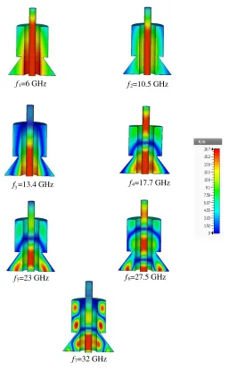
TheH-field vectors at different resonant frequencies are shown in Fig. 6. At each frequency of f1,
f4, and f6, there is minimal coupling between the monopole and DR, and the magnetic field inside the
DR appears very weak. The proposed antenna behaves as a conventional monopole antenna. For f2
and f3, the DR structure loads the MP in such a way that the current distribution in the MP turns
it to a quarter-wave MP with a reduced effective length (leq < l). The MP has effective length about 0.65land 0.5l atf2 andf3, respectively. The field is predominantly prominent in the DR atf5 showing
TM01δ resonant mode. Atf7, the current is concentrated in the DR, and the field shows a higher order
mode excitation in the DR.
To further investigate the phenomenon behind these multiple resonances, a simulation study of the
5 1 0 1 5 2 0 2 5 3 0 3 5
-50 -45 -40 -35 -30 -25 -20 -15 -10 -5 0
f7
f6
f5
f4
f3
f2
S11
(d
B
)
Frequency (GHz) MP
MP-CoDR
Proposed
f1
Figure 4. Return loss characteristics of: MP, DR excitation only, and proposed antennas.
5 1 0 1 5 2 0 2 5 3 0 3 5
-45 -40 -35 -30 -25 -20 -15 -10 -5 0
f 7 f3
f2
S11
(d
B)
Frequency (GHz) MP
Co DR
f1=6 GHz f2=10.5 GHz
f5=23 GHz f6=27.5 GHz
f7=32 GHz
f3=13.4 GHz f4=17.7 GHz
Figure 6. Simulated magnetic field distributions in the elements of the proposed antenna to examine the nature of resonant modes of the return loss.
current distributions along the MP of the proposed antenna is presented in Fig. 7. It is clear from the current distributions that the monopole behaves as a quarter wave monopole at 10.5 and 13.4 GHz due to the coupling effect of the DR while it is almost full wavelength long at 27.5 GHz.
To validate the simulation results, a prototype of the proposed hybrid DRA is fabricated and verified experimentally. A few drops of synthetic glue are used to fix the DR structure on the ground plate. Fig. 8 shows a photograph of fabricated hybrid DRA. The HP 8510C vector network analyzer is used to measure the return loss over frequency range 1 to 35 GHz.
The variations of the simulated and measured return losses versus frequency for the antenna are simultaneously depicted in Fig. 9. It can be observed that there is a good agreement between the simulated and measured data. A measured fractional bandwidth about 148.6% (6.8 : 1) covering the frequency range from 5.1 to 34.6 GHz is obtained. The proposed antenna achieves wider impedance bandwidth than all the ultra-wideband hybrid DRAs listed in Table 1.
0. 0 0 .2 0. 4 0 .6 0. 8 1 .0 0 5 10 15 20 25 30 C u rr e n t ma gnitude ( m A)
z / l 6 GHz 10.5 GHz 13.4 GHz 17.7 GHz 23 GHz 27. 5 32 GHz
Figure 7. Current magnitudes along the MP at different resonant frequencies.
DR MP
Figure 8. Prototype fabricated antenna.
5 1 0 1 5 2 0 2 5 3 0 3 5
-25 -20 -15 -10 -5 0 S11 (d B ) Frequency (GHz) Simulated Measured
Figure 9. Simulated and the measured return loss for the proposed antenna.
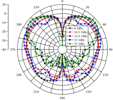
0 30 60 90 12 0 15 0 180 21 0 240 270 300 33 0 -40 -30 -20 -10 0 10
6 GHz 10.5 GHz 13.4 GHz 23 GHz 32 GHz
Figure 10. Gain patterns of the proposed antenna along thexz-plane at different frequency points.
-80 -60 -40 -20 0 2 0 4 0 6 0 8 0
-40 -35 -30 -25 -20 -15 -10 -5 0 5 10 Gain (dBi) Angle (degree) simulat ed measured
±48–52◦.
Figure 11 shows a comparison between the simulated and measured gains as a function of the elevation angle at 10.5 GHz. As shown in the figure, a good agreement between them is revealed.
The proposed antenna achieves wider impedance bandwidth than all recent ultra-wideband hybrid DRAs [23–28]. The proposed antenna achieves an improvement in the bandwidth by 8.6% compared to the widest impedance bandwidth hybrid DRA reported in the literature till now [24]. Moreover, the footprint area of the proposed antenna is just 63.6 mm2 compared to the 425 mm2 reported in [28].
4. CONCLUSION
A new wideband hybrid monopole-dielectric resonator antenna has been proposed. The principle of the antenna operation is thoroughly studied using theoretical and experimental data. A commercial SMA probe is all what is needed to excite the proposed antenna. Impedance bandwidth of 148.6% with 7.14 dBi peak gain and consistent monopole-like radiation pattern are achieved from an antenna that has 63.6 mm2 footprint area and height of 11 mm. The compact size, easy excitation, wide impedance bandwidth, and relatively high gain are considered the major features that make this antenna a new member in the family of monopole-DRA antennas.
REFERENCES
1. McAllister, M. W. and S. A. Long, “Resonant hemispherical dielectric antenna,” Electron. Lett., Vol. 20, No. 16, 657–659, 1984.
2. Luk, K. M. and K. W. Leung,Dielectric Resonator Antennas, Research Studies Press Ltd., England, 2003.
3. Petosa, A., Dielectric Resonator Antenna Handbook, Artech House, Norwood, MA, USA, 2007. 4. Guillon, P. and Y. Garault, “Accurate resonant frequencies of dielectric resonators,” IEEE Trans.
Antennas Propag., Vol. 25, No. 11, 916–922, Nov. 1977.
5. Kishk, A. A., A. W. Glisson, and G. P. Junker, “Bandwidth enhancement for split cylindrical dielectric resonator antennas,”Progress In Electromagnetics Research, Vol. 33, 97–118, 2001. 6. Kishk, A. A. and A. W. Glisson, “Conical dielectric resonator antennas for wide-band applications,”
IEEE Trans. Antennas Propag., Vol. 50, No. 4, 469–474, Apr. 2002.
7. Kishk, A. A., “Tetrahedron and triangular dielectric resonator with wideband performance,”Proc. IEEE AP-S Int. Symp. Dig., Vol. 4, 462–465, Jun. 2002.
8. Kishk, A. A., “Wide-band truncated tetrahedron dielectric resonator antenna excited by a coaxial probe,” IEEE Trans. Antennas Propag., Vol. 51, No. 10, 2913–2917, 2003.
9. Zhang, L. N., S. S. Zhong, W. Shen, and X. Yang, “Wideband U-shaped dielectric resonator antenna,” European Conferenceon Antennas and Propagation EuCAP 2009, 2361–2364, Berl in, Germany, Mar. 2009.
10. Li, B. and K. W. Leung, “Strip-fed rectangular dielectric resonator antennas with/without a parasitic patch,”IEEE Trans. Antennas Propag., Vol. 53, No. 7, 2200–2207, Jul. 2005.
11. Young, C. S. D. and S. A. Long, “Wideband cylindrical and rectangular dielectric resonator antennas,”IEEE Antennas Wireless Propag. Lett., Vol. 5, 426–429, 2006.
12. Liang, X., T. A. Denidni, and L. Zhang, “Wideband L-shaped dielectric resonator antenna with a conformal inverted-trapezoidal patch feed,” IEEE Trans. Antennas Propag., Vol. 57, No. 1, 271– 274, Jan. 2009.
13. Lapierre, M., Y. M. M. Antar, A. Ittipiboon, and A. Petosa, “Ultra wide-band monopole/dielectric resonator antenna,” IEEE Microw. Wireless Compon. Lett., Vol. 15, No. 1, 7–9, Jan. 2005.
14. Thirakoune, S., A. Petosa, and A. Ittipiboon, “Yagi-like DRA-loaded monopole,” Proc. ICEAA, 891–894, 2007.
16. Ghosh, S. and A. Chakrabarty, “Ultrawideband performance of dielectric loaded T-shaped monopole transmit and receive antenna/EMI sensor,” IEEE Antennas Wireless Propag. Lett., Vol. 7, 358–361, 2008.
17. Guha, D., B. Gupta, and Y. Antar, “New pawn-shaped dielectric ring resonator loaded hybrid monopole antenna for improved ultra-wide bandwidth,” IEEE Antennas Wireless Propag Lett., Vol. 8, 1178–1181, 2009.
18. Denidni, T. A., Z. Weng, and M. Niroo-Jazi, “Z-shaped dielectric resonator antenna for ultrawideband applications,”IEEE Trans. Antennas Propag., Vol. 58, 4059–4063, 2010.
19. Ge, Y., K. P. Esselle, and T. S. Bird, “Compact dielectric resonator antennas with ultrawide 60–110% bandwidth,”IEEE Trans. Antennas Propag., Vol. 59, No. 9, 3445–3448, 2011.
20. Khalily, M., M. K. A Rahim, and A. A. Kishk, “Bandwidth enhancement and radiation characteristics improvement of rectangular dielectric resonator antenna,”IEEE Antennas Wireless Propag. Lett., Vol. 10, 393–395, 2011.
21. Gao, Y., Z. Feng, and L. Zhang, “Compact asymmetrical T-shaped dielectric resonator antenna for broadband applications,” IEEE Trans. Antennas Propag., Vol. 60, No. 3, 1611–1615, Mar. 2012. 22. Guha, D., B. Gupta, and Y. M. M. Antar, “Hybrid monopole-DRAs using
hemispherical/conical-shaped dielectric ring resonators: Improved ultrawideband designs,” IEEE Trans. Antennas Propag., Vol. 60, No. 1, 393–398, Jan. 2012.
23. Ozzaim, C., F. Ustuner, and N. Tarim, “Stacked conical ring dielectric resonator antenna excited by a monopole for improved ultrawide bandwidth,”IEEE Trans. Antennas Propag., Vol. 61, No. 3, 1435–1438, Mar. 2013.
24. Ozzaim, C., “Monopole antenna loaded by stacked annular ring dielectric resonators for ultrawide bandwidth,”Microw. Opt. Technol. Lett., Vol. 56, No. 10, 2395–2398, 2014.
25. Abedian, M., S. K. A. Rahim, S. Danesh, S. Hakimi, L. Y. Cheong, and M. H. Jamaluddin, “Novel design of compact UWB dielectric resonator antenna with dual-band-rejection characteristics for WiMAX/WLAN bands,”IEEE Antennas Wireless Propag. Lett., Vol. 14, 245–248, 2015.
26. He, Y., Y. Lin, C. Deng, and Z. Feng, “Annular column loaded cylindrical dielectric resonator antenna for wideband conical radiation,” IEEE Trans. Antennas Propag., Vol. 63, No. 12, 5874– 5878, Dec. 2015.
27. Li, X., Y. Yang, F. Gao, H. Ma, and X. Shi, “A compact dielectric resonator antenna excited by a planar monopole patch for wideband applications,” International Journal of Antennas and Propagation, Vol. 2016, No. 3, 1–9, 2016.
28. Guha, D., D. Ganguly, S. George, C. Kumar, M. Sebastian, and Y. M. M. Antar, “A new design approach for a hybrid monopole to achieve increased ultrawide bandwidth,” IEEE Antennas and Propagation Magazine, Vol. 59, No. 1, 139–144, Feb. 2017.