Three-Port Pattern Diversity Antenna Module for 5.2 GHz
Ceiling-Mounted WLAN Access Points
Somanatha Swapna, Gulur S. Karthikeya, Shiban K. Koul, and Ananjan Basu
Abstract—In this paper, a three-port pattern diversity antenna with a Fabry-Perot cavity (FPC) using a partially reflective surface (PRS) for 5.2 GHz Wireless Local Area Network (WLAN) access points is proposed. The topology of three coaxial-fed circular patch antennas provides an initial beam tilt of 15◦. The PRS aperture, at a height of approximately λ/2, is then shaped in such a way for the antenna to radiate at 0◦,+25◦,−25◦, which results in total coverage of 90◦. The antenna system has an impedance bandwidth of 2% ranging from 5.16 GHz to 5.25 GHz (90 MHz bandwidth), covering the IEEE 802.11a band, for a gain of 10 dBi throughout the band and across the ports. The shaped PRS structure provides a gain enhancement of 4.5 dB. The mutual coupling between any two ports in the three-port antenna system is less than 20 dB for a port-to-port distance of 0.67λ.
1. INTRODUCTION
In recent years pattern diversity has gained noteworthy scrutiny from antenna researchers due to their potential for improved performance in wireless communication systems [1]. The rapid pace of development in the state of the art communication systems has opened up a wide range of application areas for pattern diversity antennas, including wireless communication, radar applications, and mobile communication. A diverse range of pattern diversity antennas has been reported in the literature. A three-port antenna with pattern diversity at 0◦,+90◦,−90◦ is proposed in [2]. But the antennas have very low gain with port-to-port gains varying between 1 dBi and 3.8 dBi. A three-port antenna with patterns aiming at 0◦,120◦,240◦ is proposed in [3]. The peak gain of the patterns is only 2.3 dBi which is very low for access point antennas. [4] and [5] proposed two-port patch antennas that radiate conical and broadside beams. But it consists of rat race feeding network and power dividers that make the design complex in addition to the increased insertion loss. Besides, there is little control over the conical patterns radiated by the patch. Researchers in [6] proposed a ring antenna with omnidirectional and broadside pattern diversity. The design is intricate with three power dividers and provides a gain of 3.8 dBi.
To achieve high gain for antennas, a lot of research is reported today on Fabry-Perot cavity (FPC) antennas [7]. Pattern diversity along with the FPC action has a lot of research potential as it can facilitate high gains with a low footprint. Researchers in [8] steered the beam by 12◦ on either direction from the broadside by individually magnetizing the ferrite cylinders which might be challenging to realize in a commercial module. A beam steering FPC antenna with reconfigurable partially reflecting surface (PRS) is proposed in [9]. The antenna achieves a beam tilt of only 10◦ and the PRS uses 144 diodes to achieve this tilt. A circularly polarized FPC antenna fed by a linearly polarized microstrip patch aligned along 45◦ and integrated with an artificial magnetic conductor (AMC) surface is proposed in [10]. It can tilt only to one direction, and the narrow beam of the antenna offers only 45◦ angular coverage.
Received 16 October 2019, Accepted 15 December 2019, Scheduled 22 December 2019
In this paper, we present a three-element pattern diversity antenna with a high gain for an operating frequency of 5.2 GHz. The radiation pattern of the antenna switches between 0◦,+25◦,−25◦ with an angular coverage of 90◦. The 90◦coverage of the antenna is based on the 3 dB beamwidth of the antenna radiation pattern, considering the 3 dB points of antenna 2 and 3. The shaped aperture of the partially reflecting surface (PRS) is designed to increase the gain of the antenna equally irrespective of the angle of illumination. The literature study of the FPC antennas shows that the present day designs of FPC antennas are under normal incidence of em waves. This paper looks into the FPC designs on gain enhancement under normal and oblique incidence as well.
2. ANTENNA DESIGN AND ANALYSIS
2.1. Three Element Antenna Design
Figure 1 shows the three-element patch antenna design. The antennas are fabricated on Rogers RO4350B substrate with dielectric constant r = 3.66, thickness of 20 mil and tanδ = 0.0037. The ground plane has an area of 142 ×60 mm2 (2.4λ×1λ) where λ is free-space wavelength at 5.2 GHz. The three antennas are coaxially fed with a port-to-port distance of 0.67λ. The coaxial feed allows elimination of the transmission line insertion loss, which reduces the aperture efficiency as the transmission line cannot radiate and the PRS placed above the transmission line is redundant. So a higher aperture efficiency is achieved by using the coaxial feed.
(a)
(b)
Figure 1. Schematic of three element antenna. (a) Top view. (b) Side view.
The simulated and measured input reflection coefficients are shown in Fig. 2. The simulated impedance bandwidth for the antenna is 90 MHz (5.17 GHz–5.26 GHz). The half-power beamwidth (HPBW) of the antenna 1 is 36◦ and that of antenna 2 and 3 is 65◦. The front-to-back ratio of antenna 1 is 18 dB and of antenna 2 and 3 is 20 dB due to an electrically large ground plane. The gain of antenna 1 as shown in Fig. 3 is 6 dBi and that of antenna 2 and 3 is 5.7 dBi along with a tilt of +15◦,−15◦. The pattern of antenna 2 and 3 are tilted due to the mutual coupling between the antennas at a distance of 0.6λbetween the input ports.
A PRS superstrate for a Fabry Perot cavity resonance is now designed to enhance the gain equally across the band and throughout the ports of the antenna.
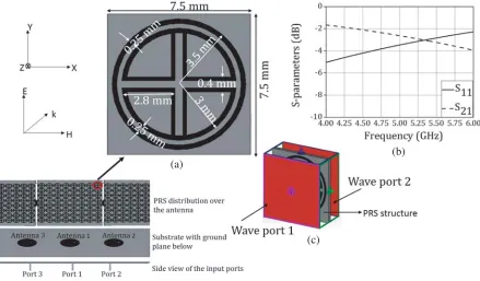
2.2. Design and Analysis of Unit-Cell
(a) (b)
Figure 2. Input reflection coefficients of the three patch antennas. (a) Simulation. (b) Measurement.
(a) (b)
Figure 3. Gain of the three patch antennas. (a) Simulation. (b) Measurement.
(a)
(b)
(c)
and S21 = −2.9 dB at the operating frequency of 5.2 GHz. The substrate used is Rogers RO4350B
with dielectric constant,r= 3.66, 20 mil thickness and tanδ= 0.0037. The substrate for the PRS was chosen to be the same as that of the antenna to ensure continuity and to have homogenous properties for the entire structure. The PEC, PMC boundary conditions were assigned in theXZ- andY Z-planes of the unit-cell to extract the S-parameters. The two ports are assigned in thez-direction. The full-wave EM simulation software CST Microwave Studio is used to extract the parameters of the unit-cell. A superstrate with periodic unit-cells is then designed to be integrated above the patch. The PRS and the ground plane creates a cavity where the EM waves undergo multiple reflections. The PRS is designed in such a way that a part of the reflections get transmitted out of the cavity, which happens as the value of S21 is −2.9 dB. The waves transmitted out of the cavity should sustain a constructive interference
which then gets added up and boosts the gain of the antenna in a specific direction [11].
2.3. Proposed three Element Antenna Design after Unit-Cell Loading
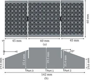
Figure 5 shows the proposed design consisting of three patch antennas integrated with a shaped PRS. The antennas emit electromagnetic waves which undergo multiple reflections inside the cavity formed by the PRS and the ground plane. These multiple reflections results in gain enhancement of the antenna [12–14]. The PRS is placed at a distance of approximatelyλ/2 above the patch for port 1 for boresight gain enhancement.
(a)
(b)
Figure 5. (a) The shaped PRS aperture arrangement. (b) Side view of the arrangement with respect to the three input ports.
designs are planar in structure which is inadequate for beam tilting. Here a structure that acts as a Fabry Perot cavity with different tilt angles and different heights for the PRS is used. The tilted superstrates ensure a higher phase correction to the em waves than a planar structure for the beam shifted. For each case, the beam tilt obtained along with the resulting gain was noted down. From the observations, it was clear that at an angle of 20◦ the antenna 2 and 3 of the FPC provided a beam tilt of 25◦ for a gain of 10 dB throughout the band. Further increase in angular tilt made the gain of the antennas to reduce. This happens as the height of the superstrate will become so low that proper resonance is not possible. A similar angular tilt gave to the antennas by physically keeping them at +25◦ and−25◦ resulted in detuning of the antennas.
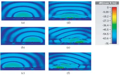
The electric field distribution before and after the PRS loading is shown in Fig. 6. The shaped PRS, especially the tilted PRS, re-orients the electric field of the leaky waves which subsequently results in the beam tilt. The PRS makes the phase correction wavefront to be planar compared to the unloaded
(a)
(b)
(c)
(d)
(e)
(f)
Figure 6. Electric field distribution for the three ports. (a), (b), (c) Before shaped PRS integration (d), (e), (f) after shaped PRS integration.
(a) (b)
antenna which reduces the beam width and enhances the gain.
For each port, the simulated and measured input reflection coefficients are as shown in Fig. 7. The simulated impedance bandwidth of the proposed antenna is 90 MHz (5.16 GHz–5.25 GHz). This shows that the impedance bandwidth of the proposed antenna does not get altered after the superstrate integration. The height of the FPC is designed such that the resonance of the cavity can be merged to the patch antennas. Thus the resonant frequency of the three antennas does not change post-PRS integration. This helps in achieving the design objective of higher gain at the impedance bandwidth of the three antennas. Another advantage is that the FPC separates the feed antennas and the PRS structures making it convenient to expand the design to further ports or multiple PRS layers. The
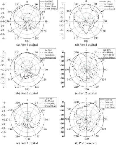
(a) Port 1 excited
(b) Port 2 excited
(c) Port 3 excited
(d) Port 1 excited
(e) Port 2 excited
(f) Port 3 excited
simulated half-power beamwidth of antenna 1 is 23◦ with a front-to-back ratio of 12 dB and that of antenna 2 and 3 is 30◦ and 16 dB.
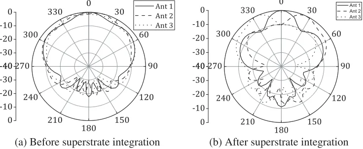
The radiation patterns of the antenna before and after the superstrate loading are shown in Fig. 8. The radiation pattern of the antenna indicates an intersection of 3-dB patterns which then provides a coverage of 90◦ as shown in Fig. 9. The superstrate loading does not alter the polarization of the three antennas and thus it maintains the polarization integrity of the unloaded antennas.
Figure 10 shows the gains of the three antennas after the shaped PRS integration, and Fig. 11
(a) Before superstrate integration (b) After superstrate integration
Figure 9. (a) Angular coverage before superstrate loading. (b) Angular coverage post superstrate integration.
(a) (b)
Figure 10. Gain of the antenna after PRS loading. (a) Simulation. (b) Measurement.
(a) (b)
shows the gain enhancement of 4.5 dB with respect to the antenna without the shaped PRS integration. Figs. 12 and 13 give the mutual coupling of the antennas between the ports before and after the PRS integration. The antennas maintain an isolation of 20 dB between the ports post-integration as shown
(a) (b)
Figure 12. Mutual coupling of the antenna before PRS loading.
(a) (b)
Figure 13. Mutual coupling of the antenna after PRS loading.
(a)
(b)
in Fig. 13. The proposed antenna with 10 dBi gain is an improvement over the commercial antenna for access points in [18] for a 90◦ coverage. The height of the antenna at the center is only 39.5 mm which is lower than the height of 55 mm for the commercial antenna.
A prototype of the proposed antenna has been fabricated as shown in Fig. 14 to validate the simulation results. The antenna is fabricated by the photolithographic process while the scaffolding needed to keep the shaped PRS superstrate in place is 3D printed. The 3D printing was performed using a Raise 3D RxP2200 3D printer with the polymer polylactic acid (PLA) material which is used in commercial low budget 3D printing. Anritsu MS2028C was used to measure theS-parameter of the antenna and the far-field measurements are conducted inside an anechoic chamber. The ETS-Lindgreen 3115 Model double ridged waveguide horn antenna was used as the standard gain antenna for the measurement.
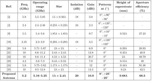
The performance of the proposed antenna is compared with the existing designs in the literature and is tabulated in Table 1. The proposed antenna provides a very high gain for the coverage of 90◦ in the broadside direction which is higher than the existing designs.
Table 1. Comparison of the proposed structure.
Ref. Freq (GHz) Operating range (GHz) Size Isolation (dB) Gain (dBi) Patterns at (◦)
Height of superstrate (mm) Aperture efficiency (%)
[2] 5.8 5.5–5.85 1λ×0.56λ 18 3.8 0◦,+90◦
−90◦ – –
[3] 2.4 2.4–2.48 0.23λ×0.23λ 24 2.3 0◦,+120◦,
−120◦ – –
[9] 5.5 5.4–5.6 1.85λ×1.85λ – 9.7 0◦,+10◦
−10◦ 0.52λ 27.23
[19] 2.45 2.3–3.9 0.29λ×0.29λ 18 3.5 0◦,+120◦
−120◦ – –
[20] 5.8 5.71–5.87 2λ×2λ - 6.9 0◦ 0.39λ 28.93
[21] 10 8.6–11.2 2.4λ×2.4λ – 13.8 0◦ 0.45λ 40.9
[22] 10 8.6–11.4 4.3λ×4.3λ – 20.7 0◦ 2λ 49.79
[23] 4.2 3.8–7.3 0.4λ×0.3λ – 7.0 0◦ 0.15λ 48
[24] 5.8 5.75–5.82 1.17λ×1.17λ – 12 0◦ 0.44λ 91.46
[25] 10 9.5–12.8 2λ×2λ – 13.4 0◦ 0.2λ 43.5
Proposed
Antenna 5.2 5.16–5.25 1λ×2.4λ 20 10.0
0◦,+25◦
−25◦ 0.68λ 68.5
3. CONCLUSION
A three-port pattern diversity FPC antenna with shaped aperture PRS is proposed. The PRS is tilted by an angle of 20◦ above the two patches to obtain a 25◦ beam tilt with 10 dB gain for the three antennas. The PRS contributes a 4.6 dB gain enhancement to the three patch antennas. A prototype antenna is fabricated and measured. The simulated and measured results are in agreement with each other that confirms the correctness of the design.
REFERENCES
2. Sharma, Y., D. Sarkar, K. Saurav, and K. V. Srivastava, “Three-element MIMO antenna system with pattern and polarization diversity for WLAN applications,” IEEE Antennas and Wireless Propagation Letters, Vol. 16, 1163–1166, 2017.
3. Wang, H., L. Liu, Z. Zhang, Y. Li, and Z. Feng, “Ultra-compact three-port mimo antenna with high isolation and directional radiation patterns,” IEEE Antennas and Wireless Propagation Letters, Vol. 13, 1545–1548, 2014.
4. Cui, L., W. Wu, and D. Fang, “Wideband circular patch antenna for pattern diversity application,”
IEEE Antennas and Wireless Propagation Letters, Vol. 14, 1298–1301, 2015.
5. Sun, L., G. Zhang, B. Sun, W. Tang, and J. Yuan, “A single patch antenna with broadside and conical radiation patterns for 3g/4g pattern diversity,” IEEE Antennas and Wireless Propagation Letters, Vol. 15, 433–436, 2016.
6. Saurav, K., N. K. Mallat, and Y. M. M. Antar, “A three-port polarization and pattern diversity ring antenna,” IEEE Antennas and Wireless Propagation Letters, Vol. 17, No. 7, 1324–1328, Jul. 2018. 7. Chacko, B. P., G. Augustin, and T. A. Denidni, “FPC antennas: C-band point-to-point communication systems,” IEEE Antennas and Propagation Magazine, Vol. 58, No. 1, 56–64, Feb. 2016.
8. Sultan, F. and S. S. I. Mitu, “Superstrate-based beam scanning of a Fabry-Perot cavity antenna,”
IEEE Antennas and Wireless Propagation Letters, Vol. 15, 1187–1190, 2016.
9. Xie, P., G. Wang, H. Li, and J. Liang, “A dual-polarized two-dimensional beam-steering Fabry-P´erot cavity antenna with a reconfigurable partially reflecting surface,” IEEE Antennas and Wireless Propagation Letters, Vol. 16, 2370–2374, 2017.
10. Liu, Z., Z. Cao, and L. Wu, “Compact low-profile circularly polarized Fabry-Perot resonator antenna fed by linearly polarized microstrip patch,” IEEE Antennas and Wireless Propagation Letters, Vol. 15, 524–527, 2016.
11. Costa, F., D. Bianchi, A. Monorchio, and G. Manara, “Linear Fabry-Perot/leaky-wave antennas excited by multiple sources,” IEEE Transactions on Antennas and Propagation, Vol. 66, No. 10, 5150–5159, Oct. 2018.
12. Pan, W., C. Huang, P. Chen, X. Ma, C. Hu, and X. Luo, “A low-RCS and high-gain partially reflecting surface antenna,”IEEE Transactions on Antennas and Propagation, Vol. 62, No. 2, 945– 949, Feb. 2014.
13. Vaidya, A. R., R. K. Gupta, S. K. Mishra, and J. Mukherjee, “Right-hand/left-hand circularly polarized high-gain antennas using partially reflective surfaces,” IEEE Antennas and Wireless Propagation Letters, Vol. 13, 431–434, 2014.
14. Ren, J., W. Jiang, K. Zhang, and S. Gong, “A high-gain circularly polarized Fabry-Perot antenna with wideband low-rcs property,”IEEE Antennas and Wireless Propagation Letters, Vol. 17, No. 5, 853–856, May 2018.
15. Konstantinidis, K., A. P. Feresidis, and P. S. Hall, “Multilayer partially re ective surfaces for broadband Fabry-Perot cavity antennas,” IEEE Transactions on Antennas and Propagation, Vol. 62, No. 7, 3474–3481, Jul. 2014.
16. Zheng, Y., J. Gao, Y. Zhou, X. Cao, H. Yang, S. Li, and T. Li, “Wideband gain enhancement and rcs reduction of Fabry-Perot resonator antenna with chessboard arranged metamaterial superstrate,”
IEEE Transactions on Antennas and Propagation, Vol. 66, No. 2, 590–599, Feb. 2018.
17. Guzm´an-Quir´os, R., A. R. Weily, J. L. G´omez-Tornero, and Y. J. Guo, “A Fabry-P´erot antenna with two-dimensional electronic beam scanning,”IEEE Transactions on Antennas and Propagation, Vol. 64, No. 4, 1536–1541, Apr. 2016.
18. Cisco Aironet 2800 Series Access Points, Cisco, 2 2019.
19. Wang, H., L. Liu, Z. Zhang, and Z. Feng, “Wideband tri-port mimo antenna with compact size and directional radiation pattern,” Electronics Letters, Vol. 50, No. 18, 1261–1262, Aug. 2014. 20. Kim, J. H., C. Ahn, and J. Bang, “Antenna gain enhancement using a holey superstrate,” IEEE
21. Wang, N., Q. Liu, C. Wu, L. Talbi, Q. Zeng, and J. Xu, “Wideband fabry-perot resonator antenna with two complementary FSS layers,” IEEE Transactions on Antennas and Propagation, Vol. 62, No. 5, 2463–2471, May 2014.
22. Li, H., G. Wang, T. Cai, J. Liang, and X. Gao, “Phase- and amplitude-control metasurfaces for antenna main-lobe and sidelobe manipulations,”IEEE Transactions on Antennas and Propagation, Vol. 66, No. 10, 5121–5129, Oct. 2018.
23. Mao, C., Y. Yang, X. He, J. Zheng, and T. Liu, “Design of high-gain dual-band dual-circular-polarised antenna using reflective metasurface,” Electronics Letters, Vol. 53, No. 22, 1448–1450, 2017.
24. Aziz, R. S., T. Kim, J. Park, Y. Ryu, and S. Park, “EM lens design using thin planar metasurfaces for high antenna gain and low sll applications,” IET Microwaves, Antennas Propagation, Vol. 13, No. 7, 950–958, 2019.