A Low SAR Value Wearable Antenna for Wireless Body Area
Network Based on AMC Structure
Bo Yin, Jing Gu*, Xingxing Feng, Bin Wang, Youhai Yu, and Wei Ruan
Abstract—This paper proposes a wearable antenna for Wireless Body Area Network (WBAN) that operates at the 2.45 GHz medical band. The antenna is enabled by coplanar waveguide, and the impedance bandwidth of the antenna is expanded by combining a circular slot with asymmetric slots. In order to reduce the radiation of the antenna back lobe and improve the antenna gain, a new 2×2 Artificial Magnetic Conductor (AMC) is designed and loaded under the monopole antenna. The radiation of antenna back lobe is effectively reduced due to the addition of AMC reflector. Also, the front-to-back ratio of the demonstrated antenna is higher than 20 dB, achieving a forward gain of 7.47 dBi and Specific Absorption Rate (SAR) lower than 0.15 W/kg, in the ISM band. For further research, the antenna is fabricated and tested, showing a strong agreement between simulation and measurement. Meanwhile, the antenna has stable performance under the bending condition, meeting the practical application requirements of wearable equipment.
1. INTRODUCTION
Wireless Body Area Network (WBNA) is a human-centered communication network [3], taking human body as a part of the whole network [1, 2]. As a new form of the network, through WBAN, human body can communicate and synchronize by electronic devices and network terminals. In the field of health care, WBNA has a very wide range of applications. Through wireless physiological sensors, human physiological information such as blood pressure, blood sugar concentration, temperature, and heartbeat can be transmitted to medical monitoring equipment, achieving real-time remote monitoring. Wearable antenna is an important medium for data transmission in WBAN, which integrates structure and material improvement into clothing to achieve effective transmission of human body sign data [4]. Because of the great application value of wearable antennas, they have attracted the attention of scholars.
The original wearable antennas mainly use conductive fabric material with flexible characteristics as the substrate, which is conducive to be conformal with human body, also enabling the antenna to have good abrasion resistance and stable performance [5]. Later, some experts were devoted to improving the bandwidth of wearable antenna and designed a wearable antenna with ultra-wideband (UWB) characteristics covering a wider operating frequency band [6, 7], which has a wider application value in practical applications.
In contrast to general antennas, the wearable antenna used for human body is more special. In recent years, many experts and scholars have mainly researched on reducing the radiation intensity of antenna to human body [8–10]. In [11], Jiang et al. proposed a compact wearable antenna used for ISM 2.36 ∼ 2.4 GHz. By utilizing the 0◦ reflection phase characteristic of a highly truncated metasurface, the antenna has shown unidirectional characteristics, reduced coupling between antenna and human
Received 1 April 2019, Accepted 29 July 2019, Scheduled 2 September 2019
* Corresponding author: Jing Gu ([email protected]).
body, and achieving the gain of 6.2 dBi, with a front-to-back ratio more than 23 dB. It proved that the truncated metasurface had significant effect on reducing SAR value. In [12], the authors proposed an M-shaped monopole wearable antenna integrating a 3×3 AMC structure. With the addition of the AMC structure, the antenna gain was increased by 3.7 dBi, while the SAR value was decreased by 64%, which is less than 0.638 W/kg in the measurement range. A wearable antenna was presented in [13], integrating a miniaturized Electromagnetic Band Gap (EBG) structure, covering 2.36 ∼2.4 GHz ISM band. Combined with EBG structure, the antenna’s radiation intensity to human tissues was increased by 6.79 dBi. Meanwhile, the antenna has a compact structure, and the EBG structure reduces the effect of frequency detuning, but the front-to-back ratio is not very high. A wearable dual-band ring printed monopole antenna was proposed in [14], and the influence of backscattering wave on human body was reduced by placing a 3×3 AMC structure underneath the planar monopole. The antenna has a low profile and 102×102 mm2 of the overall size. For wearable antenna application, the size is relatively large, which is liable to be deformed when conforming to human body and affects the performance of the antenna. It can be seen that wearable antennas are gradually developing towards isolating the body from undesired electromagnetic radiation based on periodic supersurface ground plane such as AMC and EBG. Furthermore, the impedance mismatch of the antenna caused by the proximity to human tissues can be minimized by the ground plane.
In this paper, a flexible wearable antenna for WBAN is proposed, integrating a novel L-slot AMC ground plane with the same phase reflection characteristics. Due to the addition of an AMC structure, the proposed antenna meets the basic application requirements of WBAN for wearable devices.
2. DESIGN AND CONFIGURATION
In this paper, a miniaturized single-frequency wearable circular slot antenna is proposed and designed. By integrating an artificial magnetic conductor structure, the coupling between the antenna and the human body is effectively reduced. The antenna covers 2.45 GHz band of ISM, achievingS11<−15 dB, front-to-back ratio>20 dB, and SAR<0.15 W/kg.
2.1. Antenna Design
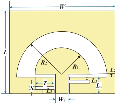
The structure of the proposed monopole wearable antenna is shown in Fig. 1. The simple structure and planar characteristic of the antenna make it easy to be conformal with human body. The antenna is fed by a Coplanar Waveguide (CPW), and the feeding unit is a semi-circular metal patch with radius R1. Both the feeding unit and radiation patch are printed on the upper layer of the dielectric substrate which offer a single-layer fabrication process. In order to cover 2.45 GHz band of ISM, the impedance bandwidth of the antenna is expanded by combining the circular slot with the asymmetric slots. The
L
W1
L1
S T
R1 R2
L3
L3 L2
antenna is printed on polyimide material with flexible characteristics (εr = 3.5, tanδ = 0.002). The antenna structure is adjusted by ANSYS HFSS based on finite element method to optimize the antenna performance.
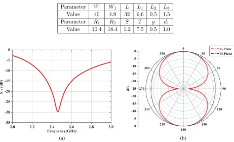
As shown in Fig. 2(a), the antenna covers 2.27∼2.76 GHz of ISM band and has good impedance matching characteristics at 2.45 GHz, withS11 of−29.85 dB. Fig. 2(b) shows theE-plane and H-plane radiation patterns of the antenna. It can be seen that the radiation direction of the monopole antenna is omnidirectional. The radiation of the back lobe, that is, the radiation energy of the antenna to the human body is the same as that of the forward radiation. The overall size of the designed antenna is 40 mm×32 mm×1 mm, with a simple structure. The specific dimensions of the parameters of each part of the proposed antenna are shown in Table 1.
Table 1. Dimensions of the proposed antenna in mm.
Parameter W W1 L L1 L2 L3
Value 40 4.9 32 6.6 0.5 1.5
Parameter R1 R2 S T g d1
Value 10.4 18.4 1.2 7.5 0.5 1.0
2.0 2.2 2.4 2.6 2.8 3.0
-35 -30 -25 -20 -15 -10 -5 0
S
11
(dB)
Frequency(GHz)
-25 -20 -15 -10 -5
0 0
30
60
90
120
150 180
210 240 270
300 330
-25
-20
-15
-10
-5
0
E-Plane H-Plane
dB
(a) (b)
Figure 2. Simulated results of the monopole antenna. (a) Simulated S11 of the monopole antenna alone in free space. (b) Simulated E-plane andH-plane normalized radiation patterns of the monopole antenna at 2.45 GHz.
In order to study the effects of electromagnetic radiation on human body, Fig. 3 shows the relationship between SAR and tissue depthdwhen the antenna is placed on the human surface. In the range of 0∼17 mm tissue depth, the SAR values are generally higher than the standard of 1.6 W/kg SAR maximum of 1 g tissue in 6 minutes defined by IEEE. From the radiation pattern and SAR value, it can be seen that the proposed antenna may have some impact on human health and cannot meet the practical application requirements of wearable antenna. Moreover, the antenna needs to be placed on human body in application, and the electrical characteristics of human tissue may change the impedance matching of antenna. Based on these, the antenna needs to be further improved.
2.2. Design of L-Shaped Slot Artificial Magnetic Conductor Structure
0 5 10 15 20 0
4 8 12 16 20
SAR (W/kg)
Depth (mm)
Local SAR Average SAR
Figure 3. SAR of the proposed antenna placing on human tissue model.
structure with the same-phase reflection characteristics of±90◦ is designed to improve the back lobe of the antenna and the forward gain, also reduce the the influence of impedance mismatch caused by human tissue characteristics. Distinguished from other structures, the important effects of AMC structure in reducing the height of the antenna profile and the coupling between antenna and human body, make it suitable for improving the performance of wearable antenna.
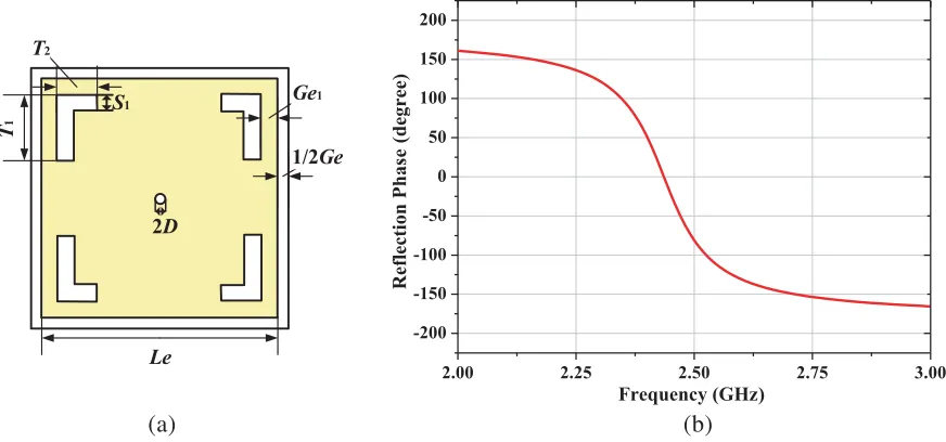
Based on the structure of classical Mushroom-AMC, a new type of AMC unit is designed. The AMC unit structure is shown in Fig. 4(a), and the dielectric substrate is copper-clad on both sides of a flexible polyimide material with a thickness of 1.5 mm. The central position is a metallized through hole, connecting the upper and lower layers. L-shaped grooves around the rectangular radiation patch are to realize the miniaturization of AMC unit. The reflective phase of the L-slot AMC cell structure is simulated as shown in Fig. 4(b). The reflective phase band gap of ±90◦ covers 2.4 ∼2.485 GHz in the ISM band, and the reflective phase point of 0◦ operates at 2.45 GHz. By optimizing the parameters, the cell has a size of 28.9 mm×28.9 mm×1.5 mm. The specific parameters of AMC unit cell are shown in Table 2.
S1
2D
1/2Ge
Ge1
Le
T
1
T2
2.00 2.25 2.50 2.75 3.00
-200 -150 -100 -50 0 50 100 150 200
Reflection Phas
e
(
degree
)
Frequency (GHz)
(a) (b)
Table 2. Dimensions of the proposed AMC structure in mm.
Parameter Le Ge Ge1 S1 T1 T2 D d1
Value 28.9 1 2 2 8 5 1 1.5
2.3. Wearable Antenna System Loaded with L-Slot AMC Structure
In Sections 1.1 and 1.2, the single-frequency flexible monopole antenna and L-slot AMC cell applied to ISM 2.45 GHz band are proposed, as well, and the basic performance is analyzed. In this section, the proposed AMC cell is periodically arranged and loaded on the monopole antenna, and the back lobe radiation of the antenna is reduced by using ±90◦ reflection characteristic, thus the coupling between the antenna and the human body is reduced. Through the simulation and optimization of the wearable antenna system, the antenna system is finally made up of 2×2 AMC structure. As shown in Fig. 5, in order to realize a good impedance matching of the antenna system, the plastic foam isolation is placed between the monopole antenna and the AMC structure, and the distance is adjusted by 2.5 mm. The size of the whole antenna system is 66.8mm×66.8 mm.
d1 d2
d3
Foam
Figure 5. Structure of the proposed wearable antenna.
Figure 6 shows the simulation results of the antenna integrated with AMC structure. In Fig. 6(a), it is indicated that the antenna system operates at 2.45 GHz in the ISM medical band, andS11 reaches −15.12 dB. Because the±90◦ reflection phase band gap of the artificial magnetic conductor structure is relatively narrow, the operating bandwidth of the system antenna becomes narrower after integrating the AMC structure, but it can still cover most of the ISM medical frequency bands. The E-plane and H-plane radiation patterns of the antenna system are shown in Fig. 6(b), and obviously, the back lobe of the antenna is improved. It can be concluded that the proposed AMC structure can effectively reduce the electromagnetic radiation of the monopole antenna to the human body, and the forward gain of the antenna is much higher than that of the antenna without AMC structure, achieving the gain of 7.47 dBi.
3. ANALYSIS OF ANTENNA STABILITY PERFORMANCE 3.1. Performance Analysis of Antenna Near Human Body
2.00 2.25 2.50 2.75 3.00 -20
-15 -10 -5 0
S
11
(dB)
Frequency (GHz)
-40 -30 -20 -10 0 10
0
30
60
90
120
150 180
210 240 270
300 330
-40
-30
-20
-10
0
10
E-Plane
H-Plane
dB
(a) (b)
Figure 6. Simulated results of the wearable antenna with AMC reflector. (a) Simulated S11 of the integrated antenna alone in free space. (b) Simulated E-plane and H-plane normalized radiation patterns of the integrated antenna at 2.45 GHz.
not have a negative influence on human health at work, the performance of the antenna placed on the human body should be analyzed to demonstrate whether it meets the practical application requirements or not. Fig. 7 simulates the basic model of human tissues, consisting of skin, fat, and muscle with the size of 130 mm×120 mm×13 mm. The electrical properties of each layer are shown in Table 3 [15]. The antenna is placed at a height of 0 mm from the tissue surface.
Skin
Fat
Muscle 1mm
2mm
10mm
130mm
13
m
m
antenna
Figure 7. Human body tissue model.
Table 3. Electrical properties of human tissues.
Skin Fat Muscle
εr 38.0067 10.8205 55
tanδ 0.0255 0.0047 0.04
2.00 2.25 2.50 2.75 3.00 -20
-15 -10 -5 0
S
11
(dB)
Frequency (GHz)
On body With AMC
1.50 1.75 2.00 2.25 2.50 2.75 3.00
0 5 10 15 20 25 30 35 40
Front to Back Rati
o
Frequency (GHz) Without AMC With AMC On body
(a) (b)
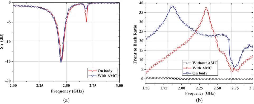
Figure 8. System simulated results of the integrated antenna with human body tissue model. (a) Simulated S11of the integrated antenna in free space and on body. (b) Front-to-back ratio ratio of the integrated antenna.
The simulation results of the system loaded with human tissues are shown in Fig. 8. Compared with the simulation results without human tissues, Fig. 8(a) shows thatS11of the antenna has a slight deviation, while the overall performance of the antenna is basically same as the original antenna. It can be seen that the designed wearable antenna is less affected by the electrical characteristics of human tissues, and its performance is relatively stable. In a wearable antenna, a larger front-to-back ratio of the antenna will achieve a smaller antenna radiation back to the human body, and the antenna has higher security. Fig. 8(b) is a comparison of the antenna without AMC structure, antenna with AMC structure, and antenna system with human tissues. It can be seen from Fig. 8(b) that the antenna’s front-to-back ratio is approximately 1 without any other structures. That is to say, the proposed monopole antenna has the same forward and backward radiations, which cannot meet the practical application requirements. On this basis, when the proposed AMC structure is loaded on the antenna, the front-to-back ratio is obviously improved, much larger than 20 dB, in the ISM 2.4∼2.485 GHz band. This indicates that due to the addition of an AMC structure, the antenna’s back radiating wave scatters along the edge of the antenna to the human tissues surface, and some of these waves are absorbed by the human body, while most of them are reflected. Therefore, the antenna’s front-to-back ratio of the loaded AMC structure is improved. Also, compared with antennas in free space, the antenna’s front-to-back ratio is much higher. The above data comparison demonstrates that the antenna electromagnetic radiation to human body will be greatly reduced. The antenna’s front-to-back ratio changes slightly when being placed on the human tissues compared with the antenna in free space. In the ISM band, the front-to-back ratio is still greater than 20 dB, which shows that the proposed wearable antenna meets the practical application requirements.
0 2 4 6 8 10 12 14 0.00
0.02 0.04 0.06 0.08 0.10 0.12
SAR (W/kg
)
Depth (mm)
Local SAR Average SAR
Figure 9. SAR of the proposed antenna system placing on human body tissue model.
3.2. Analysis of Antenna Bending Performance
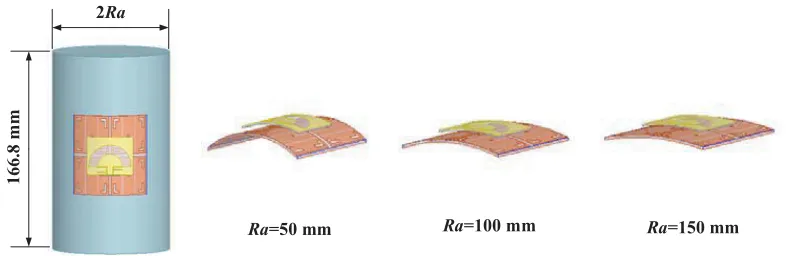
When a wearable antenna works on the human surface, it needs to be integrated with clothing to conform to the human body. Because the human body parts, such as arms and legs, have a certain radian, and when the human body is doing some sports, the antenna is prone to bending deformation. In order to verify that the proposed antenna still maintains a good performance, when it is deformed, the bending performance of the antenna is analyzed in this section. Fig. 10 shows the antenna bent on the surface of a cylinder with different radii Ra. The smaller the radius of the cylinder is, the greater the bending deformation of the antenna is.
2Ra
166.8
m
m
Ra=50 mm Ra=100 mm Ra=150 mm
Figure 10. The integrated antenna with different bending degrees.
The simulation S11 curves of the antenna under different bending degrees are shown in Fig. 11. It can be seen that under different deformation degrees, S11 are all less than −10 dB, and when the Ra value becomes smaller, the corresponding antenna operating frequency shifts to high frequency, but the operating frequency is still in the ISM. The analysis proves that the proposed antenna has a stable performance in the case of bending, satisfying the requirements of practical application.
4. FABRICATION
2.0 2.2 2.4 2.6 2.8 3.0 -25
-20 -15 -10 -5 0
S
11
(dB)
Frequency (GHz)
Ra=50mm Ra=100mm Ra=150mm
Figure 11. Comparison of S11 of the integrated antenna with different bending degrees.
Figure 12. The top view of the fabricated antenna.
(a) (b)
Figure 13. (a) Measured photograph of the fabricated antenna in free space. (b) Measured photograph of the fabricated antenna placed on the part of the human body.
2.0 2.2 2.4 2.6 2.8 3.0
-18 -15 -12 -9 -6 -3 0
S
11
(dB)
Frequency (GHz)
Simulated Measured On body
Figure 14. Simulated and measured S11 comparison of the integrated antenna.
operating frequency of the measurement is slightly shifted to the right, at 2.45 GHz, and S11 reaches −13.62 dB, which meets the design requirements.
The antenna is placed in a microwave anechoic chamber to test the far-field radiation pattern, and the test environment is shown in Fig. 15. The test comparison of the simulated and measured normalized direction diagrams of xoz and yoz planes are shown in Fig. 16. The radiation pattern of the wearable antenna without AMC structure is no longer 8-shaped onxoz plane. To a certain extent, the back lobe is reduced. However, compared with the simulation results, there are some deviations. The analysis deviations may result from the change of the distance between the upper antenna and the AMC reflector during the test, causing a uncontrollable distance, and the welding of antenna feeding port and field test environment may also have some impact on the actual test of antenna.
-40 -30 -20 -10 0 0 30 60 90 120 150 180 210 240 270 300 330 -40 -30 -20 -10 0 dB Simulated Measured -40 -30 -20 -10 0 0 30 60 90 120 150 180 210 240 270 300 330 -40 -30 -20 -10 0 dB Simulated Measured (a) (b)
Figure 16. Simulated and measured (a)E-plane and (b)H-plane normalized radiation patterns of the integrated antenna at 2.45 GHz.
5. CONCLUSION
A wearable antenna with an L-slot AMC structure for ISM application is proposed and demonstrated in this paper. With the addition of an AMC structure, the radiation of the antenna back lobe is effectively reduced, improving the performance of the antenna. In ISM medical band, the antenna’s front-to-back ratio is greater than 20 dB, achieving a gain of 7.47 dBi. The human tissue model loaded by the wearable antenna is systematically analyzed. The SAR value is less than 0.15 W/kg, which is far less than the international application standard, proving that it will not cause harm to human health. Also, the antenna still has stable performance under the bending conditions. On the basis of simulation, the antenna is fabricated and tested. The realized antenna has a strong agreement with the simulation results. Therefore, these demonstrated properties of the proposed antenna ensure it as an ideal choice for wearable devices such as medical monitoring and medical sensing in WBAN.
ACKNOWLEDGMENT
REFERENCES
1. Astrin, A. W., H. B. Li, and R. Kohno, “Standardization for body area networks,” IEICE Transactions Communications, Vol. E92-B, No. 2, 366–372, 2009.
2. Li, M., W. Lou, and K. Ren, “Data security and privacy in wireless body area networks,” IEEE Wireless Communications, Vol. 17, No. 1, 51–58, 2010.
3. Karaoguz, J., “High-rate wireless personal area networks,” IEEE Communications Magazine, Vol. 39, No. 12, 96–102, 2001.
4. Declercq, F., H. Rogier, and C. Hertleer, “Permittivity and loss tangent characterization for garment antennas based on a new matrix-pencil two-line method,”IEEE Transactions on Antennas and Propagation, Vol. 56, No. 8, 2548–2554, 2008.
5. Samal, P. B., J. S. Ping, and G. A. E. Vandenbosch, “UWB all-textile antenna with full ground plane for off-body WBAN communications,” IEEE Transactions on Antennas and Propagation, Vol. 62, No. 1, 102–108, 2014.
6. Yan, S., P. J. Soh, and A. E. V. Guy, “Wearable dual-band magneto-electric dipole antenna for WBAN/WLAN applications,” IEEE Transactions on Antennas and Propagation, Vol. 63, No. 9, 4165–4169, 2015.
7. Simorangkir, R. B. V. B., A. Kiourti, and K. Esselle, “UWB wearable antenna with full ground plane based on PDMS-embedded conductive fabric,” IEEE Antennas and Wireless Propagation Letters, Vol. 17, No. 3, 493–496, 2018.
8. Agarwal, K., Y. X. Guo, and B. Salam, “Wearable AMC backed near-endfire antenna for on-body communications on latex substrate,” IEEE Transactions on Components Packaging and Manufacturing Technology, Vol. 6, No. 3, 346–358, 2017.
9. Gaetano, D., P. McEvoy, M. J. Ammann, et al., “Footwear antennas for body area telemetry,” IEEE Transactions on Antennas and Propagation, Vol. 61, No. 10, 4908–4916, 2013.
10. Kwak, S. I., D. U. Sim, J. H. Kwon, et al., “Design of PIFA with metamaterials for body-SAR reduction in wearable applications,”IEEE Transactions on Electromagnetic Compatibility, Vol. 59, No. 1, 297–300, 2017.
11. Jiang, Z. H., D. E. Brocker, P. E. Sieber, et al., “A compact, low-profile metasurface-enabled antenna for wearable medical body-area network devices,” IEEE Transactions on Antennas and Propagation, Vol. 62, No. 8, 4021–4030, 2014.
12. Raad, H. R., A. I. Abbosh, H. M. Al-Rizzo, et al., “Flexible and compact AMC based antenna for telemedicine applications,” IEEE Transactions on Antennas and Propagation, Vol. 61, No. 2, 524–531, 2013.
13. Ashyap, A. Y. I., Z. Z. Abidin, S. H. Dahlan, et al., “Robust low-profile electromagnetic band-gap-based on textile wearable antennas for medical application,” International Workshop on Antenna Technology: Small Antennas, Innovative Structures, and Applications, 158–161, IEEE, 2017. 14. Di, Y. H., X. Y. Liu, and M. M. Tentzeris, “A conformable dual-band antenna equipped with AMC
for WBAN applications,” Antennas & Propagation, 388–391, IEEE, 2014.