FACTORS AFFECTING THE PERFORMANCE OF THE RADAR ABSORBANT TEXTILE MATERIALS OF
DIFFERENT TYPES AND STRUCTURES A. A. Hebeish
National Research Center Dokki, Giza, Egypt
M. A. Elgamel Faculty of Applied Arts Helwan University Dokki, Giza, Egypt
R. A. Abdelhady Textile Department Faculty of Applied Arts Helwan University Giza, Egypt
A. A. Abdelaziz Faculty of Engineering
Misr International University (MIU) Cairo, Egypt
with lossy material. For coating, several formulas of fabrics using carbon black were tested to determine the best chemical treatment in accordance with their functional performance. Lab measurements have been done to get optimum formulas and optimum fabrics structures for high radar absorption performance.
1. INTRODUCTION
Over the past few years, there has been an emphasis on reducing the radar cross section (RCS) of military weapons using different techniques [1–6]. These techniques can now be applied to the civilian market to solve many problems. The most common and simple structure to reduce the level of the reflected power from a metallic surface is the single layer structure known as Salisbury screen [7–10] which is a sheet of porous material (resistive sheet) impregnated with graphite and spaced a quarter-wavelength of a metallic backing plate. This resistive sheet can also be used as an interference suppression with microstrip planar antennas [11, 12] when a half-wavelength spacer is used. Exploring the most suitable resistive sheet in terms of uniformity and resistivity is a particularly important issue [13, 14]. Fabric parameters, properties, structures and chemical materials have been considered to achieve our goal.
2. RADAR ABSORBING TECHNIQUES
screen type absorber can be improved by constructing a multi-screen absorber, one behind the other and separated by a dielectric spacer. In this paper, the interest is to reduce the RCS using Salisbury screen technique as a radar absorbing materials.
3. SALISBURY SCREEN AS A RADAR ABSORBER MECHANISM
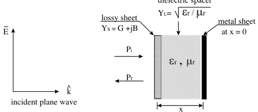
The Salisbury screen is a resonant absorber created by placing a lossy sheet on a low dielectric constant spacer in front of a metal plate forming one layer structure. Calculation of the reflected power of a normally incident plane wave from an infinite flat one-layer structure is a straight forward problem involving application of boundary conditions derived from Maxwell’s equations to the general solution for the electric and magnetic fields in that layer. The basic structure, shown in Figure 2, consists of only one dielectric layer covered with a lossy sheet and stacked against a metallic backing plate with the following parameters:
Dielectric parameters of the spacer, normalized to free space, is equal toεr =µr= 1
Layer intrinsic admittanceYL, normalized toY0, is given by: YL=
εr µr
whereY0 is the free space admittance equal to 1/377 Ω
Sheet admittanceYs, normalized to Y0, is given by: Ys=G+J B
The reflected power, in dB, of a normally incident plane wave is given by:
|R|= 20 log10Pr Pi
(1)
where Pi, Pr are the amplitudes of the incident and reflected
propagated waves and equal to [1]:
Pi =
e−jk0x 2
[2 + (G+jB)]ejk0x−(G+jB)e−jk0x
Pr=
ejk0x 2
−(G+jB)ejk0x−
2−(G+jB)e−jk0x
(2)
wherek0 is the free space wave number and is equal to 2π/λ.
From Equations (1) and (2), and assuming that the lossy sheet is an infinitesimally thin resistive sheet of conductanceG (i.e.,Ys=G),
then the reflected power Pr will be zero if:
−Gjk0x−(2−G)e−jk0x
This requires that the magnitudes of the two exponential in Equation (3) be equal and their phase angles be opposite. The equal amplitude requirement forces the normalized conductanceGto be one, then:
Pr=−ejk0x
ejk0x+e−jk0x
2 =−e
−jk0xcos2πx
λ (4)
So, the condition forPr to be zero is given by:
x= λ 4 +n
λ
2, n= 0,1,2, . . . . (5)
Thus for zero reflectivity, a Salisbury screen requires a 377 ohm per square sheet resistance (G = 1) set at a quarter wave length in front of a perfectly reflective backing. The resistive sheet can either be uniform in such as carbon weave, cloth or paper, or constructed from circuit analogue structure pattern printed with lossy wires or crosses or square metal, or pure metal plus a lossy sheet. In our research, we will concentrate on uniform resistive sheet of different structures of textile fabrics coated with carbon black with several formulas.
4. EFFECT OF TEXTILE FABRIC STRUCTURE ON ELECTROMAGNETIC WAVE PROPERTIES
The fabric structure used is highly affected by the produced fabric specification. As long as the structure of the fabric is balanced, the results obtained in both direction, (the weft and the warp direction) become more closer. Woven Fabrics with plain structure are almost homogenous because the number and the count of the used yarn are almost balanced. Hence the cover factor of the wrap and weft is balancedk1=k2 and this brings about same percentage of appearance
the surface of the fabrics owing to the arrangement of the needles in the dail and cylinder. Thus the fabric performance is improved in the vertical direction than on the horizontal which is the direction of the textile.
5. PARAMETERS AFFECTING RESISTIVE SHEET MANUFACTURE
Carbon black is the main pigment material used for chemical treatment of all fabric samples under test. As pigment dyes, carbon black material just sticks on the fabric surface or penetrate on the “haired surface” fibers of the fabric samples. So, on this basis, the relationship between woven fabric construction parameters and desirable resistivity could be limited on the ability of fabric surface to “hold” the carbon black, more than knitted ones, either weft or wrap knitted. This can be interpreted by the intersection density, as weave number (M =ni/nr),
where the (ni) number of intersection per inch, and (nr) number of
Figure 1. Effect of carbon concentration on the resistivity value obtained from plain woven fabric.
lossy sheet metal sheet
Ys = G +jB
Pi
Pr
dielectric spacer
YL=
x incident plane wave
k ^
E at x = 0
Figure 2. Configuration of Salisbury screen as single layer absorbing mechanism.
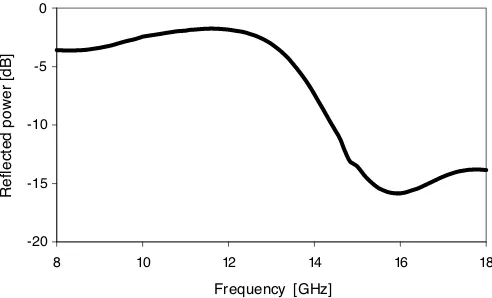
configuration shown in Figure 2 at spacing x = 4.7 mm, has been measured using PR-17 microwave reflectometer to assist the resistive sheet absorption. The basic measurement technique is a bistatic RF return loss test much like the NRL arch [1]. The reflectometer operates in free space using transmitting and receiving antennas oriented at a bistatic angle of±15 degree. Figure 3 shows the measured absorption of the tested sample. A minimum reflective power equal to
−15.84 dB at 16 GHz for a low dielectric spacer (εr=µr= 1) while the
performance is still respectable at frequency band 15–17 GHz.
-20 -15 -10 -5 0
8 10 12 14 1 8
Frequency [GHz]
Reflected power [dB]
6 1
Figure 3. Measured reflected power in dB from the absorbing mechanism shown in Figure 2 atx= 4.7 mm.
7. CONCLUSION
Current research work is concerned with investigation of radar absorbing mechanism. Emphasis is placed on the single layer structure mechanism of a resistive sheet with different fabric structures. The latter were coated using different formulations based on carbon black. Results obtained by varying the fabric structure and those obtained by changing the ingredients of the carbon black-based formulation, brings into focus the most appropriate conditions for obtaining textiles with high ability of camouflage.
REFERENCES
2. Zhao, S. C., B. Z. Wang, and Q. Q. He, “Broadband radar cross section reduction of a rectangular patch antenna,” Progress In Electromagnetics Research, PIER 79, 263–275, 2008.
3. Abdelaziz, A. A., “Improving the performance of an antenna array by using radar absorbing cover,” Progress In Electromagnetics Research Letters, Vol. 1, 129–138, 2008.
4. Lagarkov, A. N., V. N. Kisel, and V. N. Semenenko, “Wide angle absorption by the use of a meta-material plate,” Progress In Electromagnetics Research Letters, Vol. 1, 35–44, 2008.
5. Kusayakin, O. P., P. N. Melezhik, A. Y. Poyedinchuk, and O. S. Troschylo, “Absorbing properties of a negative permittivity layer placed on a reflecting grating,”Progress In Electromagnetics Research, PIER 64, 135–148, 2006.
6. Xu, Z., W. Lin, and L. Kong, “Controllable absorbing structure of meta-material at microwave,” Progress In Electromagnetics Research, PIER 69, 117–125, 2007.
7. Salisbury, W. W., “Absorbed body of electronic waves,” U.S. Patent No. 2, 599, 944, June 10, 1952.
8. Lederer, P. G., “Modeling of practical Salisbury screen absorbers,” IEE Colloquium on Low Profile Absorbers, Digest No. 1992/129. 9. Abdelaziz, A. A., “A novel technique for improving the
performance of salisbury screen,” Progress In Electromagnetics Research Letters, Vol. 1, 1–8, 2008.
10. Gustafsson, M., “RCS reduction of integrated antenna arrays with resistive sheets,” Journal of Electromagnetic Waves and Applications, Vol. 20, No. 1, 27–40, 2006.
11. Abdelaziz, A. A., A. Henderson, and J. R. James, “Microstrip planar array with interference suppression radome,” Electronics Letters, Vol. 28, No. 15, 1993.
12. Henderson, A., A. A. Abdelaziz, and J. R. James, “Investigation of interference suppression radome for microstrip arrays,”Proceeding ICAP, Edinburgh, 1993.
13. Pourova, M. and J. Vrba, “Analytical solutions to the applicators for microwave textile drying by means of zigzag method,”PIERS Online, Vol. 3, No. 8, 1204–1207, 2007.