Experimental Verification of a Compact Zeroth Order Metamaterial
Substrate Integrated Waveguide Antenna
Walaa Wahba1, Mahmoud A. Abdalla1, *, and A. M. M. Allam2
Abstract—This paper presents a zeroth order metamaterial substrate integrated waveguide antenna. The antenna is designed to have a compact size based on employing only one composite right/left-handed cell. The antenna resonates at 6.1 GHz with overall radiator size of 14.4 mm×8 mm which represents 50% size reduction compared to conventional microstrip patch antenna that operates at the same frequency. The zeroth order mode of the antenna has been verified using analytical explanation and full wave simulations. Moreover, the full wave simulations and experimental measurements have been employed to confirm the antenna matching properties and radiation characteristics.
1. INTRODUCTION
The increasing demands in wireless communication require the development of antenna designs and configurations. One of the interesting novel antenna designs was based on employing metamaterials due to their unique features associated with electromagnetic waves propagation. Left-handed metamaterials (LHMs), which can exhibit simultaneous negative permittivity and permeability, have been realized in planar form by loading a transmission line (TL) with series capacitors and shunt inductors. Due to both parasitic inductance and capacitance of the TL, these structures can be treated as a negative refractive index TL [1] or composite right/left-handed (CRLH) TL [2]. CRLH TL has a nonlinear progressive propagation phase coefficient which can be negative, positive or zero. Based on this unique property, many ultra-compact antennas [3–5] have been introduced. One of the novel properties of the CRLH TL is its zeroth order mode which enables the design of ultra-compact microwave devices. Examples for these components include resonators [6], filters [7], phase shifter [8] and antennas [9–13].
On the other hand, the Substrate Integrated Waveguide (SIW) was suggested for designing a high performance microwave and millimeter wave components. They introduce a trade-off between the low loss of waveguide and low cost of planar transmission lines. Recently, a CRLH SIW structure was introduced for the first time in [14]. The CRLH SIW structure was based on the similarity between equivalent circuits of CRLH TL and SIW except the series capacitance in CRLH TL that can be added on the top plane of an SIW structure. Different realizations of CRLH SIW TL were reported by Dong and Itoh for low microwave band [14] and by Okubo et al. [15] for high microwave bands. CRLH SIW TL has been employed in many microwave components such as filters [16], triplexer [17], coupler [18], phase shifter [19] and impedance transformer [20]. A big deal of research on CRLH SIW was devoted into antennas. This starts with forward/backward leaky wave antennas [21] and then resonant antennas [22–27].
In this paper, we introduce a compact zeroth order mode resonant CRLH SIW antenna. The theoretical design procedures are discussed. The antenna performance is investigated using the electromagnetic full wave simulations and measurements with good agreements between results.
Received 29 May 2016, Accepted 19 September 2016, Scheduled 29 September 2016
* Corresponding author: Mahmoud Abdelrahman Abdalla (maaabdalla@ieee.org).
2. ZEROTH ORDER CRLH SIW ANTENNA ANALYSIS
The proposed antenna has been designed using only one cell of CRLH SIW TL. The CRLH SIW antenna is designed to operate at 6.1 GHz. The antenna is fed by a microstrip line as shown in Fig. 1(a). The CRLH SIW unit cell equivalent circuit model is shown in Fig. 1(b). The elements (LR and CR) are the parasitic inductance and capacitance, respectively, whereas the elements (LL and CL) represent the loading inductance and capacitance, respectively. The capacitor (CL) is realized using interdigital capacitor (IDC) etched on the top surface of SIW. The inductor (LL) is realized as a series of metallic via holes. The employed substrate is Rogers 5880 with dielectric constant = 2.2 and thickness = 0.508 mm. The relation between SIW structure and CRLH transmission line has been analysed in details in [28].
(a) (b)
Figure 1. (a) The 2D structure of a microstrip fed CRLH SIW transmission line, (W1 = 0.51 mm, W2 = 0.35 mm, Lf = 3 mm, d = 0.95 mm, and S = 1.45 mm). (b) The equivalent circuit model of a CRLH SIW unit cell.
2.1. CRLH SIW Antenna Design Procedures
A block diagram for the antenna is shown in Fig. 2. The single band CRLH SIW antenna is designed as one CRLH SIW cell with open circuit termination. The design of the antenna has been started by designing a 50 Ω CRLH TL with zero phase at the operating frequency (6.1 GHz). This can be expressed as:
φCLRH =
jωLR+jωC1
L jωCR+ 1 jωLL
f=6.1e9
= 0. (1)
77/ZCLRH =
jωLR+ 1
jωCL
jωCR+ 1
jωLL
f=6.1e9
= 50 Ω. (2)
The interdigital capacitor and via inductor dimensions are calculated using formulas in [2, 29]. Given thathis the substrate thickness, lf the capacitor finger length, and all fingers spacing and width
= 0.2 mm, due to the fabrication limits, this is expressed as
CL(pF) = 3.937×10⁻⁵lf(εr+ 1) (0.11 (n−3) + 0.252), lfin [µm] (3)
LL = (μ0h) (4)
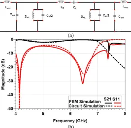
where μ0 is the free space permeability. Since elements CR and LR are patristic, they are adjusted to enclose physically the SIW CRLH unit cell and their final values obtained through final curve fitting stage. For modelling the transition from the SIW configuration to microstrip one, two inductors (Lext) and two capacitors (Cext) are added at the end of the CRLH cell as shown in Fig. 3(a). The circuit model in Fig. 3(a) is simulated using the commercial circuit simulator (advanced circuit simulator (ADS)). A comparison with the simulated circuit and full wave scattering parameter magnitudes for one unit cell is
(a)
(b)
Figure 3. (a) The equivalent circuit of a CRLH SIW unit cell with microstrip feeding. (b) A comparsion between the circuit/full wave scattering parameter magnitudes of the SIW CRLH unit cell.
shown in Fig. 3(b). The obtained values are CL= 2.2 pF and LL= 1.3 nH, CR= 1.3 pF, LR= 6.2 nH, Cext = 0.45 pF and Lext = 6.2 nH. It is clear that good agreement is achieved between the circuit and full wave simulations.
A confirmation of the zeroth order mode of the designed antenna has been done by comparing the phases of one, three and five CRLH SIW unit cells based on full wave simulations. The results are depicted in Fig. 4 where it is quite clear that the three cases have zero phase at 6.1 GHz, approximately. Below 6.1 GHz, the 5 cells have higher positive phase that confirms the LH passband, whereas above 6.1 GHz, the 5 cells have lower negative values which confirm the RH passband.
2.2. CRLH SIW Antenna Structure and Results
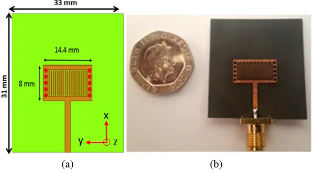
From pervious discussion, it has been concluded that by terminating the designed SIW unit cell with an open circuit termination, a zeroth order CRLH SIW antenna can be achieved at 6.1 GHz. Hence, as shown in Fig. 5(a), the proposed antenna has a total size = 33×31 mm2 (the employed cell is 14.4×8 mm2). The fabricated antenna prototype is shown in Fig. 5(b). It is worth to mention here that some changes have been carried out for the used cell in order to achieve good matching at the designed frequency. The main change is performed on the total size of the patch from (16.42 mm×13 mm) in the unit cell to (14.4 mm×8 mm) in the antenna. Also the number of fingers in interdigital capacitor has been changed from 15 fingers in the unit cell to 19 fingers in the antenna in addition to slight modifications on the length of fingers (Lf), spacing (W1 and W2), and spacing between vias (S) as depicted in Fig. 5. Finally, the proposed zeroth order CRLH SIW antenna has a smaller size with a reduction factor about 50% when it is compared with the conventional patch, and such patch has a size (19.2 mm×16.2 mm) at the same resonance (6.1 GHz) and over the same substrate.
(a) (b)
Figure 5. Prototype of the zeroth order CRLH SIW antenna, (a) antenna 2D layout (W1 = 0.3 mm, W2= 0.3 mm,Lf = 5.7 mm,d= 0.95 mm, and S= 1.45 mm), (b) fabricated antenna prototype.
Figure 6. The simulated and measured reflection coefficient of the zeroth order CRLH SIW antenna.
(a) (b)
Figure 7. Current distribution along (a) half wave patch antenna , (b) zeroth order CRLH SIW antenna.
3. ZEROTH ORDER CRLH SIW ANTENNA RADIATION CHARACTERISTICS
The simulated 3D radiation pattern at the resonant simulated frequency (6.1 GHz) is shown in Fig. 8. It is shown that the pattern is close to a typical broadside pattern. However, as a result of the antenna compactness, the gain of the antenna has a relatively small value (−4 dB) due to low efficiency of the antenna. For confirmation of the radiation properties, the simulated and measured normalized radiation patterns are compared to each other in Fig. 9. It has to say that since the antenna should work at resonant frequency, the radiation pattern comparison is done based on 6.1 GHz simulated pattern and 6.15 GHz measured pattern. It is clear that the measured pattern has a good agreement with the
(a) (b)
Figure 9. The measured and simulated normalized radiation pattern of the the proposed zeroth order CRLH SIW, (a) E-plane (XZ), (b)H-plane (Y Z).
Table 1. A comparison between proposed antenna and recent previous published work.
Reference Resonant
Frequency Substrate parameters
Physical Size (mm2)
Electrical Antenna size (in terms of free
space wavelength)
Antenna gain
This
Work 6.1 GHz
Rogers 5880,εr= 2.2,
Thickness = 0.508 mm 14.4×8 mm
2 0.4λ
o×0.2λo −4 dB
[30] 10 GHz FR4,εr= 4.4,
Thickness = 1.57 mm 14×14 mm
2 0.47λ
o×0.47λo 5.2 dB
[31] 10 GHz 12.5 GHz
RT/Duroid 5880,εr= 2.2,
Thickness = 1.575 mm 20×20 mm
2 0.66λo×0.66λo 0.83λo×0.83λo
2.933 dB 7.752 dB
[32] 13.4 GHz 17.9 GHz
RT/Duroid 5880,εr= 2.2,
Thickness = 1.575 mm 16.75×16.75 mm
2 0.75λo×0.75λo 1λo×1λo
NA
[33] 5.14 GHz RT/Duroid 5880,εr= 2.2,
Thickness = 1.575 mm 21×21.8 mm
2 0.36λ
o×0.37λo 6.08 dB
[34] 5.8 GHz RT/Duroid 5880,εr= 2.2,
Thickness = 1.27 mm 12×12.1 mm
2 0.232λ
o×0.234λo 1.55 dB
[35] 1.2 GHz 1.56 GHz
Rogers 5880,εr= 2.2,
Thickness = 1.508 mm 67.5×39.1 mm
2 0.27λo×0.156λo 0.351λo×0.203λo
3.77 dB 3.82 dB
[36] 3.67 GHz Rogers 5880,εr= 2.2,
Thickness = 1.575 mm 28.6×28.6 mm
2 0.35λ
simulated one in H-plane while some differences exist between two patterns inE-plane. These can be claimed due to some imperfect measurement conditions that can not be avoided. As an example for these imperfect conditions is the divergence of the measured radiation pattern at the end of the rotary antenna mast, i.e., near the angles±180◦. Another factor is some reflections near the antenna mounting on the mast, especially when measuring the radiation pattern in theE plane.
For completeness of our work, a comparison between the proposed antenna and some recent dual-band compact size antennas [30–36] is summarized in Table 1. It is worth to mention that the antenna size comparison is based on the radiator size. The comparison can tell that the antenna size is in a range (15%–50%) smaller than compared antennas. On the other hand, the antenna gain is lower than the larger antennas by amount (5 dB–8 dB). In other words, the comparison demonstrates that the ultra-size advantage of the proposed antenna is achieved at the expense of the small antenna gain and cost.
4. CONCLUSION
A compact zeroth order SIW CRLH antenna is introduced. The antenna is designed using only one CRLH SIW unit cell. The antenna size is only 33×31 mm2which represents 50% size reduction compared to conventional microstrip patch antennas. The antenna design and circuit modeling are discussed. The antenna performance parameters are extracted based on the electromagnetic full wave simulations. The radiation properties of the antenna have been confirmed using experimental measurements.
REFERENCES
1. Eleftheriades, G. V. and K. G. Balmain, Negative Refractive Metamaterials, John Wiley & Sons, New Jersey, 2005.
2. Caloz, C. and T. Itoh, Electromagnetic Metamaterials Transmission Line Theory and Microwave Applications, John Wiley & Sons, New Jersey, 2006.
3. Ziolkowski, R. W., P. Jin, and C. Lin, “Metamaterial-inspired engineering of antennas,” IEEE Proceedings, Vol. 99, No. 10, 1720–1731, 2011.
4. Dong, Y. and T. Itoh, “Metamaterial-based antennas,” IEEE Proceedings, Vol. 100, No. 7, 2271– 2285, 2012.
5. Lee, W. H., A. Gummalla, and M. Achour, “Small antennas based on CRLH structures: Concept, design, and applications,” IEEE Ant. and Prop. Mag., Vol. 53, No. 2, 10–25, 2011.
6. Abdalla, M. A. and Z. Hu, “Compact metamaterial coplanar waveguide ferrite tunable resonator,”
IET Microwaves, Antennas &Propagation, Vol. 10, No. 4, 406–412, 2016.
7. Abdalla, M., A. Y. Hassan, and A. M. Galal Eldin, “A compact high selective coupled gap CRLH TL based bandpass filter,”2015 9th International Congress on Advanced Electromagnetic Material in Microwave and Optics, 237–239, UK, Sep. 2015.
8. Abdalla, M. and Z. Hu, “Ferrite tunable metamaterial phase shifter,” 2010 IEEE AP-S International Antennas and Propagation Symposium Digest, 1–4, Toronto, Canada, Jul. 2010. 9. Wahba, W., M. Abdalla, A. Mohamed, and A. Allam, “A uni-planar microstrip CSRR metamaterial
antenna,” 2014 IEEE AP-S International Antennas and Propagation Symposium Digest, 545–546, Memphis, USA, 2014.
10. Abdalla, M. A., A. A. Ibrahim, and M. H. Abd El-Azeem, “Phase enhancement for multi-resonance compact metamaterial antennas,” Progress In Electromagnetic Research C, Vol. 60, 83–93, 2015. 11. Ibrahim, A. A. and M. A. Abdalla, “CRLH MIMO antenna with reversal configuration,”AE ¨U —
International Journal of Electronics and Communications, May 2016.
12. Abdalla, M. and F. Sadek, “Hybrid termination of metamaterial CRLH antennas,” 2015 IEEE AP-S International Antennas and Propagation Symposium Digest, 1188–1189, Vancouver, Canada, Jul. 2015.
14. Dong, Y. D. and T. Itoh, “Composite right/left-handed substrate integrated waveguide and half-mode substrate integrated waveguide,”IEEE MTT-S International Microwave Symposium Digest, 2009, MTT-S, 49–52, 2009.
15. Okubo, K., M. Kishihara, A. Yamamoto, J. Yamakita, and I. Ohta, “New composite right/left-handed transmission line using substrate integrated waveguide and metal-patches,” IEEE MTT-S International Microwave Symposium Digest, 2009, MTT-S, 41–44, 2009.
16. Yang, Q. and Y. Zhang, “Negative-order ridge substrate integrated waveguide coupled-resonator filter,” Electronics Letters, Vol. 50, No. 4, 290–291, 2014.
17. Chavez, A. C. and T. Itoh, “Novel miniaturized triplexer using substrate integrated technology,”
2010 Asia-Pacific Microwave Conference Proceedings (APMC), 678–681, 2010.
18. Sajin, G., A. C. Bunea, F. Craciunoiu, A. Dinescu, M. Zamfirescu, and R. Dabu, “CRLH mm-wave directional coupler on silicon substrate microprocessed by laser ablation,”2011 IEEE International Conference on Microwaves, Communications, Antennas and Electronics Systems (COMCAS), 1–4, 2011.
19. Ali, A., H. Aubert, N. Fonseca, and F. Coccetti, “Novel compact waveguide-based composite right/left-handed phase shifter with arbitrary phase shift and broad bandwidth: Analysis and design,” IEEE International Antennas and Propagation Symposium, 1–4, 2009.
20. Abdalla, M. A., W. Wahba, H. Elregaily, A. A. Allam, and A. Abdel Nazir, “A compact and wide band SIW metamaterial impedance transformer,” 2012 Middle East Conference on Antennas and Propagation (MECAP), 1–5, Egypt, 2012.
21. Dong, Y. and T. Itoh, “Composite right/left-handed substrate integrated waveguide and half mode substrate integrated waveguide leaky-wave structures,”IEEE Transactions on Antennas and Propagation, Vol. 59, No. 3, 767–775, 2011.
22. Dong, Y. and T. Itoh, “Miniaturized substrate integrated waveguide slot antennas based on negative order resonance,” IEEE Transactions on Antennas and Propagation, Vol. 58, No. 12, 3856–3864, 2010.
23. Ibrahim, W. W., M. A. Abdalla, A. M. M. Allam, A. A. Mohamed, and H. A. Elregeily, “A compact and dual band metamaterial substrate integrated waveguide antenna,” 2013 IEEE AP-S International Antennas and Propagation Symposium Digest, 966–967, USA, Jul. 2013.
24. Somarith, S., H. Kang, and S. Lim, “Frequency reconfigurable and miniaturized substrate integrated waveguide interdigital capacitor (SIW-IDC) antenna,”IEEE Transactions on Antennas and Propagation, Vol. 62, No. 3, 1039–1045, 2014.
25. Dong, Y. and T. Itoh, “Substrate integrated waveguide negative-order resonances and their applications,” IET Microwaves, Antennas& Propagation, Vol. 4, No. 8, 1081–1091, 2010.
26. Fang, S., T. Wang, Z. Liu, S. Zhu, and L. Yang, “Novel miniaturized BDS dual-band antenna based on composite right/left-handed substrate integrated waveguide,” 2014 Asia-Pacific Microwave Conference (APMC), 1399–1401, 2014.
27. Ibrahim, W., M. Abdalla, A. Allam, A. Mohamed, and H. Elregeily, “A compact and dual band metamaterial substrate integrated waveguide antenna,” 2013 IEEE AP-S International Antennas and Propagation Symposium Digest, 966–967, Orlando, USA, 2013.
28. Ibrahim, W., “Effect of metamaterials on antenna performance,” PhD Thesis, MTC College, Cairo, Egypt, 2015.
29. Yazdi, M. and N. Komjani, “Design of a band-notched UWB monopole antenna by means of an EBG structure,”IEEE Antennas and Wireless Propagation Letters, Vol. 10, 170–173, 2011. 30. Huang, J. Q., F. Qiu, C. Jiang, D. Lei, Z. Tang, M. Yao, and Q.-X. Chu, “Compact circularly
polarized SIW cavity-backed antenna based on slot SRR,”2015 Asia-Pacific Microwave Conference (APMC), Vol. 3, 1–3, 2015.
32. Lee, H., Y. Sung, C.-T. Wu, and T. Itoh, “Dual-band and polarization-flexible cavity antenna based on substrate integrated waveguide,” IEEE Antennas and Wireless Propagation Letters, Vol. 15, 488–491, 2016.
33. Sam, H., K. Somarith, and S. Lim, “Frequency reconfigurable and miniaturized substrate integrated waveguide interdigital capacitor (SIW-IDC) antenna,” IEEE Transactions on Antennas and Propagation, Vol. 62, No. 3, 1039–1045, 2014.
34. Yang, Q., X. Zhao, and Y. Zhang, “Miniaturized antenna based on series-inductance-flexible composite right/left-handed substrate integrated waveguide,” 2014 Loughborough IEEE Antennas and Propagation Conference (LAPC), 396–399, 2014.
35. Fang, S., T. Wang, Z. Liu, S. Zhu, and Y. Luo, “Novel miniaturized BDS dual-band antenna based on composite right/left-handed substrate integrated waveguide,” IEEE 2014 Asia-Pacific Microwave Conference (APMC), 1399–1401, 2014.