New Compact High Gain Radiating Element
for Base Station Antenna
Lo¨ıc Martin1, 2, *, Bruno Froppier1, Eduardo Motta Cruz1, and Tchanguiz Razban1
Abstract—Development of new network standards leads to the use of bulky base station antennas. Their wide surfaces are not compatible with integration constraints in urban areas. As the antenna is composed of a high number of radiating elements, reducing the surface of each element is a way to reduce the antenna surface. Compact radiating element would allow integration of several antennas on the initial surface. In this paper, a new compact antenna is designed in order to obtain up to four antennas at the place of one. The antenna gain and horizontal Half Power Beamwidth (HPBW) should be maintained. The size reduction is obtained by dielectric embedding. In order to determine the dielectric characteristics in which the antenna must be immersed, a theoretical model is proposed in this paper. Simulations and measurements are provided to show the evolution of the antenna’s performances in order to achieve manufacturer’s specifications.
1. INTRODUCTION
Nowadays, vertical linear antenna arrays (panel antennas) are used in mobile cellular telecommunication networks [1]. New antennas are required to satisfy 4G MIMO networks and future 5G Massive MIMO standard [2]. Moreover, several frequency bands are currently used by different standards such as GSM 900/1800, UMTS 900/2100 and LTE 800/1800/2600. This leads to the deployment of bulky and heavy multiband antennas [3]. In dense urban areas, the deployment of such kind of antennas with reduced visual impact is a technological challenge. Regarding the elementary antenna, a good solution is multiple stacked aperture coupled patch antenna [4, 5]. However, this structure remains complex for a mass production, and its bandwidth is generally limited to 30%. Another solution is to use the dipole antenna in all its forms for obvious reasons of simplicity and manufacturing costs [6, 7]. Its bandwidth can be better than 45%.
To perform multiple bands or for MIMO standard, operators multiply the antennas in the horizontal plane as presented in Fig. 1(a). Four single panel antennas are presented in Fig. 1(b) with Kathrein panel antennas resulting in an excessive surface. For a deployment in urban areas, the antenna surface has to be reduced. This may be done by reducing the number of radiating elements. In this case, the radiating elements must have higher directivity to keep constant the gain of the array. But, as a consequence, horizontal aperture of the array is reduced. So this way is not suitable. Another way is to reduce the surface of the radiating elements without reducing the inter element space (commonly around 0.8λ0, where λ0 is the free space wavelength) so that extra radiating elements can be added to the array to create new functions by creating subarrays as presented in Fig. 1(c).
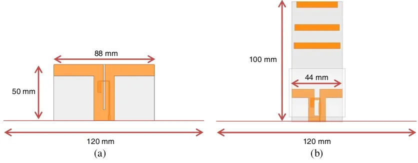
Classical dipoles occupy almost all the inter element space, see example in Fig. 2(a), for an antenna operating in the broadband from 1.7 to 2.7 GHz. This paper focuses on the design of a new high gain compact radiating element as presented in Fig. 2(b).
Received 12 April 2016, Accepted 27 June 2016, Scheduled 7 July 2016 * Corresponding author: Lo¨ıc Martin (loic.martin@univ-nantes.fr).
1 Universit´e Bretagne Loire, Universit´e de Nantes, UMR 6164, IETR Polytech Nantes, Rue Christian Pauc, BP50609, Nantes 44306,
(a) (b) (c)
Figure 1. Surface panel antenna reduction in 1.7–2.7 GHz band. (a) Four panel antennas (height = 1400 mm, width = 120 mm each). (b) Four panel antennas based on Kathrein antenna panels (height = 1400 mm, total width = 480 mm). (c) Principle of the new antenna array based on compact elements (height = 1400 mm, width = 120 mm).
(a) (b)
88 mm
120 mm 120 mm
100 mm
50 mm
44 mm
Figure 2. Example of a radiating element used in panel antennas. (a) Classical dipole element for 1.7–2.7 GHz broadband; (b) compact high gain antenna.
This paper is organized as follows: Section 2 describes the analysis of the new compact high gain antenna. Section 3 presents design and performances based on simulations. Realizations and measurements are presented in the Section 4. Conclusion is given in Section 5.
2. PRINCIPLE OF THE COMPACT ANTENNA
State of the art generally deals with size reduction of narrowband antennas or antennas with degradations on gain and bandwidth [8]. Two technologies are currently explored. Firstly, stacked high dielectric permittivity superstrates allow better gain, but they remain bulky and not suitable for low cost production [9]. Secondly, EBG (Electromagnetic Band Gap) technology does not provide sufficient bandwidth for mobile applications [10].
By encapsulating an antenna in a dielectric superstrate of relative permittivityεr, its size is reduced at constant resonant frequency. A model is developed below to design the compact antenna allowing the choice of thickness and dielectric superstrate permittivity. For an antenna surrounded by infinite and homogeneous superstrate of relative dielectric permittivityεr, antenna size is reduced proportionally to the wavelength:
Lr= √Lε0
r (1)
In the case of heterogeneous medium composed of air and dielectric superstrate, relative permittivity
εr must be replaced by an effective permittivity εeff. The Compression Factor is now defined by:
CF =√εeff = LL0
r (2)
Suppose a dipole antenna of length H surrounded by a dielectric of permittivity εr and thickness b as shown in Fig. 3(a). We propose Equation (3) to estimate its effective permittivity. In our equation, the effective permittivityεeff depends on relative permittivityεrand the superstrate thicknessbnormalized to the antenna size H and α a form factor. The effective permittivity varies from 1 (initial value) for
b= 0 toεr (final value) for btending to infinity.
(a) (b) (c) (d)
Figure 3. Antenna configurations (a) without and (b) with substrate. Configurations for effective permittivity at (c) initial εeff0 and (d) final εeff∞values.
Due to the realization constraints, the dipole is printed on a substrate of thicknesst(0.635 mm) as presented in Fig. 3(b). Its permittivityεs(2.55) is different from the dielectric superstrate permittivity. In this case the initial value isεeff0 instead of 1 and the final value isεeff∞ instead of εr. Equation (3) is modified to Equation (4).
εeff = 1 +
(εr−1)
1 +αH
b
(3)
εeff = εeff0+
(εeff∞−εeff0)
1 + αH
b
(4)
The initial and final values can be determined using Equation (3). For the initial value corresponding tob= 0 (Fig. 3(c) and Equation (5)), the model is defined by replacingεrbyεsandbbyt. For the final value corresponding tobtending to infinity, it is sufficient to replace in Equations (5) 1 byεr (Fig. 3(d) and Equation (6)).
εeff0 = 1 +
(εs−1)
1 +αH
t
(5)
εeff∞ = εr+
(εs−εr)
1 +αH
t
From Equations (4), (5) and (6), one obtainsεr versus band CF in Equation (7):
εr =
εeff0+
C2
F −εeff0
1 +αH
b −1 +εsαH t
1− 1
1 +αH
t
(7)
For a desired antenna length H and dielectric superstrate thickness b, first we calculate the value of
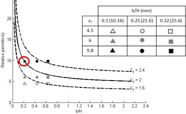
εeff0, then relative permittivityεr is obtained. Higher permittivity and/or thicker superstrate lead to a higherCF but with higher cost. Fig. 4 illustrates the evolution of the relative permittivity for different Compression FactorsCf. Manufacturers propose standard values for the permittivity and the thickness of dielectric materials. Some of them are indicated for Cf = 2 in Fig. 4.
Figure 4. Comparison of relative permittivity forCF from 1.6 to 2.4 (step 0.4) in function of b/H.
For a specific set of values (CF,H and εr), we can determine the dielectric superstrate thickness.
CF = 2 corresponding toεeff = 4 can be obtained forb/H = 0.22 andεr= 9.8. WithH = 44 mm, this leads tob/2 = 5.08 mm.
Electromagnetic (EM) simulation is used to validate the antenna model. Fig. 5 presents the model described with Ansys HFSS 15. Form factor α is tuned to fit the results of our model with EM simulations.
The dipole is printed on a substrate and placed between two layers of superstrates. This structure is placed in an air Box closed by Perfect Matching Layers Boundaries (PML). In this case, superstrates and substrate heights are considered as infinite. The resonant frequencies in the airf0 and in dielectric superstratefr are both determined when the imaginary part of the reflection coefficient is cancelled.
The antenna’s length is kept constant and the resonant frequency is tuned by the superstrate’s thickness. So, the effective permittivity is now defined by Equation (8).
εeff =
f0
fr 2
(8)
Figure 6 illustrates the behavior of εeff for different values ofb/H in the case of εr= 9.8.
A good matching between EM simulation and model is obtained withα = 0.8. It can be seen the effective permittivity starts at and ends at εeff0= 1.3 and ends at εeff∞= 6.
(a) (b)
Figure 5. Simulated configuration used for the antenna model. (a) 3D view; (b) side view.
ε eff= 4 b/H = 0.22
Figure 6. Effective permittivity for different ratios of Hb withεr= 9.8.
3. DESIGN OF THE HIGH GAIN COMPACT DIPOLE ANTENNA
Antenna design takes into account the specifications defined by the mobile operators, including sectorial aperture (around 70◦), gain (above 7 dBi) and a bandwidth greater than 45% (1.7–2.7 GHz). Considering dimensions of a conventional element of a panel antenna (88 mm length) a Compression Factor CF of 2 leads to a 44 mm dipole length. From Fig. 4, a dielectric superstrate from Rogers with relative permittivity of 9.8 and a thickness of 5.08 mm is chosen. The dipole is printed on a classic Diclad 527 from Arlon (εr = 2.55, t= 0.635 mm) embedded in the Rogers superstrate. The radiation is provided by the two arms of the dipole. The arms are dimensioned to resonate at the lowest frequencies. The feeder is constituted of a slot and a microstrip line ended by a λ4g open circuit stub, where λg is the guided wavelength. Slot’s width, line’s width and the stub are optimized to keep the Return Loss level lower than −10 dB all over the frequency band. The dipole gain without director is between 3 and 7.5 dBi in the band. Compact antenna cannot provide sufficient gain for this application. Antenna gain is increased by using directors. The theory used in this case is the same as for Yagi antenna [11]. The driven element length is generally slightly less than λ0
(a) (b)
100 mm
(c) (d)
Ground plane 40 mm
50 mm
44 mm
Figure 7. Presentation of the studied solutions of compact dipole antenna (a) without director, with (b) one, (c) two and (d) three directors added.
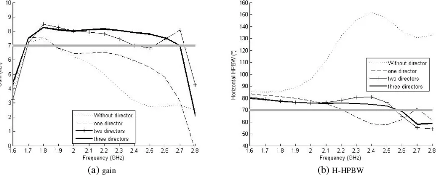
(a)gain (b)H-HPBW
Figure 8. Antenna simulation results with 0, 1, 2 and 3 directors in (a) gain and (b) horizontal HPBW.
for the dipole, is placed at λ0
4 from it. The director elements are smaller than the driven one and are close to 0.4λ0. Separation between them is between 0.3λ0 and 0.4λ0. The number of directors and their lengths are adjusted by simulation to obtain the specified gain. The four different antennas are presented by the Fig. 7.
Adding a first director increases the gain until 2.3 GHz. Adding a second director permits to obtain a gain close to 7 dBi for all the frequencies but the gain is not constant. The third director stabilizes the gain all over the band. The directors were optimized to provide the best gain in the entire band. All the directors’ lengths are different. The H-HPBW with (a) configuration is too large due to low gain. It decreases with the first director, as shown in (b) configuration. Fig. 8 presents the simulated performances obtained for gains and horizontal HPBWs. Each antenna is optimized by simulation to provide the best gain and the best horizontal HPBW over the frequency band.
The gain is higher than 7 dBi in the frequency band with (d) configuration. Adding directors above the compact dipole antenna decreases the horizontal HPBW slightly and stabilizes it around 70◦.
4. EXPERIMENTAL RESULTS AND DISCUSSION
From the above approach, a compact dipole antenna with three directors was fabricated with the materials specified in the previous section. Fig. 9 shows a view of the manufactured antenna placed on a ground plane of 12×12 cm2. The ground is made by brass.
We observe that the gain is higher than 7 dBi between 1.7 and 2.7 GHz due to the effect of the three directors above the dipole. The difference between the simulation and the measurement can be explained by the tolerances of the dielectric superstrate surrounding the antenna (permittivity and dimensions). The measured cross-polarization level is lower than−10 dB. The simulated and measured
Figure 9. Picture of the prototype compact elementary radiating antenna.
Figure 10. Comparison of simulated and measured gains. Dotted line: simulation; Continuous line: measurement.
(a)1.8 GHz (b)2.2 GHz (c)2.6 GHz
Figure 11. Simulated and measured radiation patterns in horizontal plane at (a) 1.8 GHz, (b) 2.2 GHz and (c) 2.6 GHz. Dotted line: simulation; Continuous line: measurement.
radiation patterns of the compact antenna are provided in Fig. 11 at 1.8, 2.2 and 2.6 GHz (respectively (a), (b) and (c)).
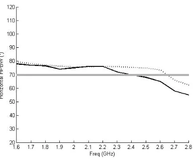
Simulations and measurements show good agreement for these three frequencies. The optimal horizontal HPBW for base station antennas is 70◦ over the band. Simulated and measured H-HPBW are illustrated in Fig. 12.
As expected, simulated and measured HPBW are slightly decreasing from 76◦ to 56◦ over the frequency band in measurement.
5. CONCLUSION
Massive MIMO and future 5G deployment require development of new compact wideband antennas. In order to get free surface inside the array, we proposed to reduce the elementary antenna dimensions. Size reduction is easily done by an embedded dipole antenna in a dielectric superstrate. A theoretical model was developed in order to design the new compact wideband dipole antenna. This one defines the characteristics of the dielectric for a specific compactness. We showed that immersing the antenna in a dielectric superstrate reduces the surface up to 75%. The theoretical model has been validated with EM simulations. Directors were added to control both gain and HPBW. Final performances are mostly close to a 7 dBi gain and close to 70◦ HPBW in horizontal plane. The new compact wideband antenna is well suited for new standard cellular communications, can be easily adapted for double polarization and opens a way to integrate several antennas in a given surface.
REFERENCES
1. Beckman, C. and B. Lindmark, “The evolution of base station antennas for mobile communications,” IEEE International Conference on Electromagnetics in Advanced Applications, 2007, ICEAA 2007, 85–92, 2007.
2. Larsson, E., O. Edfors, F. Tufvesson, and T. Marzetta, “Massive MIMO for next generation wireless systems,”IEEE Communications Magazine, Vol. 52, No. 2, 186–195, 2014.
3. Smith, M., D. Kitchener, and D. K. Power, “Multi-band cellular base station,” Antenna, Google Patents, 2001, https://google/patents/US6211841.
4. Lyou, M. and L. Bomson, “Compact size dual-polarized WLL base-station antenna using aperture coupled microstrip patches,”2000 International Symposium on Antennas and Propagation (ISAP), Vol. 4, 2200–2203, 2000.
5. Kwon, S., L. Bomson, and C. Jongin, “Compact size dual-polarized diversity microstrip antenna for IMT-2000 base-station,” 2001 International Symposium on Antennas and Propagation (ISAP), Vol. 2, 38–41, 2001.
6. Lee, J.-N., K.-C. Lee, and G.-D. Jo, “Design of the dual-polarized dipole antenna for small base station,”2012 International Symposium on Antennas and Propagation (ISAP), 1059–1062, 2012. 7. Liu, Y., H. Yi, F.-W. Wang, and S.-X. Gong, “A novel miniaturized broadband dual-polarized
dipole antenna for base station,” IEEE Antennas and Wireless Propagation Letters, Vol. 12, 2013. 8. Sanz-Izquierdo, B., J. C. Batchelor, R. J. Langley, and M. I. Sobhy, “Single and double layer planar multiband PIFAS,” IEEE Transactions on Antennas and Propagation, Vol. 54, No. 5, 1416–1422, May 2006.
9. Martin, L., E. Motta Cruz, B. Froppier, and T. Razban, “New heterogeneous superstrate high gain antenna,” 2015 9th European Conference on Antennas and Propagation (EuCAP), Lisbon, 2015. 10. Hajj, M., E. Rodes, D. Serhal, T. Mon´edi`ere, B. Jecko, and R. Chantalat, “Metallic EBG
superstrates for dual polarized sectoral base station antenna,” EuCAP 2009, 2859–2861, Berlin, 2009.