Design of Multilayer Microwave Absorbers Using Hybrid Binary
Lightning Search Algorithm and Simulated Annealing
Yuting Lu1 and Yongquan Zhou2, 3, *
Abstract—In this paper, a hybrid algorithm of binary lightning search algorithm and simulated annealing (BLSA-SA) is proposed to optimize the design of multilayer microwave absorbers for normal incidence. The multilayer absorber is designed to find a set of coatings that minimize the reflection coefficient over the desired frequency. The design problem is translated into solving the binary problem. Three different design examples are presented to verify the performance of the BLSA-SA. The results show that the reflection coefficient and thickness of BLSA-SA are better than those of other heuristic algorithms for multilayer absorber design. In the five-layer design, the standard deviation of BLSA-SA is the smallest among the 20 independent test results of the algorithms, which indicates that the BLSA-SA algorithm, has a strong stability.
1. INTRODUCTION
Microwave absorbers are often used to reduce radar echoes from anechoic chambers, aircraft, etc., as well as to achieve military self-concealing technology. Electronic instruments and equipment are usually coated or protected by absorbing materials to reduce the radar cross-section of various objects. Absorbent materials are made of ferrite, silicon carbide and other new absorption materials, attenuating incident electromagnetic radiation and converting its energy into heat. The goal of designing an absorber is to make these coatings not only suppress reflection over the desired frequency, but also need to be thin to be practical and economical [1]. Due to few electromagnetic parameters for adjustment, single layer absorbers have the drawbacks of narrow frequency band and thick structure. Recently, more and more researchers have focused on multilayer absorbers [2].
The absorption characteristics of multilayer microwave absorbers are related to the incident frequency, angle, electromagnetic parameters (permittivity and permeability) of materials, and the thickness and arrangement of each layer. In the case of a specific frequency range, how to choose materials and their thickness to minimize the reflection coefficient of the absorber can be considered as an optimization problem. In recent years, heuristic algorithms such as genetic algorithm (GA) [1–3], particle swarm optimization (PSO) [4–6], differential evolution (DE) [7, 8], and central force optimization (CFO) [9] have solved this problem. Although these algorithms optimize multilayer absorbers that minimize the reflection coefficient of the incident wave at multiple angles of incidence and in different frequency ranges, the thickness and reflection coefficient of the absorbers that they obtain can be further reduced. In this study, a hybrid method of binary lightning search algorithm and simulated annealing (BLSA-SA) is adopted to optimize the multilayer microwave absorber. The hybrid algorithm transforms the optimization problem of the absorber parameters into solving the binary problem, which obtains a more accurate solution. Among them, binary lightning search algorithm (BLSA) [10] is a binary
Received 3 June 2017, Accepted 4 August 2017, Scheduled 22 August 2017
* Corresponding author: Yongquan Zhou ([email protected]).
variable of the standard lightning search algorithm (LSA) [11], which is mainly used to solve binary problems directly, and has proved its search accuracy is high. Moreover, the purpose of introducing simulated annealing (SA) [12] is to avoid the BLSA falling into the local optimal solution. Before the introduction of simulated annealing, the crossover and mutation operations are added to make the algorithm have higher computational accuracy. The BLSA-SA algorithm is used to design absorbers that absorb the maximum amount of vertically incident microwave energy. The study is divided into three design examples, five-layer design, seven-layer design and three-layer design, and the frequency range is different. The BLSA-SA algorithm obtains thinner and less reflective absorbers than other heuristic algorithms for the three design examples. It is shown that BLSA-SA has a certain advantage in designing multilayer microwave absorber. The remainder of the paper is organized as follows.
This article is organized in the following sections. Section 2 briefly describes the physical model of the multilayer absorber. Section 3 presents the hybrid BLSA-SA algorithm. Section 4 is the experimental results and analysis, divided into three design examples. Finally, Section 5 gives conclusions and future studies.
2. PHYSICS MODEL OF MULTILAYER ABSORBER
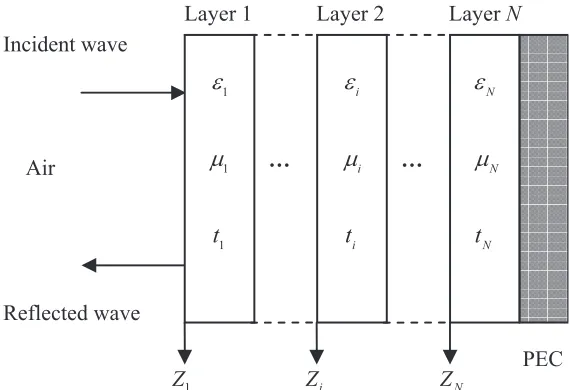
A multilayer absorber consisting of N-layer different materials backed by a perfect electric conductor (PEC) is shown in Fig. 1. The incident wave exists in free space and is normally incident on the first interface [9]. Then, a series of electromagnetic waves propagating in the positive direction and reflected waves propagating in the opposite direction are generated in the absorption layer. The reflection coefficient R at the interface between free space and the absorber can be calculated by using the following equations [6, 13, 14]:
R(f) = Z1−η0
Z1+η0
(1)
where η0 is the intrinsic impedance of free space, η0 = 377 ohms; Z1 is the total impedance of the absorber. According to the transmission line theory, the input impedance of the i-th layer for the normal incident electromagnetic wave is expressed as follows [6, 15]:
Zi =
⎧ ⎨ ⎩
ηiZiη +1+jηitan (βiti)
i+jZi+1tan (βiti) i < N jηitan (βiti) i=N
(2)
whereηi,ti andβi are the wave impedance, thickness and phase constant of thei-th layer, respectively; j is an imaginary unit. The impedance of the last material (i=N) shows that it is close to the perfect
Incident wave
… …
1
Z Zi ZN
PEC Air
Reflected wave
i
ε
i
μ
i
t
N
ε
N
μ
N
t
1
ε
1
μ
1
t
Layer 1 Layer 2 Layer N
conductor. ηi and βi are defined as follows:
ηi =
μi
εi (3)
βi = 2πf
c √
μiεi (4)
where μi and εi are the relative permeability and relative permittivity of the i-th layer of material, respectively; f is the frequency;c is the velocity of light.
This multilayer absorber structure has been solved by using the transmission line theory, and the input impedance Zi of each layer is obtained. In addition, the operational characteristics of the multilayer absorber can be analyzed using the equivalent circuit diagram of the series transmission line of Fig. 2. Given these conditions, the absorber is designed to obtain a set of layers that minimize the maximum reflection coefficient within the previously defined frequency band. Thus, the objective function can be expressed as follows:
Fobj= 20 log10{max|R(f)|, f ∈B} (5) whereB is the frequency band; max|R(f)|is the maximum reflection coefficient of multilayer structure; 20 log10|R(f)|[14] is the reflection loss, expressed in dB.
…
… …
…
1
N
Z − ZN i
Z
1
Z 0
Z (Air)
1 N
Z + (PEC) Incident wave
Figure 2. Equivalent circuit of multilayer absorber.
Multilayer absorbers need to consider the electromagnetic properties and thickness of each coating, so its design needs to optimize 2N parameters. This is a nonlinear multivariate optimization that takes into account continuous variables such as thickness and frequency, as well as discrete variables such as a combination of coatings. In this paper, the binary coding method is used to solve the multilayer microwave absorber design problem. Binary lightning search algorithm (BLSA) is adopted for the design because it has a high search accuracy to solve the binary optimization problem. In order to further improve the BLSA, simulated annealing (SA) will be combined.
3. HYBRID BLSA-SA FOR MULTILAYER ABSORBER
In this section, we mainly introduce a hybrid algorithm of binary lightning search algorithm and simulated annealing (BLSA-SA) and apply it to the design of multilayer microwave absorber.
3.1. Lightning Search Algorithm
the thunder cell in a random direction. Therefore, the transition projectile PT = [pT1, pT2, . . . , pTK] can be modeled as a random number drawn from the standard uniform probability distribution as follow:
fxT=
⎧ ⎨ ⎩
1
b−a fora < x
T ≤b
0 elsewhere
(6)
where xT is a random number that may provide a solution; a and b are the lower and upper bounds, respectively, of the solution space.
The position of the space projectile PS = [pS1, pS2, . . . , pSK] atstep+ 1 can be modeled as a random number generated from the exponential distribution with shaping parameter μas follow:
fxS=
⎧ ⎨ ⎩
1
μe
−xS
μ for xS>0
0 for xS≤0
(7)
Thus, the position and direction ofpSk at step+ 1 can be written as follow:
pSk new =pSk±exprand(μk) (8)
where exprand is an exponential random number; μk is the distance between the space projectile pSk and lead projectile pL;pSk new is the new projectile and pSk the old projectile.
The lead projectile pL moves closer to the ground as the current optimal solution, which can be modeled as a random number taken from the standard normal distribution as follow:
fxL = 1
σ√2πe
−(xL−μ)2
2σ2 (9)
This projectile can search in all directions from the current position defined by the shape parameter (μL). It also has an exploitation ability defined by the scale parameter (σL). The scale parameter σL exponentially decreases as the projectile progresses toward the earth or as it finds the best solution. Thus, the position ofpL at step+ 1 can be written as follow:
pLnew=pL+normrand(μL, σL) (10)
where normrand is a random number generated by the normal distribution function; pLnew is the new projectile lead.
In addition, forking is an important property of a stepped leader, and it will have two simultaneous and symmetrical branches. In the LSA, forking is implemented in two ways. First, symmetrical channels are created because the nuclei collision of the projectile is expressed by using the opposite number as follow:
pk=a+b−pk (11)
wherepk andpk are the opposite and original projectiles, respectively;aandbare the boundary limits. In order to maintain the population size, the forking leader selects pk orpk with a better fitness value. Second, a channel is assumed to appear at the current lead projectile pL tip because of the energy redistribution of the most unsuccessful leader after several propagation trials. The unsuccessful leader can be redistributed by defining the maximum allowable number of trials as channel time.
3.2. Binary Lightning Search Algorithm
The standard LSA is suitable for continuous problems, but it cannot solve the design of multilayer absorbers using binary codes. The following describes the binary variant of LSA — binary lightning search algorithm (BLSA).
Tf(pk), which is interpreted as a probability gate, is designed according to Eq. (12) to map a binary search space. Then, the projectile’s position at step+ 1 is updated following the probability function with a condition as shown in Eq. (13).
Tf(pk) = |tanh (pk)| (12)
Pk new =
pk, ifrand≤ |Tf(pk)|
pk, otherwise (13)
whererand is the uniform random variable in [0, 1].
For the optimization of multilayer absorber design, projectiles (also called individuals) are encoded by binary strings. In this study, the binary string of each individual represents a design scheme of the N-layer absorber, which can be expressed as follows:
Sk=m1m2, . . . , mNt1t2, . . . , tN, k= 1,2, . . . , K (14)
where Sk is the binary string of thek-th individual; K is the population size of the BLSA;mi and ti are the coding of the kind and thickness of thei-th layer material, respectively.
3.3. Simulated Annealing
Simulation algorithm is introduced to avoid the BLSA to fall into the local optimum when finding the best parameter values of the multilayer absorber. The SA was proposed by Kirkpatrick et al. in 1983 to deal with complex nonlinear problems [12]. It is inspired from thermodynamics to simulate the physical process of annealing of molten metals. The main difference between simulated annealing and other heuristic algorithms is the update operation. It not only accepts the better solution of the next generation, but also accepts the poor solution at a certain probability. The SA algorithm determines whether the next solution is accepted according to the Metropolis criteria [17] shown in Eq. (15).
P =
⎧ ⎨ ⎩
1, if ΔE <0
exp −ΔE T
otherwise (15)
Step 1: Initialize population, iteration and channel time of the BLSA, crossover probability and mutation probability.
Step 2: Randomly generate step leaders according to Eq. (6), transition projectiles are encoded by binary strings representing the design of the multilayer microwave absorber.
Step 3: Calculate the projectile energy Esl.
Step 4: Enter the main loop, update best and worst step leaders and the current best maximum reflection coefficient of the absorber.
Step 5: If the maximum channel time is reached, the bad channel (solution) is eliminated and replaced with the best, otherwise go to step 6.
Step 6: Update the direction of projectiles, then eject space and lead projectiles using Eqs. (8) and (10) to generate the sub-projectiles.
Step 7: The sub-projectiles are mapped to the binary search space using Eq. (13).
Step 8: Calculate the sub-projectile energy EP.
Step 9: IfEP < Esl update the projectile position and energy and occur forking, otherwise keep the original position. When the forking occurs, create two symmetrical channels at the fork and select a better channel to enter the next generation.
Step 10: Perform the crossover operation and then perform simulated annealing.
Step 11: Perform the mutation operation and then perform simulated annealing.
whereTis temperature parameter; ΔE(=E−E) is the difference between the current energyE=f(x) and the next solution’s energy E =f(x). The energy here is similar to the energy of the LSA, which corresponds to the objective function value in the optimization problem. As the simulation proceeds, the temperatureT gradually decreases, which is a cooling process. It means that the acceptance probability is getting smaller, and the algorithm finally obtains the global optimum solution.
3.4. Proposed Hybrid BLSA-SA
Hybrid BLSA-SA algorithm takes BLSA as the main process. In order to introduce the simulated annealing mechanism, BLSA is added to the crossover and mutation operation to further optimize the population. At each iteration, the crossover operation chooses a specified number of individuals into a pool based on the crossover probability Pc and randomly selects two individuals in the pool to perform two-point crossover to produce the same number of sub-individuals. In addition, the mutation operation is performed for each dimension of each individual according to a smaller mutation probability Pm. Whether the sub-individuals obtained by the crossover and mutation operations can replace their parents are based on simulated annealing.
The implementation of the hybrid BLSA-SA algorithm consists of two parts. First, according to the evolution of the BLSA algorithm, a better group is generated, which focuses on the global search capability, and then applies the crossover and mutation operations to perform simulated annealing to further improve the accuracy of the solution, which focuses on local search. The process of BLSA-SA in this study is as in the above table.
A flowchart of BLSA-SA is shown in Fig. 3.
4. RESULTS AND ANALYSIS
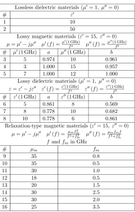
This section presents three design examples to illustrate the advantages of applying the hybrid BLSA-SA algorithm to design multilayer microwave absorbers. The BLBLSA-SA-BLSA-SA results are compared with those of the standard LSA and those published in the literature obtained by other heuristic algorithms. The optimization strategy focuses on selecting the best material from a previously constructed material database. In this study, the database employs 16 different materials [3], and their relative permittivity and permeability are summarized in Table 1. These materials have been widely used in the literature [1– 3, 6–9]. In addition, the best design parameters obtained from other algorithms in the literature, including the material and thickness of each layer, are used to calculate the reflection coefficient for this design over a specified frequency range. And the maximum reflection coefficient and reflection coefficient curve in the frequency range are the same as those given in the literature, which proves that the following experimental simulation has some reliability.
In the design example, the maximum thickness of each layer is set to 2 mm. Thus, the BLSA-SA algorithm can use 4 bit and 12 bit binary strings to represent the material type mi and thickness ti of each layer, respectively. In the binary string representing the thickness, the first 2 bits are the integral part, and the last 10 bits are the fractional part. According to Eq. (14), the length of the binary string of the algorithm’s individual is 16N.
The BLSA-SA and LSA algorithms run under MATLAB R2012a using an Intel(R) Xeon(R) CPU E5-1620 v3 @ 3.50 GHz processor and 8.00 GB memory.
4.1. First Example (Five-Layer Design)
The absorber is composed of five layers to minimize the reflection coefficient in the frequency range of 2–8 GHz. The design results of BLSA-SA are compared with the results of the following five heuristic algorithms: lightning search algorithm (LSA), particle swarm optimization (PSO), gravitational search algorithm (GSA) [18], differential evolution (DE) [8] and central force optimization (CFO) [19]. The data for the last four algorithms can be found in [9]. The frequency step is 0.5 GHz, and the maximum total thickness of the absorber is 5 mm. In this experiment, each individual of the BLSA-SA algorithm is represented by an 80-bit binary string. Each algorithm runs 20 times independently, and the number of iterations is 1000. Other control parameters associated with all algorithms are as follows [9]:
Start
Initialize variables
Randomly generate step leaders using binary strings (transition projectile)
Evaluate performance ( projectile energies,Esl)
Update best and worst step leaders
Mapped to binary search space
Evaluate performance ( sub-projectile energies,Ep)
Max channel time?
Update direction, eject space and lead projectiles
Eliminate bad channel (Move step leader from worst to best)
Reset channel time Yes
No
Increase iteration and channel time
Perform crossover operation, simulated annealing evolution
Perform mutation operation, simulated annealing evolution
Max iteration?
Return the best design
End Yes No
Yes Yes Extend channel
(EP Esl) ?
Forking occurs?
Create two symmetrical channels at fork point
No No
Eliminate channel which has lower energy New position
Remain position
Update step leaders
<
Table 1. Predefined material database.
Lossless dielectric materials (μ = 1, μ= 0)
# ε
1 10
2 50
Lossy magnetic materials (ε = 15, ε= 0) μ=μ−jμ μ(f) = μ(1 GHz)fa μ(f) = μ(1 GHz)fb
# μ(1 GHz) a μ(1 GHz) b
3 5 0.974 10 0.961
4 3 1.000 15 0.957
5 7 1.000 12 1.000
Lossy dielectric materials (μ = 1, μ= 0) ε=ε−jε ε(f) = ε(1 GHz)fa ε(f) = ε
(1 GHz)
fb
# ε(1 GHz) a ε(1 GHz) b
6 5 0.861 8 0.569
7 8 0.778 10 0.682
8 10 0.778 6 0.861
Relaxation-type magnetic materials (ε= 15, ε= 0)
μ=μ−jμ μ(f) = fμ2m+ffm22
m μ
(f) = μmfmf
f2+f2 m
f and fm in GHz
# μm fm
9 35 0.8
10 35 0.5
11 30 1.0
12 18 0.5
13 20 1.5
14 30 2.5
15 30 2.0
16 25 3.5
BLSA-SA parameter setting: population sizeK = 50, channel time T = 10, forking rate r= 0.01, crossover probability Pc = 0.5, mutation probability Pm = 0.05, annealing initial temperature Tsa= 1 and temperature cooling coefficientCsa= 0.998.
PSO parameter setting: population size K = 100, self cognition c1 = 2, social cognition c2 = 2, wmax= 0.95 andwmin= 0.4.
GSA parameter setting: population sizeK = 20,G0 = 100, α= 20 and Rnorm = 2.
DE parameter setting: stopping criterion ε= 10−7, differentiation factor F ∈ [0.5, 1], crossover constant CR∈[0, 1] and population size is unknown.
CFO parameter setting: population size K = 20, acceleration clipping Amax = 0.1, G = 1.7, α= 0.6,β = 0.9 andFrep = 0.9.
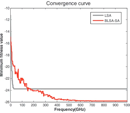
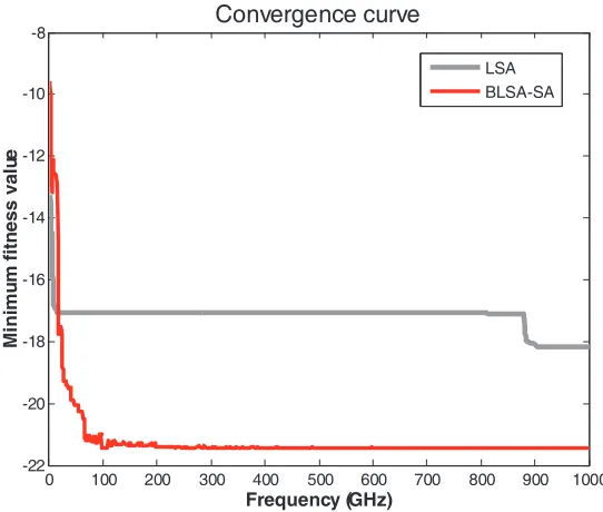
Moreover, the convergence curve of BLSA-SA has a retrogression phenomenon because it incorporates the simulated annealing mechanism, which accepts a solution worse than the current solution with a certain probability, but eventually converges to the minimum, indicating that the BLSA-SA algorithm has the ability to avoid falling into the local optimum. Table 3 presents the statistical results of the maximum reflection coefficient (best, worst, mean and standard deviation values) for each algorithm. It can be seen that the BLSA-SA is more stable than other algorithms when designing such a five-layer absorber.
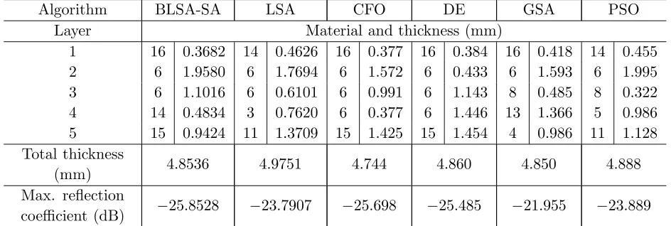
Table 2. Best design results for five-layer design (frequency range 2–8 GHz, max. total thickness 5 mm).
Algorithm BLSA-SA LSA CFO DE GSA PSO
Layer Material and thickness (mm)
1 16 0.3682 14 0.4626 16 0.377 16 0.384 16 0.418 14 0.455
2 6 1.9580 6 1.7694 6 1.572 6 0.433 6 1.593 6 1.995
3 6 1.1016 6 0.6101 6 0.991 6 1.143 8 0.485 8 0.322
4 14 0.4834 3 0.7620 6 0.377 6 1.446 13 1.366 5 0.986
5 15 0.9424 11 1.3709 15 1.425 15 1.454 4 0.986 11 1.128 Total thickness
(mm) 4.8536 4.9751 4.744 4.860 4.850 4.888
Max. reflection
coefficient (dB) −25.8528 −23.7907 −25.698 −25.485 −21.955 −23.889
2 3 4 5 6 7 8
-32 -31 -30 -29 -28 -27 -26 -25 -24 -23 -22
Frequency (GHz)
R
e
fl
ec
ti
o
n
co
e
ff
ici
en
t
(d
B
)
PSO GSA DE CFO LSA BLSA-SA
Figure 4. Reflection coefficients described in Table 2.
0 100 200 300 400 500 600 700 800 900 1000 -26
-24 -22 -20 -18 -16 -14 -12 -10
Frequency(GHz)
M
ini
m
u
m
fitn
ess valu
e
Convergence curve
LSA BLSA-SA
Figure 5. Convergence curve for five-layer design.
Table 3. Max. reflection coefficient (in dB) comparative results after 20 trials for five-layer design.
Algorithm Best Worst Mean Standard deviation BLSA-SA −25.8528 −23.9376 −25.0812 0.6842
LSA −23.7907 −18.5161 −21.9058 1.7516 CFO −25.698 −21.848 −23.154 0.988
DE −25.485 −22.760 −24.001 0.784 GSA −21.955 −10.222 −15.552 2.802 PSO −23.889 −19.838 −22.495 1.133
Table 4. Best design results for five-layer design (frequency range 2–8 GHz, max. total thickness 2.57 mm).
Algorithm BLSA-SA LSA CFO DE GSA PSO
Layer Material and thickness (mm)
1 16 0.5635 14 0.5847 16 0.561 16 0.562 16 0.575 16 0.397
2 7 0.5488 6 0.6810 7 0.850 7 0.897 1 0.574 14 0.201
3 6 0.3301 2 0.8137 2 0.393 2 0.408 2 0.345 2 0.658
4 2 0.4141 15 0.4667 13 0.158 15 0.592 9 0.355 13 0.524 5 15 0.7080 9 0.0239 15 0.605 15 0.111 9 0.699 11 0.353 Total thickness
(mm) 2.5645 2.5700 2.569 2.57 2.550 2.134
Max. reflection
2 3 4 5 6 7 8 -3 6
-3 4 -3 2 -3 0 -2 8 -2 6 -2 4 -2 2 -2 0 -1 8
Re
fl
ec
ti
on
coef
fi
ci
en
t
(d
B)
PSO GSA DE CFO LSA BLSA- SA
Frequency (GHz)
Figure 6. Reflection coefficients described in Table 4.
0 100 200 300 400 500 600 700 800 900 1000
-22 -20 -18 -16 -14 -12 -10
Frequency (GHz)
Ma
x.
re
fl
ec
ti
on
coe
ffi
ci
en
t
(d
B)
Convergence curve
LSA BLSA-SA
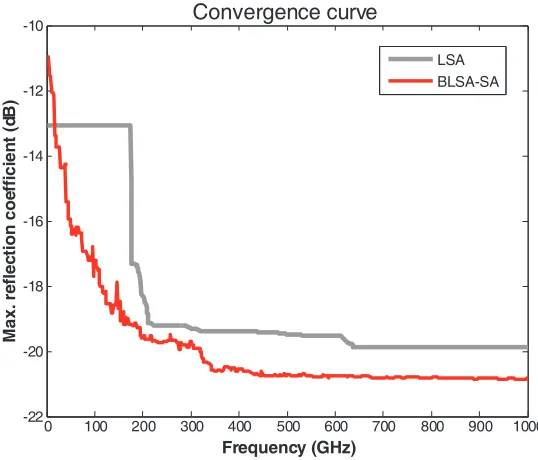
Figure 7. Convergence curve for thinner five-layer design.
presents the statistical results of the maximum reflection coefficient for each algorithm. It shows that the BLSA-SA has good stability in the results of 20 independent tests.
4.2. Second Example (Seven-Layer Design)
Table 5. Max. reflection coefficient (in dB) comparative results after 20 trials for thinner five-layer design.
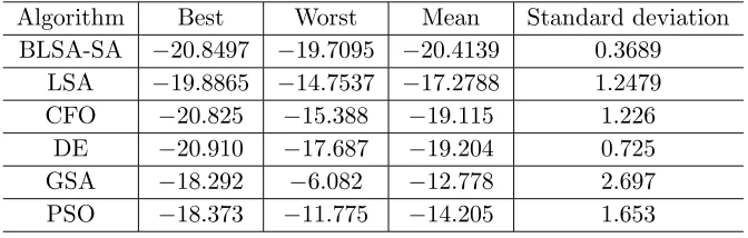
Algorithm Best Worst Mean Standard deviation BLSA-SA −20.8497 −19.7095 −20.4139 0.3689
LSA −19.8865 −14.7537 −17.2788 1.2479 CFO −20.825 −15.388 −19.115 1.226
DE −20.910 −17.687 −19.204 0.725 GSA −18.292 −6.082 −12.778 2.697 PSO −18.373 −11.775 −14.205 1.653
Table 6. Best design results for seven-layer design.
Algorithm BLSA-SA1 BLSA-SA2 LSA CFO MLPSO
Layer Material and thickness (mm)
1 16 0.2080 16 1.8369 14 0.2925 16 0.2102 14 0.21267
2 6 1.7490 6 0.2051 6 1.4500 6 1.8485 6 2.1786
3 16 0.0850 16 0.5508 4 0.8872 14 0.5678 14 0.50102
4 6 0.0820 5 1.8076 6 1.2718 5 1.6820 6 1.1592
5 14 0.4922 6 1.9541 4 1.3003 4 1.2007 5 1.7043
6 5 1.5020 4 1.4756 2 1.1209 4 0.2630 6 2.1965
7 4 1.6602 8 0.0488 3 0.7397 3 0.0894 5 1.6561
Total thickness
(mm) 5.7784 7.8789 7.0624 5.861 9.6
Max. reflection
coefficient (dB) −18.0406 −18.4670 −15.9701 −17.924 −18.5
0 2 4 6 8 10 12 14 16 18 20
-24 -23 -22 -21 -20 -19 -18 -17 -16 -15
Freq uency (GH z)
Re
fl
ect
io
n coef
fi
ci
en
t
(d
B)
PSO CFO LSA BLSA- SA2 BLSA- SA1
0 100 200 300 400 500 600 700 800 900 1000 -20
-15 -10 -5
Frequency (GHz)
M
a
x
. r
e
fle
c
tion
coeffi
cien
t (
d
B
)
Convergence curve
LSA BLSA-SA2 BLSA-SA1
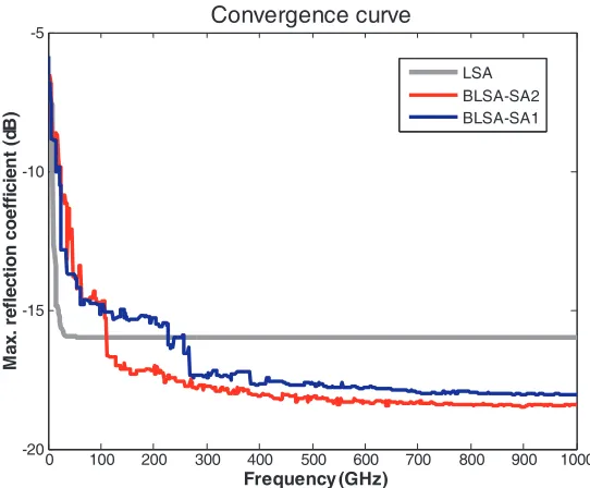
Figure 9. Convergence curve for seven-layer design.
coefficient and total thickness of BLSA-SA1 are better than CFO. The maximum reflection coefficient of BLSA-SA2 is close to MLPSO, and its total thickness is much thinner. Fig. 8 shows the reflection coefficients of the seven-layer absorber optimized by four algorithms. The convergence curves of BLSA-SA and LBLSA-SA are shown in Fig. 9. It can be found that the convergence accuracy of BLBLSA-SA-BLSA-SA1 and BLSA-SA2 is higher than that of LSA.
4.3. Third Example (Three-Layer Design)
This example presents the design of a three-layer microwave absorber in the frequency range of 0.85 GHz to 5.4 GHz belonging to the wireless communication. Each individual of the BLSA-SA is encoded by a 48-bit binary string. The best optimization results of BLSA-SA are compared with the results of LSA and unified particle swarm optimization (UPSO) [6], as shown in Table 7. It can be found that the optimization results of BLSA-SA agree with those obtained by UPSO. However, the LSA optimization results are not that good. It is shown that the feasibility of the BLSA-SA algorithm to optimize the three-layer absorber, although the limited results reproducibility persists. The reflection coefficients of the absorber designed by BLSA-SA, LSA and UPSO are shown in Fig. 10. Fig. 11 shows the convergence curves of BLSA-SA and LSA, in which the convergence accuracy of BLSA-SA is obviously higher than that of LSA.
Table 7. Best design results for three-layer design.
Algorithm BLSA-SA LSA PSO
Layer Material and thickness (mm) 1 16 0.5996 15 0.8488 16 0.599916
2 3 1.9990 2 1.0378 3 1.999552
3 4 1.6299 5 1.9994 4 1.627319
Total thickness
(mm) 4.2285 3.8860 4.2268
Max. reflection
0.5 1 1.5 2 2.5 3 3.5 4 4.5 5 5.5 -45
-40 -35 -30 -25 -20 -15
Frequency (GHz)
R
e
fl
e
c
tion
coef
fi
cien
t (
d
B
)
UPSO LSA
BLSA-SA
Figure 10. Reflection coefficients described in Table 7.
0 100 200 300 400 500 600 700 800 900 1000
-22 -20 -18 -16 -14 -12 -10 -8
Frequency (GHz)
Mi
ni
mu
m
fi
tn
ess
valu
e
Convergence curve
LSA BLSA-SA
Figure 11. Convergence curve for three-layer design.
5. CONCLUSIONS
5 mm and 2.57 mm, respectively. The BLSA-SA algorithm has better maximum reflection coefficient and total thickness than other algorithms in both cases. Moreover, the BLSA-SA algorithm has the minimum standard deviation after 20 independent runs, indicating that the BLSA-SA is more stable than other algorithms. In the seven-layer design, the BLSA-SA achieves very small maximum reflectance (−18.0406 dB) and very thin thicknesses (5.7784 mm) over a wide frequency range (0.1–20 GHz). In addition, the BLSA-SA optimization results are consistent with the UPSO in the three-layer design, which illustrates the feasibility of the BLSA-SA algorithm for designing the three-layer absorber.
The optimized design of the multilayer absorber in this study only discusses the case of vertical incidence of electromagnetic waves. The incidence of electromagnetic waves in the multi-angle or range of angles will be discussed in future studies. There are sixteen fictional materials used to validate the effectiveness of the proposed algorithm. Future research should introduce more new and practical absorbent materials. The design problem of multilayer microwave absorbers is to make the absorber’s reflection coefficient and the total thickness as small as possible, which can be considered as two objective functions [2, 5]. The hybrid BLSA-SA algorithm will be used to solve this multi-objective problem and compared with other algorithms to verify its performance.
ACKNOWLEDGMENT
This work was supported by the National Natural Science Foundation of China under Grant Nos. 61463007, 61563008 and Project of the Guangxi Natural Science Foundation under Grant No. 2016GXNSFAA380264.
REFERENCES
1. Weile, D. S., E. Michielssen, and D. E. Goldberg, “Genetic algorithm design of Pareto optimal broadband microwave absorbers,” IEEE Trans. Electromagn. Compat., Vol. 38, No. 3, 518, 1996. 2. Jiang, L., J. Cui, L. Shi, and X. Li, “Pareto optimal design of multilayer microwave absorbers for
wide-angle incidence using genetic algorithms,”IET Microw. Antennas Propag., Vol. 3, 572, 2009. 3. Michielssen, E., J. M. Sajer, S. Ranjithant, and R. Mittra, “Design of lightweight, broad-band microwave absorbers using genetic algorithms,” IEEE Trans. Microwave Theory Tech., Vol. 41, No. 6/7, 1024, 1993.
4. Cui, S. and D. S. Weile, “Application of a parallel particle swarm optimization scheme to the design of electromagnetic absorber,” IEEE Trans. Antennas Propagat., Vol. 53, No. 11, 3616, 2005. 5. Goudos, S. K. and J. N. Sahalos, “Microwave absorber optimal design using multi-objective particle
swarm optimization,” Microwave and Optical Technology Letters, Vol. 48, No. 8, 1553, 2006. 6. Amaya, I. and R. Correa, “Optimal design of multilayer EMAs for frequencies between 0.85 GHz
and 5.4 GHz,” Revista de Ingenieria, Vol. 38, 33, 2013.
7. Goudos, S. K., “Design of microwave broadband absorbers using a self-adaptive differential evolution algorithm,”Int. J. RF and Microwave CAE, Vol. 19, 364, 2009.
8. Dib, N., M. Asi, and A. Sabbah, “On the optimal design of multilayer microwave absorbers,” Progress In Electromagnetics Research C, Vol. 13, 171, 2010.
9. Asi, M. J. and N. I. Dib, “Design of multilayer microwave broadband absorbers using central force optimization,” Progress In Electromagnetics Research B, Vol. 26, 101, 2010.
10. Islam, M. M., H. Shareef, A. Mohamed, and A. Wahyudie, “A binary variant of lightning search algorithm: BLSA,”Soft Comput., Vol. 21, 2971, 2017.
11. Shareef, H., A. A. Ibrahim, and A. H. Mutlag, “Lightning search algorithm,”Appl. Soft Comput., Vol. 36, 315, 2015.
12. Kirkpatrick, S., C. D. Gelatt, Jr., and M. P. Vecchi, “Optimization by simulated annealing,” Science, Vol. 220, 671, 1983.
14. Du, M., Z. J. Yao, J. T. Zhou, P. J. Liu, T. T. Yao, and R. Yao, “Design of efficient microwave absorbers based on multi-layered polyaniline nanofibers and polyaniline nanofibers/Li0.35Zn0.3Fe2.35O4 nanocomposite,”Synthetic Metals, Vol. 223, 49, 2017.
15. Bronwel, A., “Transmission-line analogies of plane electromagnetic-wave reflections,” Proceedings of the I.R.E., Vol. 32, 233, 1944.
16. Ahmed, M. S., A. Mohamed, R. Z. Homod, and H. Shareef, “Hybrid LSA-ANN based home energy management scheduling controller for residential demand response strategy,” Energies, 2016. 17. Metropolis, N., A. W. Rosenbluth, M. N. Rosenbluth, and A. H. Teller, “Equation of state
calculations by fast computing machines,”J. Chem. Phys., Vol. 21, No. 6, 1087, 1953.
18. Rashedi, E., H. Nezamabadi-Pour, and S. Saryazdi, “GSA: A gravitational search algorithm,” Information Sciences, Vol. 179, 2232, 2009.
19. Formato, R. A., “Central force optimization: A new metaheuristic with applications in applied electromagnetics,” Progress In Electromagnetics Research, Vol. 77, 425, 2007.