Compact
1
×
2
and
2
×
2
MIMO Antennas with Enhanced Isolation
for Ultrawideband Application
Hui Li*, Jinhai Liu, Ziyang Wang, and Ying-Zeng Yin
Abstract—Two small size multiple-input–multiple-out (MIMO) antennas with high isolation for
ultrawideband (UWB) applications are presented. A two-element MIMO antenna, which is mounted on an FR4 substrate with a compact size of 24 mm×33 mm, consists of two symmetric circular monopole elements and a modified ground. The protruded ground provides a way to improve isolation and impedance matching. Such a wide band from 2.75 to 11 GHz is achieved by using modified ground technology, and high isolation more than 20 dB is also accomplished. Meanwhile, moderate gain and omnidirectional radiation patterns can be obtained. Based on the circular monopole with modified ground, a four-element antenna array is also constructed and studied. The size of the four-element antenna with orthogonal arrangement is 44 mm×44 mm. Measured results show that the antenna also exhibits good impedance matching as well as low envelope correlation coefficient over the entire UWB spectrum.
1. INTRODUCTION
Ultrawideband (UWB) technology has recently attracted significant attention in wireless communica-tions due to its attractive characteristics such as rapid data rate, low power and low cost. In 2002, the Federal Communication Commission (FCC) announced that the frequency spectrum of 3.1–10.6 GHz can be commercially available for UWB applications. Multiple-input–multiple-output (MIMO) technology is well known for overcoming the effects of multipath fading. Therefore, it is a sensible way to introduce MIMO technology in the UWB systems to improve channel capacity, and thus additional power require-ments become not necessary [1, 2]. When multiple antennas are applied in portable devices, the mutual coupling between the antenna elements will increase, and of course the MIMO antenna performance will deteriorate. Thus, the major problem in MIMO antenna designs is to suppress the mutual coupling while maintaining a compact antenna configuration. Recently, various decoupling methods have been reported in open literature [3–13]. Usually, antenna elements of different types combined in [3, 4] can achieve high isolation, yet the MIMO antennas possess different impedance matchings and radiation characteristics between ports. A tree-like structure extending from the ground is adopted in [5] to cut down the wideband mutual coupling between the radiating elements. By using the parasitic elements, the MIMO antennas in [6, 7] achieve isolation enhancement over a wide bandwidth. However, the wide-band decoupling methods often make the antennas relatively large in size and complicated in structure. In [8–10], orthogonal radiation patterns with low correlation are obtained by the orthogonal placement of antenna elements and hence result in high port isolation. On this basis, several methods are proposed to further minimize the overall size of the MIMO antennas. Coradiator technology is a very effective way to miniaturize the conventional antennas in [11, 12]. Another miniaturization technique is employing
Received 8 December 2016, Accepted 7 January 2017, Scheduled 26 January 2017 * Corresponding author: Hui Li (huiyuezai@163.com).
42 Li e al.
the asymmetric coplanar strip (ACS) structures, and the antenna presented in [13] occupies a small size of 28.5×28.5 mm2. However, the MIMO antennas in [11–13] exhibit an isolation level of only 15 dB.
In this paper, two MIMO antennas with enhanced isolation for UWB applications are presented. The two-element antenna has a planar size of 24×33 mm2, which is even smaller than the design
in [13]. By adopting the protrude ground, the operating bandwidth of the antenna can be improved, and the mutual coupling between antenna elements can be suppressed. Moreover, with the help of a reverse T-shaped slot on the ground, further enhancement in isolation at the lower band is realized. A UWB MIMO antenna in a four-element configuration is also constructed by orthogonally arranging the antenna elements. And quarter-wavelength slits are employed on the ground to mitigate mutual coupling between the adjacent antenna ports. Results of two MIMO antennas illustrate that these antennas are good candidate for UWB application.
2. 1×2 UWB MIMO ANTENNA DESIGN
2.1. Antenna Model
As shown in Fig. 1, the geometry of the two-element UWB MIMO antenna is proposed. It is implemented with an FR4 substrate which hasεr= 4.4 andh = 1 mm. The two-port MIMO antenna only occupies an overall dimension of 24×33 mm2.
Figure 1. Proposed two-element MIMO antenna.
The proposed antenna comprises two circular monopole elements symmetrically arranged and a modified ground plane. All elements are fed by 50-Ω transmission line, which is tapered to optimize the impedance matching to the circular radiator. The modified ground plane consists of a traditional ground part and a protruded ground part. By using the protruded ground, the antenna impedance bandwidth can be widened while total antenna size remains unchanged. Meanwhile, the port isolation at the higher operating band can be enhanced. The mutual coupling in lower band is obtained by reverse T-shaped slot etched on the ground plane. To estimate the antenna performance, the full-wave solver ANSYS High Frequency Structure Simulator (HFSS 14) soft-ware is employed. The final parameters are listed as follows (in millimetres): W = 33, L = 24, WG = 31, d = 16.1, wf1 = 1.9, wf2 = 0.5, ws= 0.4,LG= 10, lf1 = 5,lf2= 5.5, ls1 = 9.4,ls2 = 6.5, R= 13.2, andr= 4.
2.2. Effects of Modified Ground Plane
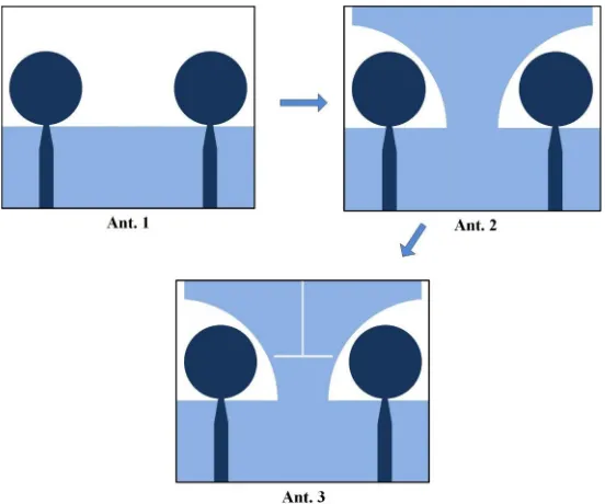
Figure 2. Evolution of the MIMO antennas with different ground structures.
(a) (b)
Figure 3. Corresponding|S11|and |S12|with different ground structures.
a lower cutoff frequency equally to reduce the oversize of antenna. The mutual coupling at the band over 4 GHz of Ant. 2 is better than that of Ant. 1. This is because the protruded ground can also be considered as a reflector to separate the radiation patterns of the two radiators, which helps to reduce the mutual coupling between the two ports. Then, Ant. 3 is formed by etching the reverse T-shaped slot on the ground. It can be seen from Fig. 3 that the mutual coupling at the band about 3–4.4 GHz is improved to better than −20 dB with a slight effect on the impedance matching. It is noted that the T-shaped slot has an overall length of 2∗ls1 −ws + 2∗ls2 = 31.4 mm, which is a little longer
than one half of the guided wavelength at 3.5 GHz. Thus, the slot can serve as a resonator, and strong current can be induced near it at the resonant frequency. The current distributions with the reverse T-shaped slot (Ant. 3) compared with Ant. 2 are applied in Fig. 4. It is found that larger surface current is mainly concentrated along the T-shaped slot, and the surface current on the radiator of the right antenna element becomes much less. Due to the symmetry of the structure and the excitation, the same results can be observed while Port 2 is excited.
44 Li e al.
(a)
(b)
Figure 4. Simulated surface current distributions at 3.5 GHz without (a) and with (b) reverse T-shaped
slot.
Figure 5. Fabricated prototype of Ant. 3.
(a) (b)
Figure 6. Simulated and measuredS-parameters of Ant. 3.
results. Measured results indicate thatS11 is below−10 dB from 2.75 to 11 GHz while mutual coupling (S12/S21) is more than 20 dB throughout the operating band. It is clear that the discrepancies between measurement and simulation are very slight, which proves that the design structure has a good and stable performance.
the proposed antenna produces quasi-omnidirectional patterns in thexoy-plane and nearly bidirectional patterns in thexoz-plane. Due to the symmetry property of the MIMO antenna, the other port exhibits similar radiation patterns. In addition, the measured peak gain and radiation efficiency of the two-element MIMO antenna are shown in Fig. 8. It is clear from the figure that the gain is stable with less than 2.5 dB variation, and the radiation efficiency is above 70% across the UWB spectrum.
The diversity performance of the dual-element MIMO antenna can be evaluated by the envelope correlation coefficient (ECC). An ECC level below 0.5 is set as an accepted limit for diversity conditions [14]. Assuming that the antenna operates in a uniform multipath environment, the ECC value can be derived from the measuredS-parameters [15]. As observed in Fig. 9, the ECC (denoted by
ρe, 12) between Port 1 and Port 2 is found below 0.02 across the whole working band, which is much less than 0.5 to ensure good MIMO performance. A comparison of the proposed two-element MIMO antenna with several representative MIMO antennas is presented in Table 1.
Figure 7. Measured radiation patterns of the Ant. 3 at 3.5, 6.5, and 9.5 GHz.
Figure 8. Simulated and measured gain of Ant.
3.
Figure 9. Simulated and measured envelope
46 Li e al.
Table 1. Comparison of various two-element MIMO antennas.
Ref. No. Antenna size(mm3) Bandwidth(GHz) Mutual coupling(dB) Gain Variation(dB)
[4] 25×40×1.55 = 1550 3.1–5.15 <−20 1.5&4.5
[5] 35×40×0.8 = 1120 3.1–10.6 <−16 3.1
[8] 33×45.5×1.254 = 1882.9 3.1–10.6 <−20 2.3
[10] 32×32×0.8 = 819.2 3.1–10.6 <−15 2.5
[13] 28.5×28.5×1.6 = 1299.6 2.66–11.08 <−15 2.2
Pro. 24×33×1 = 792 2.75–11 <−20 2.5
3. 2×2 MIMO ANTENNA ARRAY
When more antenna elements are added in the multi-antenna system, the channel capacity of system will increase without additional spectrum and power consumption. Therefore, the 2×2 UWB MIMO antenna is designed. The schematic diagram and fabricated structure of MIMO antenna with four elements are shown in Fig. 10. The proposed antenna is designed on a 1 mm-thick FR4 substrate with a very small size of 44×44 mm2 (refer to Ant. 4). Compared with the existing four-element MIMO
antennas [16–19], this one still has the advantage in size and simple structure. The monopole antenna with circular radiator and modified ground is also used as the four-port antenna element. To achieve polarization diversity and high isolation, the four elements are placed symmetrically by two diagonal lines and perpendicular to each other. Since all the antenna elements share a common ground plane, which makes the ground current uncontinuity declined. As a result, a better wide-band performance can be achieved. Four rectangular slits that resonate at about quarter-wavelength are introduced on the ground to enhance the isolation between the adjacent antenna ports.
The measuredS-parameters of 2×2 MIMO antenna array are presented in Fig. 11. It is found that the operating bandwidth ranges from 3 to 10.8 GHz, along with mutual coupling better than −20 dB for most of the band (except the band of 3–3.7 GHz which is also below −15 dB). The 3-D radiation patterns of the antenna array system at 5.5 GHz are given in Fig. 12. The antenna radiates toward−y-,
−z-, +y-, and +z-axis directions when corresponding port is excited.
(a) (b)
Figure 11. MeasuredS-parameters of Ant. 4.
(b) (a)
(d) (c)
Figure 12. 3-D radiation patterns of the Ant. 4 at 5.5 GHz.
48 Li e al.
The patterns have weak influence on each other, which weakens the coupling between antenna elements. The antenna provides different radiation patterns to receive signals from different directions, hence ensuring pattern diversity with good isolation. The ECC values between the antenna elements are calculated through measured data. It can be found in Fig. 13 that the ECC values are less than 0.01 for the entire UWB, which proves that this antenna has a good diversity performance. Ant. 4 has much smaller size and better isolation than traditional four-element MIMO antennas, which is attractive for the use in UWB systems.
4. CONCLUSION
Two compact UWB MIMO antennas using modified ground are presented in this paper. The proposed two- & four-element MIMO antennas have total dimensions of 24×33×1 mm3 and 44×44×1 mm3,
respectively. The modified ground of the two-element MIMO antenna consists of a main ground part and a protruded ground part. By employing the protruded ground, not only the impedance bandwidth can be widened, but also the mutual coupling can be reduced. In addition, the two-element antenna uses a reverse T-shaped slot as a decoupling structure. The four-element MIMO antenna is constructed by orthogonally placing the antenna elements with modified ground, which results in pattern diversity and good isolation. Further enhancement in isolation is realized by etching quarter-wavelength slits on the ground. The antenna prototypes have been fabricated and tested. Both the measured and simulated results prove that the proposed antennas are suitable for portable UWB applications.
REFERENCES
1. Kaiser, T., F. Zheng, and E. M. Dimitrov, “An overview of ultra-wide-band systems With MIMO,”
IEEE Proc., Vol. 97, 285–312, 2009.
2. Wallace, J. W., M. A. Jensen, A. L. Swindlehurst, and B. D. Jeffs, “Experimental characterization of the MIMO wireless channel: Data acquisition and analysis,” IEEE Trans. Wirel. Commun.,
Vol. 2, 335–343, 2003.
3. Malik, J., A. Patnaik, and M. V. Kartikeyan, “Novel printed MIMO antenna with pattern and polarization diversity,”IEEE Antennas Wireless Propag. Lett., Vol. 14, 739–742, 2015.
4. Zhang, S., B. K. Lau, A. Sunesson, and S. L. He, “Closely-packed UWB MIMO/Diversity antenna with different patterns and polarizations for USB dongle applications,” IEEE Trans. Antennas Propag., Vol. 60, 4372–4380, 2012.
5. Zhang, S., Z. N. Ying, J. Xiong, and S. L. He, “Ultrawideband MIMO/Diversity antennas with a tree-like structure to enhance wideband isolation,” IEEE Antennas Wireless Propag. Lett., Vol. 8,
1279–1282, 2009.
6. Khan, M. S., A. D. Capobianco, A. I. Najam, I. Shoaib, E. Autizi, and M. F. Shafique, “Compact ultra-wideband diversity antenna with a floating parasitic digitated decoupling structure,” IET Microw. Antennas Propag., Vol. 8, 747–753, 2014.
7. Khan, M. S., M. F. Capobianco, A. D. Shafique, B. Ljaz, A. Naqvi, and B. D. Braaten, “Isolation enhancement of a wideband MIMO antenna using a floating parasitic elements,” Microw. Opt. Technol. Lett., Vol. 57, 1677–1682, 2015.
8. Liu, L., S. W. Cheung, and T. I. Yuk, “Compact MIMO antenna for portable devices in UWB applications,” IEEE Trans. Antennas Propag., Vol. 61, 4257–4264, 2013.
9. Chako, B. P., G. Augustin, and T. A. Denidni, “Uniplanar polarisation diversity antenna for ultrawideband systems,”IET Microw. Antennas Propag., Vol. 7, 851–857, 2013.
10. Ren, J., W. Hu, Y. Z. Yin, and R. Fan, “Compact printed MIMO antenna for UWB applications,”
IEEE Antennas Wireless Propag. Lett., Vol. 13, 1517–1520, 2014.
11. Mao, C. X. and Q. X. Chu, “Compact coradiator UWB-MIMO antenna with dual polarization,”
IEEE Trans. Antennas Propag., Vol. 62, 4474–4480, 2014.
13. Liu, Y. F., P. Wang, and H. Qin, “Compact ACS-fed UWB antenna for diversity applications,”
Electron. Lett., Vol. 50, 1336–1338, 2014.
14. Vaughan, R. G. and J. B. Andersen, “Antenna diversity in mobile communications,”IEEE Trans. Veh. Technol., Vol. 36, 149–172, 1987.
15. Blanch, S., J. Romeu, and I. Corbella, “Exact representation of antenna system diversity performance from input parameter description,” Electron. Lett., Vol. 39, 705–707, 2003.
16. Lin, S.-Y. and H.-R. Huang, “Ultra-wideband MIMO antenna with enhanced isolation,”Microwave and Optical Technology Lett., Vol. 51, 570-573, 2009.
17. Khan, M. S., A.-D-C. S. Asif, A. Iftikhar, and B. D. Braaten, “A 4 element compact ultra-wideband MIMO antenna array,” 2015 IEEE International Symposium on Antennas and Propagation & USNC/URSI National Radio Science Meeting, 2305–2306, 2015.
18. Khan, M. S., A. D. Capobianco, S. Asif, A. Iftikhar, B. Ijaz, and B. D. Braaten, “Compact 4×4 UWB-MIMO antenna with WLAN band rejected operation,” Electron. Lett., Vol. 51, 1048–1050,
2015.