Simulation and Classification of Static NAT and
Dynamic NAT
Aye Aye Mar 1, Lei Yee Kyaw2, May Phyo Ko2,Tint Tint Oo3
123Faculty of Computer System and Technology, University of Computer Studies,(Meikthila)
email:[email protected]
Abstract
Today, every person using internet, so person is used Network Address Translation (NAT) .NAT router to represent the private address to the rest of the internet. Simulation is becoming increasingly
popular among computer network
researchers worldwide in recent years. It is also important to ensure that the results generated by the simulators are valid and credible. In this paper are using simulation tool, static NAT and dynamic NAT methods describe global network address.
1.Introduction
Devices can be access to internet with public address. Public IP address can route on the internet. Internet is the collection of Local Area Network. In the LAN network, devices used the private IP address and these addresses cannot be routed to the internet. Network Address Translation (NAT) translates between Private and Public IP address.
2.Network Address Translation(NAT)
Every IP-capable machine needs a public IP address to connect to the internet. A small office, home office (SOHO) wants to install a LAN to connect multiple machines and a large number of IP address need to be allocated by ISP to cover all of SOHO devices. If the subnet grew bigger, a larger block of addresses would have to be allocated. To solve this problem used NAT router to represent the private address to the rest of the internet. The NAT router, changes the packet’s source IP address
when the packet leaves the private organization and changes the destination address in each packet that is forwarded back into the private network. The NAT-enable router does not look like a router to the outside world. NAT router behaves to the outside world as a signal device with a single IP address. NAT router is hiding the details of the home network from the outside world. If all datagrams arriving at the NAT router from the WAN have the same destination IP address. The trick is to use a NAT translation table at the NAT router.
3.NAT Terminology
Network Address Translation (NAT) allows users to access the internet by sharing one or more public IP address. An IP address is either local or global. Local IPV4 address are seen in the inside network. Global IPV4 addresses are seen in the outside network. As shown in figure 1.
Figure1. NAT Terminology
Inside Local- In a typical NAT design, the term inside refers to an address used for a host inside an enterprise. An inside local is the actual IP address assigned to a host in the private enterprise network. A more descriptive term might be inside private, because oftentimes, the inside address are also private addresses.
Outside global In a typical NAT design, the term outside refers to an address used for a host in the internet. An outside global address is the actual IP address assigned to a host that resides in the outside network. A more descriptive term might be outside public, because the outside global address represents the outside host with a public IP address that can be used for routing in the public internet. Outside local NAT can translate the outside IP address, the IP address that represents the host outside the enterprise network. When a NAT router forwards a packet from the inside network to the outside, when using NAT to change the outside address, the IP address that represents the outside host as the destination IP address in the packet is called the outside local address.
4. Topology for Configuring Static NAT
Using NAT terminology, the enterprise network that uses private address, needs NAT, is the “inside” part of the network. The internet side of the NAT function is the “outside” part of the network. The topology consists of three pc’s (PC0, PC1 &PC2), one server (server0), two switch’s (2950-24), two routers (1841) and connecting wires. R0 is assumed to be connected to ISP & R1 on the WAN side. This topology is show in figure 2.
Figure 2.Topology for Configuration
5.Configuration of Static NAT for the Considered Topology
Static NAT is used for server side configuration. One-to-one mapping of a private IP address to a public IP address. Static NAT is useful when a network device inside a private network needs to be
accessible from internet. After constructing
the network and making connections as described in the above figure, IP addresses
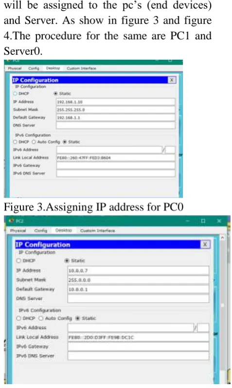
will be assigned to the pc’s (end devices) and Server. As show in figure 3 and figure 4.The procedure for the same are PC1 and Server0.
Figure 3.Assigning IP address for PC0
Figure 4.Assigning IP address for PC2
5.1Router 0 Configuration
--- System Configuration Dialog ---
Continue with configuration dialog?
[yes/no]: n
Press RETURN to get started! Router>enable
Router# configure terminal
Enter configuration commands, one per line. End with CNTL/Z.
Router(config)#int fa 0/1
Router(config-if)#ip address 192.168.1.1 255.255.255.0
Router(config-if)#no shutdown
%LINK-5-CHANGED: Interface
%LINEPROTO-5-UPDOWN: Line protocol on Interface FastEthernet0/1, changed state to up
Router(config-if)#exit Router(config)#int fa 0/0
Router(config-if)#ip address 11.0.0.1
255.0.0.0
Router(config-if)#no shutdown Router(config-if)#
%LINK-5-CHANGED: Interface
FastEthernet0/0, changed state to up Router(config-if)#exit
Router(config)#router rip
Router(config-router)#network 192.168.1.0 Router(config-router)#network 11.0.0.0 Router(config-router)#^Z
Router#
%SYS-5-CONFIG_I: Configured from
console by console
Router(config)#ip nat inside source static 192.168.1.10 11.0.0.5
Router(config)#int fa 0/1 Router(config-if)#ip nat inside Router(config-if)#int fa 0/0 Router(config-if)#ip nat outside Router(config-if)#^Z
Router#
%SYS-5-CONFIG_I: Configured from
console by console
Router(config)#ip nat inside source static 192.168.1.11 11.0.0.7
Router(config)#int fa 0/1 Router(config-if)#ip nat inside Router(config-if)#int fa 0/0 Router(config-if)#ip nat outside Router(config-if)#^Z
Router#
%SYS-5-CONFIG_I: Configured from
console by console
5.2 Router 1 Configuration:
--- System Configuration Dialog ---
Continue with configuration dialog?
[yes/no]: n
Press RETURN to get started! Router>enable
Router# configure terminal
Enter configuration commands, one per line. End with CNTL/Z.
Router(config)#int fa 0/0
Router(config-if)#ip address 11.0.0.2
255.0.0.0
Router(config-if)#no shutdown
%LINK-5-CHANGED: Interface
FastEthernet0/0, changed state to up
%LINEPROTO-5-UPDOWN: Line
protocol on Interface FastEthernet0/1, changed state to up
Router(config)#int fa 0/1
Router(config-if)#ip address 10.0.0.1
255.0.0.0
Router(config-if)#no shutdown
%LINK-5-CHANGED: Interface
FastEthernet0/1, changed state to up
%LINEPROTO-5-UPDOWN: Line
protocol on Interface FastEthernet0/1, changed state to up
Router(config-if)#exit Router(config)#router rip
Router(config-router)#network 11.0.0.0 Router(config-router)#network 10.0.0.0 Router(config-router)#^Z
Router#
%SYS-5-CONFIG_I: Configured from
console by console Router#write
Building configuration... [OK]
Figure 5.PDU information for PC0 to Router0
Figure 6.PDU Infromati0n for PC0 to PC2 The above figures 5 and figure 6 indicate how the source and destination IP addresses get changed at various stages. The following information can be checked clicking on the message packet at router0 (ISP) and at router 1 (WAN). Similarly the PDU information for PC1 can be verified.
6. Configuration for Dynamic NAT
Dynamic NAT utilizes a pool of global addresses to dynamically translate the outbound traffic of clients behind a NAT enabled device. The router is provided with pool of IPs that contains global IPs, so every time when a user tries to access a public network it will be provided with an IP from the pool. Consider the topology as defined in figure 2. After making the connections and assigning the ip address on PC’s, the configuration of dynamic NAT will be done on Router0 (ISP). The process is as follow.
6.1 Router0 Configuration.
--- System Configuration Dialog ---
Continue with configuration dialog?
[yes/no]: n
Press RETURN to get started!
Router>enable
Router# configure terminal
Enter configuration commands, one per line. End with CNTL/Z.
Router(config)#int fa 0/1
Router(config-if)#ip address 192.168.1.1 255.255.255.0
Router(config-if)#no shutdown
%LINK-5-CHANGED: Interface
FastEthernet0/1, changed state to up
%LINEPROTO-5-UPDOWN: Line
protocol on Interface FastEthernet0/0, changed state to up
Router(config-if)#exit Router(config)#int fa 0/0
Router(config-if)#ip address 11.0.0.1
255.0.0.0
Router(config-if)#no shutdown Router(config-if)#
%LINK-5-CHANGED: Interface
FastEthernet0/0, changed state to up Router(config-if)#exit
Router(config)#router rip
Router(config-router)#network 192.168.1.0 Router(config-router)#network 11.0.0.0 Router(config-router)#^Z
Router#
%SYS-5-CONFIG_I: Configured from
console by console
Router(config)#ip nat inside source list 1 pool networking
Router(config)#access-list 1 permit
192.168.1.0 0.0.0.255
Router(config)#ip nat pool networking 11.0.0.10 11.0.0.50 netmask 255.0.0.0 Router(config)#int fa 0/1
Router(config-if)#ip nat inside Router(config-if)#int fa 0/0 Router(config-if)#ip nat outside Router(config-if)#^Z
Router#
6.2 Router 1 Configuration
--- System Configuration Dialog ---
Continue with configuration dialog?
[yes/no]: n
Router>enable
Router# configure terminal
Enter configuration commands, one per line. End with CNTL/Z.
Router(config)#int fa 0/0
Router(config-if)#ip address 11.0.0.2
255.0.0.0
Router(config-if)#no shutdown
%LINK-5-CHANGED: Interface
FastEthernet0/0, changed state to up Router(config)#int fa 0/1
Router(config-if)#ip address 10.0.0.1
255.0.0.0
Router(config-if)#no shutdown
%LINK-5-CHANGED: Interface
FastEthernet0/1, changed state to up Router(config-if)#exit
Router(config)#router rip
Router(config-router)#network 11.0.0.0 Router(config-router)#network 10.0.0.0 Router(config-router)#^Z
Router#
%SYS-5-CONFIG_I: Configured from
console by console Router#write
Building configuration... [OK]
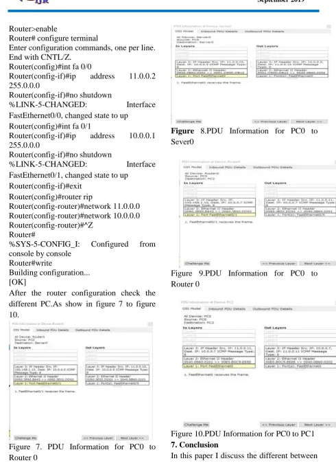
After the router configuration check the different PC.As show in figure 7 to figure 10.
Figure 7. PDU Information for PC0 to Router 0
Figure 8.PDU Information for PC0 to Sever0
Figure 9.PDU Information for PC0 to Router 0
Figure 10.PDU Information for PC0 to PC1
7. Conclusion
static NAT method is used in the NAT router writes all PC’s addressed and globally IP address. When dynamic NAT is used in the NAT router writes globally IP address rates (11.0.0.10 to 11.0.0.50). 8.
8.References
[1]. Network Address Translation (NAT) -
Router Alley.
[Online].Available:http://www.routeralley.c om/ra/docs/nat.pdf.
[2]. Introduction to Network Address Translation,
[Online].Available:http://www.cisco.com/ne tworkers/nw00/pres/2211.pdf.
[3]. Jeff Tyson, How Network Address
Translation Works
http://computer.howstuffworks.com/nat.htm [4]. Private Networks and NAT Module. [Online].
Availablehttp://www.cs.virginia.edu/~itlab/ book/slides/module17-nat.ppt.
[5].
A.S.Tanenbaum.ComputerNetworks.Prentic e-Hall,2002.
[6]. Introduction to Dynamic Routing
Protocols. [Online].