Highly Secure Strong PUF based on Nonlinearity of
MOSFET Subthreshold Operation
Mukund Kalyanaraman and Michael Orshansky
Department of Electrical and Computer Engineering
The University of Texas at Austin
email:
{
orshansky,mukundkm
}
@utexas.edu
1
Abstract
Silicon physical unclonable functions (PUFs) are security primitives relying on intrinsic randomness of IC manufacturing. Strong PUFs have a very large input-output space which is essential for secure authentication. Several proposed strong PUFs use timing races to produce a rich set of responses. However, these PUFs are vulnerable to machine-learning attacks due to linear separability of the output function resulting from the additive nature of timing delay along timing paths.
We introduce a novel strong silicon PUF based on the exponential current-voltage behavior in subthreshold region of FET operation which injects strong nonlinearity into the response of the PUF. The PUF, which we term subthreshold current array (SCA) PUF, is implemented as a two-dimensional
n×ktransistor array with all devices subject to stochastic variability operating in subthreshold region. Our PUF is fundamentally different from earlier attempts to inject nonlinearity via digital control techniques, which could also be used with SCA-PUF. Voltages produced by nominally identical arrays are compared to produce a random binary response.
SCA-PUF shows excellent security properties. The average inter-class Hamming distance, a mea-sure of uniqueness, is 50.3%. The average intra-class Hamming distance, a measure of response stability, is 0.6%. Crucially, we demonstrate that the introduced PUF is much less vulnerable to modeling at-tacks. Using a machine-learning technique of support-vector machine with radial basis function kernel for best nonlinear learnability, we observe that “information leakage” (rate of error reduction with learning) is much lower than for delay-based PUFs. Over a wide range of the number of observed challenge-response pairs, the error rate is 3−35X higher than for earlier designs.
2
Introduction
Many electronic systems require solutions for security, unique identification, and authentication. As a low cost solution, physical unclonable functions (PUFs) have been proposed [1, 2]. PUFs are pseudo-random functions that exploit the pseudo-randomness inherent in the scaled CMOS technologies to generate random output strings. In response to an input challenge a PUF generates a binary response. Because of the randomness of the input-to-output mapping, different PUFs generate a different response for the same challenge. The set of challenge-response pairs (CRPs) defines the behavior of a PUF and provides an ability to uniquely identify it.
Strong PUFs are essential for public authentication security protocols in which the number of CRPs needs to be large such that the same CRPs are not re-used for authentication (preventing the adversary from simply capturing the CRPs transmitted in plain text and using them for subsequent attacks). However, for a strong PUF to be an effective security primitive, the CRPs need to be unpredictable: given a certain set of known challenge-response pairs, it should not be possible to predict the unobserved CRPs with any reasonable probability. If that is not the case, an adversary can stage an attack based on building a model of the PUF. A number of strong PUFs have been proposed in the literature over the years. However, the unpredictability of responses in published strong PUFs has been shown to be limited. The earliest example of a strong silicon PUF is the arbiter-based PUF proposed in [1]. It exploits variation in path delays between gate stages in two parallel propagation paths to generate a binary response by using an arbiter. The arbiter-based PUF has been shown to be vulnerable to model-building attacks [11, 12]. In such attacks, machine-learning techniques, such as regression, neural networks, support vector machines, are used to construct a model of the internal parameters of a PUF based on the observed instances. Attempts to remediate this vulnerability resulted in several variants of the arbiter-based PUF [4, 5]. These approaches attempt to improve unpredictability by using digital techniques. In [8], an XOR gate is used to scramble outputs of two parallel arbiter-based PUFs. In [5], a feed-forward path is introduced within the arbiter-PUF circuit as a way to inject nonlinearity. Unfortunately, recent work [11] shows that all of the derivatives of the arbiter-based PUF are also vulnerable to model-building attacks, even though the improved versions require a larger number of observed CRPs for building a model.
In weak PUFs, the number of CRPs typically grows linearly with the PUF physical size. That implicitly means that each CRP depends on a single, and not shared, realization of a random physical property. That makes it impossible to build a model of such a PUF. Several constructions have been demonstrated. The SRAM-based PUF produces a unique chip signature by relying on threshold voltage mismatch between cell transistors which leads to a cell settling into a random state upon powering up the array [6, 7]. The ring oscillator PUF proposed in [8] generates a response based on the random frequency difference between pairs of ring oscillators.
This paper introduces a novel intrinsic strong silicon PUF based on the essential nonlinearity of terminal current-voltage behavior of field-effect transistors (FETs) at the nanometer scale. The fundamental principle is reliance on the subthreshold regime of the FET operation, where current is an exponential function of threshold voltage, which exhibits strong random intrinsic variability. An additional nonlinearity is due to the exponential dependence of threshold voltage (1) on drain-to-source voltage due to drain-induced barrier (DIBL) effect, and (2) on body-to-drain-to-source voltage due to body effect. Both of these are used to create coupling between FETs in the array, further improving nonlinearity and unpredictability. The new PUF shows excellent security properties.
3
New Source of Nonlinearity: FET Subthreshold Current
We develop a principled approach to significantly improving PUF resilience against machine-learning attacks. It has been recognized that the limitations of strong arbiter-based PUFs in terms of un-predictability are due to their linear additive dependence on partial delays in generating a response. learning methods are particularly effective in constructing models of such functions. Machine-learning algorithms for classification are tasked with classifying an object given a set of its attributes. In supervised learning setting, the algorithm is first given a set of training examples in which both the attributes and the label is available. If the space being learned is naturally linearly separable, it is easy for the learning algorithm to derive a classification rule with low prediction error.
function of the delays of individual stages, as formalized in [13]. Attempts to introduce nonlinearity in the arbiter-based PUF, such as using feed-forward paths or XORing the outputs introduce nonlinearity through digital means. Empirical results of model-building attacks show that the added nonlinearity helps but is insufficient in that low prediction errors can still be achieved. A distinct limitation of at least some digital techniques, those based on XORing outputs, is that PUF instability increases along with the improvement in unpredictability [11].
In order to aid the discussion, we introduce a formal distinction between the ways of injecting nonlinearity. For most silicon PUFs, a random bit is produced by evaluatingsgn(f(x)−f(y)), where x, y are vectors of realizations of a random physical parameter. Functionf(·) maps the underlying realizations of physical parameters, e.g. threshold voltages, to a measurable circuit-level quantity, e.g. delay or voltage. If functionf(·) is expressible entirely in terms of real-valued functions we call it a fully continuous random function (FCRF), otherwise we call it a mixed continuous-discrete random function (MCDRF). With that distinction in place, we point out that the above digital techniques of achieving nonlinearity still use delay races as a building block for PUFs with the underlying mechanism of generating pseudo-random behavior remaining linear. Thus, both the XOR PUF and the FF PUF start with a “native” FCRF-based PUF and ultimately use the mixed continuous-discrete random function to achieve nonlinearity. Given that the known digital techniques can be equally applied to other underlying (“native”) FCRF-based PUFs, the question becomes: can strong silicon PUFs utilizing fully continuous random functions be constructed that are significantly more secure than the FCRF-based delay PUF? We provide an affirmative answer in this paper.
The key for engineering a secure silicon PUF is identifying an output function that would be nonlinear in random variables. We introduce a highly unpredictable PUF that uses the strongly non-linear I-V terminal dependencies to generate PUF responses. Its central feature is that it moves away from the delay/digital implementation paradigm towards the current/analog one, thereby realizing the necessary degree of nonlinearity over a space of permutations. Because it doesn’t rely on digital techniques for injecting the nonlinearity, it does not compromise the stability in the output response to environmental variations.
The output function should ideally have two properties: (1) be nonlinear in random parameters, and (2) introduce the coupling effect in which two or more random variables interact in producing the output. Both of these properties are enabled if the binary output is produced by comparing two voltages produced by a suitably arrangednetwork of FETs operating in subthreshold region. The key to our analysis is the equation relating the subthreshold current to FET terminal voltages [14]:
Ids=IS10
Vgs−Vth(Vds,Vbs)
S (1−10
−nVds
S )
=IS10
Vgs−Vth+λVds+γVbs S (1−10
−nVds
S )
(1)
where Ids is the drain-to-source subthreshold current, IS is the nominal current, Vgs is the
gate-to-source voltage, Vthis the transistor threshold voltage, Vdsis the drain-to-source voltage, Vbsis the
body-to-source voltage, andλ,γ, andnare the coefficients of drain-induced barrier lowering and body-bias, and the subthreshold coefficient respectively. Crucially, the current is exponentially dependent on the threshold voltageVth. This is important becauseVthexhibits large and spatially-uncorrelated
variability due to random dopant fluctuation (RDF). In nanometer scale CMOS devices, RDF is very significant and grows with transistor scaling [14, 15]. Equation 1 also captures the impact of physical mechanisms of drain-induced barrier lowering and of body effect which lead to a dependence ofVthon
Vds andVbs. In the second part of the equation, we use a linear expansion ofVth in terms ofVdsand
SCA1
SCA2
0/1
C11 C12
Ckn
Comparator
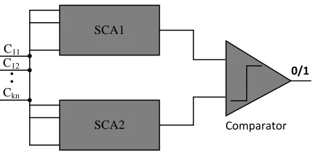
Figure 1: PUF architecture.
4
Subthreshold Current Array PUF
4.1
Array PUF Architecture
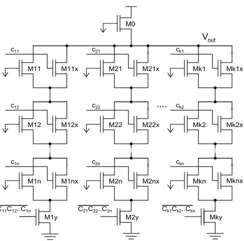
We now present a transistor-level realization of a subthreshold current array PUF (SCA-PUF) that exploits the above current behavior to construct a highly secure strong PUF. Figure 1 depicts the overall architecture of the SCA-PUF. The PUF is implemented as a two-dimensional transistor array with all devices subject to stochastic variability operating in subthreshold region. The 2D organization allows to maximize the reliability and security properties of the PUF, as demonstrated by experiments. Each PUF consists of two nominally identical arrays. The array schematic is shown in Figure 2. The array is composed ofkcolumns and nrows of a unit cell. We use the term “stochastic” transistor to refer to a device with high amount of threshold voltage variability. The unit cell consists of a stochastic subthreshold nFET, which is a transistor with a highly variable threshold voltge that always operates in the subthreshold region. A non-stochastic switch transistor is arranged in parallel to the stochastic FET. The non-stochastic transistorM0 acts as a load device and operates in the subthreshold region (its gate terminal is tied to ground). At the bottom of each column of cells is a footer transistorM iy
controlled byCi1Ci2. . . Cin. Its role is to ensure that there is never a low-impedance path to ground
fromVout.
Both array blocks are driven with the same set of control inputs and thus in the absence of variability produce identical voltages. The randomness of transistor threshold voltages leads to the differences in two output voltages. The binary response is generated by comparing the output voltages produced by the two arrays via a comparator. The size of the CRP set is 2kn, making it a strong PUF.
We now describe in greater detail the building block of the array, the unit cell. In each cell, which we identify using a column indexi and a row indexj, an NMOS transistor M ij always operates in the subthreshold region: its gate terminal is tied to ground. An NMOS transistorM ijx, in parallel withM ij, acts as a switch transistor. Careful sizing of both devices is essential for correct operation. Two requirements need to be satisfied. First, only transistorM ij is subject to significant variation of threshold voltage due to random dopant fluctuation. This is achieved by sizing tranistors M ij
to their minimum size to maximize their threshold voltage variability according to Pelgrom’s model [16]. Second, the subthreshold current through the switch transistor M ijx needs to be negligible compared to the subthreshold current through M ij. At the same time, M ijx needs to have small on-state resistance. These requirements can be met, for example, withW = 10Wmin andL= 10Lmin.
Because the nominal current IS in the subthreshold region is exponentially dependent on channel
lengthIds(M ijx)/Ids(M ij)≈0 when Cij = 0.
The role of the switch transistor is to set Vds of the stochastic transistor to zero. In this case,
M0
M11 M11x M21 M21x Mk1 Mk1x
c11 c21 ck1
M12 M12x M22 M22x Mk2 Mk2x
c12 c22 ck2
M1n M1nx M2n M2nx Mkn
c1n c2n ckn
Mknx
..
.
..
.
..
.
....
Ck1Ck2..Ckn
C21C22..C2n
C11C12..C1n
Mky M2y
M1y
Vout
Figure 2: Circuit schematic of the 2D subthreshold current array.
be ignored. Depending on the control input, the stochastic transistor therefore is either part of the pull-down network and contributes current that depends on its threshold voltage, or does not impact total current flowing through a branch. Thus, each branch can have 2n current values.
4.2
Analysis of Array Nonlinearity
The principle feature of the circuit we propose is that it has a highly nonlinear boundary between the regions of PUF 1-outputs and 0-outputs in thekn-dimensional space of Vth. In this section, we
more formally analyze the nonlinearity of the SCA-PUF. To enable analytical treatment, we derive equations for two special cases: (a) a single-column array, (b) a single-row array, and (c) a simple 2D array with k= 2 and n= 2. We aim to bring out the form of the nonlinearity involved in each of the two special cases (a) and (b). The two special cases of the 2D array exhibit distinct forms of nonlinearity which, when combined within a 2D array structure, form a rich nonlinear space.
First, we consider the single-row (parallel-only) array with two columns (n= 1,k= 2). To be able to derive a closed-form equation relatingVout to threshold voltages of two “stochastic” transistors, we
assume that Vds >100 mV. For n = 1 we can also ignore the impact of the body-bias effect. With
that, Equation 1 can be written as:
log
I
ds
IS
= Vgs−Vth+λVds
S (2)
For convenience, we use a simplified notation where Vth,M0 =V0 and similar for others. Solving
forVout, we get:
Vout=
S
1 +λ
[log(IS) +λVdd−V0−log(I0)] (3)
Applying KCL at nodeVout,I0=I11+I21, whereI11,I21are the currents throughM11 andM21,
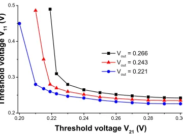
0.20 0.22 0.24 0.26 0.28 0.30 0.2 0.3 0.4 0.5 T h r e s h o l d v o l t a g e V 1 1 ( V ) V out = 0.266 V out = 0.243 V out = 0.221
Threshold voltage V 21
(V)
Figure 3: Response nonlinearity in the single-row array: nonlinearity of additive subthreshold current behavior.
0.20 0.22 0.24 0.26 0.28 0.30
0.15 0.17 0.19 0.21 0.23 0.25 0.27 0.29 0.31 T h r e s h o l d v o l t a g e V 1 2 ( V ) V out = 0.043 V out = 0.034 V out = 0.027
Threshold voltage V 11
(V)
Figure 4: Response nonlinearity in the single-column array: nonlinearity of series-connected subthreshold FETs.
Vout=
S
1 +λ
λVdd
S − V0
S −log
10−V11 +SλVout + 10
−V21 +λVout S
(4)
Equation 4 is a transcendental equation. The key to our construction is the nonlinearity ofVout in
terms of values of threshold voltages of transistorsM11 and M21. The nonlinearity of Equation 4 is explored in Figure 3.
Next we consider the single-column array (k = 1) with only two rows (n = 2). It represents a subthreshold current array with series-only “stochastic” transistorsM11 andM12. Using Equation 1 for transistorsM0,M11 andM12 respectively, and treating the source (drain) ofM11 (M12) as an intermediate nodeVx, we get:
log
I0
IS
=−Vout(1 +λ)−V0+λVdd
S +log
1−10
−nVdd+nVout S (5) log I 11 IS
= −Vx(1 +λ)−V11+λVout
S +log
1−10−nVoutS+nVx
(6) log I 12 IS
= −V12+λVx
S +log
1−10−nVxS
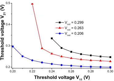
0.20 0.22 0.24 0.26 0.28 0.30 0.2 0.3 0.4 0.5 T h r e s h o l d v o l t a g e V 2 1 ( V ) V out = 0.299 V out = 0.263 V out = 0.206
Threshold voltage V 11
(V)
Figure 5: Response nonlinearity in the2×2SCA.
We also know thatI0=I11=I12. Unfortunately, expressingVoutin closed form appears infeasible.
By simultaneously solving the system of Equations 5, 6 and 7 numerically, we generate Figure 4 and observe the nonlinearity of the single-column (series-only) array topology. The nonlinearity is significant. Notably, while the nonlinear separating surface of the parallel-only array is convex, the surface separating 0- and 1-regions in the series-only array is concave.
Finally, we consider the 2×2 array. We treat the source (drain) of M11 (M12) as nodeVx and
source (drain) ofM21 (M22) as nodeVy. Using Equation 1 for transistorsM0-M22, we get:
log
I
0
IS
=−Vout(1 +λ)−V0+λVdd
S +log
1−10−nVddS+nVout
(8) log I 11 IS
= −Vx(1 +λ)−V11+λVout
S +log
1−10−nVoutS+nVx
(9) log I 21 IS
= −V21+λVx
S +log
1−10−nVxS
(10) log I 12 IS
= −Vy(1 +λ)−V12+λVout
S +log
1−10
−nVout+nVy S (11) log I 22 IS
=−V22+λVy
S +log
1−10
−nVy S
(12)
Additionally, we have I11 =I21 andI12 =I22, and I0 =I11+I12. Simultaneously solving these
equations, along with the system of Equations 8-12, using a numerical package, we show the resulting nonlinearity of Vout in Figure 5. In the next section we show that the effect of the created strong
nonlinearities is a PUF whose input-ouput behavior is difficult to model through observation of a partial list of CRPs.
5
Analysis of PUF Security Properties via Transistor-Level
Simulations
The performance of the proposed SCA-PUF was simulated using SPICE, the industry-standard transistor-level circuit simulator, in a 45 nm technology node using the predictive technology models [17–19]. The source of randomness is inVth variability assumed to be caused by random dopant fluctuation
distribution with a standard deviation of 40 mV, a value consistent with ITRS data [20]. The results are based on the output random string generated by the PUF having the length of 128 bits.
0.0 0.2 0.4 0.6 0.8 1.0
0.0 0.1 0.2 0.3 0.4 0.5 0.6 F r e q u e n c y o f o c c u r a n c e
Hamming distance (normalized) Intra-class Inter-class
(a) Single-row (parallel-only) array
0.0 0.2 0.4 0.6 0.8 1.0
0.00 0.01 0.02 0.03 0.04 0.05 0.06 0.07 F r e q u e n c y o f o c c u r a n c e
Hamming distance (normalized) Intra-class Inter-class
(b) Single-column (series-only) array
0.0 0.2 0.4 0.6 0.8 1.0
0.0 0.2 0.4 F r e q u e n c y o f o c c u r a n c e
Hamming distance (normalized) Intra-class Inter-class
(c) Square 2D array
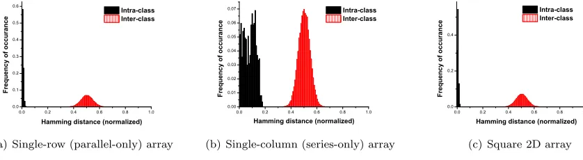
Figure 6: Inter-class and intra-class HD for three array topologies.
There are several commonly used metrics that quantify the goodness of a PUF [21]. The inter-class Hamming distance (HD) is a measure of the ability to differentiate two different PUFs under the same input. Ideally, each PUF produces an entirely unique response, and thus the ideal inter-class HD normalized to the total number of bits in the output is 0.5. Intra-class HD is the measure of the reliability of a PUF and quantifies how much response of a given PUF changes under a different set of environmental conditions. Ideally, the intra-class HD is 0. Reliability of the PUF responses across different environmental conditions was studied for supply voltage variation of 5% and temperature ranging from−40◦C to 85◦C. Monte-Carlo simulation sample size used to extract inter-class HD was 1000.
The previous section has shown that the nonlinear behavior implemented in the 2D subthreshold current array is a combination of the nonlinearities of the single-row array which represents a parallel-only combination of stochastic subthreshold FETs, and the single-column array which represents a series-only combination of stochastic subthreshold FETs. The series-only and the parallel-only com-binations lead to different types of nonlinearities. In principle, the SCA-PUF can be implemented via a variety of n×k array dimensions. For example, a PUF with the same CRP space of 2nk can be implemented as eithern×kornk×1 or 1×nkarray. The latter two types would correspond to the parallel-only and series-only combinations. Therefore, it is important to investigate the behavior of different possible array organizations with respect to PUF security and reliability metrics.
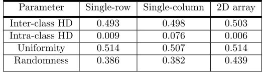
Figure 6 shows the histograms of the normalized intra-class and inter-class HDs. The mean values are summarized in Table 1. We observe that the mean inter-class HD for all three cases is excellent and is practically indistinguishable from 0.5. Intra-class HD is excellent for a parallel-only array but is noticeably higher for the series-only array. Interestingly, when the two types of nonlinearity are combined within the 2D array, intra-class HD is still excellent (below 0.01).
Another useful measure of the goodness of a PUF is the uniformity metric defined by [21]. In an ideal PUF, the fraction of challenges that produces a response of 1 and of 0 should be equal. A useful, and closely, related metric is randomness, as defined by [22], which also quantifies uniformity but in a min-entropy sense. The histograms of the uniformity metric are shown in Figure 7. For comparison, Table 2 summarizes the figures of merit for several published PUFs.
0.0 0.2 0.4 0.6 0.8 1.0 0.00 0.01 0.02 0.03 0.04 0.05 0.06 0.07 0.08 0.09 0.10 F r e q u e n c y o f o c c u r a n c e Uniformity
(a) Single-row (parallel-only) array
0.0 0.2 0.4 0.6 0.8 1.0
0.00 0.01 0.02 0.03 0.04 0.05 0.06 0.07 0.08 0.09 0.10 F r e q u e n c y o f o c c u r a n c e Uniformity
(b) Single-column (series-only) array
0.0 0.2 0.4 0.6 0.8 1.0
0.00 0.01 0.02 0.03 0.04 0.05 0.06 0.07 0.08 0.09 0.10 F r e q u e n c y o f o c c u r a n c e Uniformity
(c) Square 2D array
Figure 7: Distribution of the uniformity metric for three array topologies.
Table 1: Average inter-class and intra-class Hamming distance, uniformity, and randomness for σVos = 7
mV.
Parameter Single-row Single-column 2D array
Inter-class HD 0.493 0.498 0.503
Intra-class HD 0.009 0.076 0.006
Uniformity 0.514 0.507 0.514
Randomness 0.386 0.382 0.439
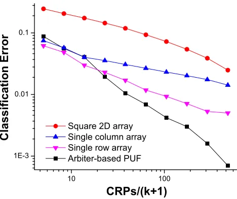
the non-training challenge inputs and the prediction error rateis measured. The procedure is carried out for several training sample sets of different size. Figures 8 and 9 show the comparison of prediction error vs. training set size for 8 bit and 16 bit PUFs respectively. To maximize the learning ability of the SVM algorithm, we employed a nonlinear radial basis function (RBF) kernel. Using a nonlin-ear kernel makes SVM more effective in nonlinnonlin-ear classification problems. We further used a 5-fold cross-validation scheme to select the best kernel parameters. The results indicate that the SCA-PUF is significantly more secure than the delay based PUF. The prediction error is almost an order of magnitude higher than for the arbiter PUF. As we argued earlier, the digital techniques of injecting nonlinearity can be thought of as qualitatively distinct from the behavior of the “native” PUF. For that reason we focus on comparing SCA-PUF behavior to the arbiter PUF learning behavior only. We again note that digital control techniques could also be applied to SCA-PUF, and would further enhance its native nonlinearity and security.
Another practical aspect that we investigate is the influence of comparator characteristics on the overall PUF behavior. The voltage difference|∆V|between the two outputs depends on the realizations of random threshold voltages. In an ideal comparator, the binary output matches perfectly the sign of|∆V| at any magnitude. In practice, we need to take into account the effect of comparator offset voltage. Offset voltage effectively determines the resolution of the comparator and it may also impact the security properties of the SCA-PUF. We first investigate the distribution of the actual observed voltage differences that the comparator needs to resolve. The mean|∆V| is 14.3 mV, 48.5 mV and 14.5 mV respectively for the parallel-only, series-only, and 2D array SCA-PUFs. Figure 10 shows the lower tail of the cumulative distribution of|∆V|for three array topologies.
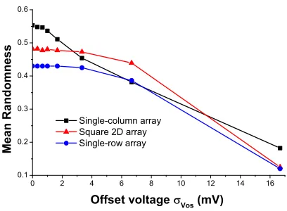
We study the impact of offset voltage on PUFs properties by assuming it follows a normal distribu-tion with a mean of 0 mV and a standard deviadistribu-tion of several mVs. Figures 11 and 12 show the effect of offset voltage on intra-class Hamming distance and on the randomness measure. The inter-class Hamming distance was found to remain nearly-constant around 0.5 for all three circuit constructs. Based on this exploration, we find that a comparator that has an offset voltage of up to σV os = 7
1 10 0.01
0.1
C
l
a
s
s
i
f
i
c
a
t
i
o
n
E
r
r
o
r
CRPs/(k+1) Single column array 2D array (k=2, n=4) Single row array Arbiter-based PUF
Figure 8: Classification error from modeling an 8-bit PUF via an SVM-based attack.
10 100
1E-3 0.01 0.1
C
l
a
s
s
i
f
i
c
a
t
i
o
n
E
r
r
o
r
CRPs/(k+1) Square 2D array Single column array Single row array Arbiter-based PUF
10µ 100µ 1m 10m 100m 1 1E-4
1E-3 0.01 0.1 1
| V| (V)
c
d
f
(
|
V
|
)
Single-column array Single-row array Square 2D array
Figure 10: Cumulative distribution of|∆V|for three array topologies.
0 2 4 6 8 10 12 14 16
0.5 0.6 0.7 0.8 0.9 1.0
I
n
t
r
a
-c
l
a
s
s
H
D
Single-row array Single-column array Square 2D array
Offset voltage Vos
(mV)
7.0 7.2 7.4 7.6 7.8 8.0
I
n
t
r
a
-c
l
a
s
s
H
D
Figure 11: Dependence of intra-class HD on offset voltage spread.
0 2 4 6 8 10 12 14 16
0.1 0.2 0.3 0.4 0.5 0.6
M
e
a
n
R
a
n
d
o
m
n
e
s
s
Single-column array Square 2D array Single-row array
Offset voltage Vos
(mV)
Table 2: Average intra-class and inter-class HD for PUFs reported in the literature [23].
PUF type Inter HD (%) Intra HD (%)
Optical PUF 49.79 25.25
Coating PUF ≈50 <5
Basic arbiter PUF 23 <5
Feed-forward arbiter PUF 38 9.8
Basic Ring Oscillator PUF ≈1 ≈0.01
Ring Oscillator PUF w/comparator 46.14 0.48
SRAM PUF 49.97 <12
Latch PUF 50.55 3.04
Butterfly PUF ≈50 <6
Sense Amplifier PUF 50.00 6
in [25]. Achieving the offset standard deviation of about 7 mV will require either sizing the active devices of the sense amplifier to about 100Xof the minimum transistor size or using offset cancellation techniques, both of which are easily realizable.
6
Conclusion
We introduced a novel strong silicon PUF based on the essential nonlinearity of responses produced by the physics of field-effect transistors (FETs) at the nanometer scale. The PUF shows excellent security properties which are superior to those reported for other strong PUFs. We demonstrate that the introduced PUF is less vulnerable to modeling attacks and that its “information leakage” is significantly lower than for delay-based strong PUFs.
References
[1] B. Gassend, D. Clarke, M. van Dijk, and S. Devadas. Silicon Physical Random functions. In ACM Conference on Computer and Communications Security, pages 148–160, New York, NY, USA, 2002. ACM Press.
[2] J. W. Lee, D. Lim, B. Gassend, G. E. Suh, M. van Dijk, and S. Devadas. A technique to build a secret key in Integrated circuits for Identification and Authentication application. InProceedings of the Symposium on VLSI Circuits, pages 159–176, 2004.
[3] K. Lofstrom, W.R. Daasch, and D. Taylor. IC Identification Circuit using Device mismatch. In Proceedings of ISSCC 2000, pages 372–373, 2000.
[4] M. Majzoobi, F. Koushanfar, and M. Potkonjak. Lightweight secure PUFs. In ICCAD ’08: Proceedings of the 2008 IEEE/ACM International Conference on Computer-Aided Design, pages 670–673, Piscataway, NJ, USA, 2008. IEEE Press.
[5] B. Gassend, D. Lim, D. Clarke, M. van Dijk, and S. Devadas. Identification and authentication of Integrated circuits: Research articles. Concurr. Comput. : Pract. Exper., 16(11):1077–1098, 2004.
[7] J. Guajardo, S.S. Kumar, G.J. Schrijen, and P. Tuyls. FPGA intrinsic PUFs and their use for IP protection. InCryptographic Hardware and Embedded Systems Workshop, volume 4727 ofLNCS, pages 63–80, September 2007.
[8] E.S. Suh and S. Devadas. Physical Unclonable Functions for device authentication and secret key generation. InDesign Automation Conference, pages 9–14. ACM Press, 2007.
[9] S.S. Kumar, J. Guajardo, R. Maes, G.-J. Schrijen, and P. Tuyls. The butterfly PUF protecting ip on every FPGA. InHardware-Oriented Security and Trust, 2008. HOST 2008. IEEE International Workshop on, pages 67–70, June 2008.
[10] J. Guajardo, S.S. Kumar, K. Kursawe, G.J. Schrijen, and P. Tuyls. Intrinsic Physical Unclonable Functions in Field Programmable Gate Arrays. ISSE/SECURE 2007:, pages 1–10, 2007.
[11] U. R¨uhrmair, F. Sehnke, J. S¨olter, G. Dror, S. Devadas, and J. Schmidhuber. Modeling attacks on physical unclonable functions. In CCS 2010: Proceedings of the 17th ACM conference on Computer and communications security, pages 237–249, New York, NY, USA, 2010. ACM.
[12] M. Majzoobi, F. Koushanfar, and M. Potkonjak. Testing Techniques for Hardware Security.2008 IEEE International Test Conference, pages 1–10, October 2008.
[13] L. Daihyun. Extracting Secret Keys from Integrated Circuits. Master’s thesis, MIT, USA, 2004.
[14] T. Yuan, D.A. Buchanan, C. Wei, D.J. Frank, K.E. Ismail, L. Shih-Hsien, G.A. Sai-Halasz, R.G. Viswanathan, H.-J.C. Wann, S.J. Wind, and H.-S Wong. CMOS scaling into the nanometer regime. Proceedings of the IEEE, 85(4):486–504, April 1997.
[15] M. Orshansky, S. Nassif, and D. Boning. Design for Manufacturability And Statistical Design: A Constructive Approach. Springer, 2007.
[16] M.J.M. Pelgrom, A.C.J. Duinmaijer, and A.P.G. Welbers. Matching Properties of MOS Transis-tors. IEEE Journal of Solid-State Circuits, 24(5):1433 – 1439, October 1989.
[17] W. Zhao and Y. Cao. New Generation of Predictive Technology Model for Sub-45nm Design Exploration. Electronic Design, pages 7–12, 2006.
[18] Y. Cao, T. Sato, M. Orshansky, D. Sylvester, and C. Hu. New Paradigm of Predictive MOSFET and Interconnect Modeling for Early Circuit Simulation. Methodology, pages 201–204, 2000.
[19] Y. Cao. Predictive Technology Model. Internet: http://ptm.asu.edu/.
[20] ITRS. International Technology Roadmap for Semiconductors. Internet: http://public.itrs.net.
[21] A. Maiti, V. Gunreddy, and P. Schaumont. A systematic method to evaluate and compare the performance of Physical Unclonable Functions. Cryptology ePrint Archive, Report 2011/657, 2011. http://eprint.iacr.org/.
[22] Y. Hori, T. Yoshida, T. Katashita, and A. Satoh. Quantitative and Statistical Performance Evaluation of Arbiter Physical Unclonable Functions on FPGAs. International Conference on Reconfigurable Computing and FPGAs, pages 298–303, December 2010.
[23] A.-R. Sadeghi and D. Naccache.Towards Hardware-Intrinsic Security: Foundations and Practice. Springer, 2010.
[24] C.C. Chang and C.J. Lin. LIBSVM: A library for support vector machines. ACM Transactions
on Intelligent Systems and Technology, 2:27:1–27:27, 2011. Software available at http://www.
csie.ntu.edu.tw/~cjlin/libsvm.
![Table 2: Average intra-class and inter-class HD for PUFs reported in the literature [23].](https://thumb-us.123doks.com/thumbv2/123dok_us/7888082.1308882/12.612.146.465.106.252/table-average-intra-class-inter-class-reported-literature.webp)
