Design Of Mobility Robust Tree Construction
Framework For Zigbee Wireless Networks.
Chaitali G.Golhar, Prof.A.W.Motikar Digital Electronics,Amaravati university,Yavatmal,India
Abstract— With the increasing sophistication of wireless communications and sensing technologies, various sensor-based applications, such as tour guiding and industrial automation, generate tremendous economic and social benefits. The potential for even greater impact has motivated extensive studies on wireless sensor networks (WSNs) in recent years. Zigbee is the key of interest for number of researchers. ZigBee is a specification formalized by the IEEE802.15.4 standard for low-power, low-cost, low-data-rate wireless personal area networks. In ZigBee networks, a tree topology is often used to construct a wireless sensor network for data delivery applications. However, delivery failures constantly occur in ZigBee wireless applications due to node movements and network topology changes. To increase the data delivery ratio and mitigate the effects of packet loss caused by the node mobility, it is necessary to deploy the router and construct cluster tree topology. We present details of the proposed algorithms for node deployment and tree construction in the framework. The effectiveness of network topologies constructed under the framework is demonstrated through comprehensive ns-2 simulations
Index Terms—Mobility robustness, tree topologies, ZigBee wireless networks.
I.INTRODUCTION
Many ZigBee applications, such as tour guiding and indoor/building monitoring systems, require moving objects to be equipped with an end device that is connected to a backbone network for data collection and dissemination . Another category of applications use ZigBee routers as roadside units and end devices as in-vehicle units. In such applications, ZigBee cluster-tree networks can serve as vehicle-to infrastructure communications in vehicular ad hoc networks (VANETs)[12], because ZigBee can provide low power consumption, medium data rates, and reliable communications .Normally, routers that are connected to the backbone network are static and equipped with reliable power supplies, whereas mobile end devices rely on batteries. In many applications such as drivers who receive traffic information from ITSs, tourists who receive recreational information, and workers who receive supervisory messages, the major function of mobile end devices is to receive data from the network coordinator rather than send data through the network. the ZigBee specification allows a small and simple protocol stack and, thus, has lower implementation cost compared with Bluetooth and Wi-Fi. The much lower power consumption of ZigBee, compared with Wi-Fi [1], also facilitates a long lifetime of mobile end devices, which greatly benefits the aforementioned applications.
To improve the downlink data delivery ratio, we propose an approach that exploits the aforementioned
information to optimize the locations of routers and construct a mobility robust tree topology in a ZigBee wireless network. The approach deploys routers and constructs a topology with the property that mobile nodes will move along the constructed data-forwarding path with high probability. Data will reach the target mobile nodes as long as they are within the transmission range of any router on the forwarding path. In other words, we choose the positions of the routers and design the tree topology so that most movements are directed toward the root of the tree. To achieve our objective, we gather information about node movements in the environment and construct a ZigBee tree topology framework. In particular, the framework considers the regularity of the mobility patterns during the construction of the tree and deployment of the routing nodes, and it incorporates an overhearing mechanism for mobile nodes to further improve the data delivery ratio. We also design heuristic and low-complexity algorithms for node deployment and tree construction and analyze their performance in ZigBee networks. The effectiveness of network topologies that consider mobility regularity is demonstrated through the ns-2 network simulator.
II.RELATED WORK
In this section, we discuss mobility mechanisms and explain the difficulties that arise in the direct application of existing mobility patterns to a ZigBee network. We also consider studies of mobility support in WSN. Author T.Camp, in reference[2],showed that there are two types of mobility models used in the simulation of networks: traces and synthetic models. Traces are those mobility patterns that are observed in real life systems. Traces provide accurate information, especially when they involve a large number of participants and an appropriately long observation period. However, new network environments (e.g. ad hoc networks) are not easily modeled if traces have not yet been created. In this type of situation it is necessary to use synthetic models. Synthetic models attempt to realistically represent the behaviors of MNs without the use of traces. Different synthetic entity mobility models for ad hoc networks:
1. Random Walk Mobility Model (including its many derivatives): A simple mobility model based on random directions and speeds.
2. Random Waypoint Mobility Model: A model that includes pause times between changes in destination and speed.
3. Random Direction Mobility Model: A model that forces MNs to travel to the edge of the simulation area before changing direction and speed.
1.Pursue Mobility Model: A group mobility model where a set of MNs follow a given target.
2. Reference Point Group Mobility Model: A group mobility model where group movements are based upon the path traveled by a logical center.
In reference [3],Author J.Ghosh proposes socially aware routing based on the property that mobile nodes usually move among a small set of socially significant points (hubs). The routing scheme tends to forward messages toward one of the hubs the recipient visits with high frequency. Main contribution of his work is a routing protocol called as ‘Sociological Orbit Aware Location Approximation And Routing (SOLAR-HUB),user level routing protocol based on k-shortest path (ksp) called static SOLAR-KSP and dynamic SOLAR-KSP. In reference [13],K.Akkya has given the classification of protocols as 1.Data centric 2.Hierarchical and 3.Location based.
Chalermern, in reference[14], studied on “Directrd diffusion”for wireless sensor network.“Directrd diffusion” is a data centric in that all the communication is for named data. All the nodes in a directed diffusion based network are application aware. It consists of different elements-1.Interest-A query which specifies what user wants. 2.Data-event and 3.Gradient-Directed state created in each node that receives an interst. The drawback of this method is that reinforcement scheme allows the node of a failed link to participate in the recovery which is unwanted.The authors F.Salvia & R.Pazzi in reference[11],proposed that if a node finds the link to the parent is broken, it broadcasts a message to find a neighboring node with the shortest path to the coordinator and adopts that node as its new parent. The drawback of this scheme is that it may cause loops in the repaired network topology. Aiso this scheme increases communication overhead and delay.
In reference [4],Author H.Lee introduces a routing scheme called “data stashing” to minimize energy consumption and network congestion by exploiting knowledge about the mobility of the mobile sinks. Instead of directly sending data from a sensor to the sink, the data are sent to certain relay nodes located on the trajectories of the sink. The trajectory of the sink is either announced by the sink itself or predicted based on the observed mobility regularity of the sinks. As sinks traverse these relay nodes, the relay nodes then send the data directly to the sinks. Long and unsteady data delivery delay is the drawback of this method.Author Chen[9] showed that, even if both the end device and the router are mobile, a cluster tree performs better than a mesh structure does when the end device is receiving data. In reference[13],if the central server cannot locate a certain mobile end device, during the procedure, the central server simply floods the whole network with messages to locate the displaced end device. However, flooding the network is costly in terms of resources, and during the procedure, the network cannot accommodate multiple instances of rapid node mobility .The drawbacks of flooding are-Implosion:-caused by duplicated message sent to same node. And Overlap When two nodes sensing the same region and send similar packets to the same neighbour.
A well-calibrated deployment should reduce the cost of network, improve the energy efficiency of n/w, have maximum Coverage and Connectivity. In reference[5],Tian and Georganas proposed a node-scheduling scheme that tries to reduce a system’s energy consumption and thereby increase the system’s lifetime. In wireless sensor networks, turning off some nodes does not affect the overall system function as long as there are enough working nodes to assure it. Therefore if we can schedule sensors to work alternatively, the system lifetime can be prolonged correspondingly. They presented a novel node scheduling scheme which is used to schedule sensors . They implement proposed scheme in NS-2 as an extension of LEACH protocol .In LEACH, operation is divided in to two rounds-1.Cluster set up phase- In which clusters are formed.2.Steady state phase-In which sensors collect data from the environment and transfer data to the cluster head and then to the base station.
Dhillon and Chakrabarty in reference [6], proposed two algorithms to support distributed applications for efficient deployment. The algorithms try to optimize the number of sensors and determine their locations. Author Chung in reference[7], proposed an approach to construct mobility-robust tree topologies in Zigbee wireless networks. The goal was to construct a topology so that mobile nodes move into its data forwarding path with high probability. The mobile nodes can receive data as long as they are located within the transmission range of any one of the routers on the forwarding path. To achieve this goal, he gather movement information on the environment and introduce the mobility-robustness of a tree topology with respect to the moving tendency of nodes. Tree construction was formulated as a graph optimization problem, and he proposed an efficient algorithm for effective tree construction.
Chakrabarty[16] formulate the sensor field as a 2-D or 3-2-D grid of coordinates and utilized the integer linear programming to determine the minimum number of sensors needed to cover the sensor field of interest. In this paper, we focus on solving the mobility problem of data delivery in ZigBee networks while attempting to minimize the network overhead
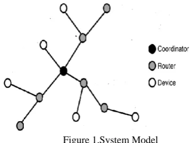
Figure 1.System Model
we present the algorithm for deployment of mobility aware ZigBee cluster tree topology (MAZCT) and define the algorithm which is implemented in following three phases.
1) node deployment(ND) phase; 2) coordinator decision(CD) phase; and 3) tree construction(TC) phase.
Also the proposed framework is used to deploy routers in a real-world indoor scenario .We use the ns-2 simulator, with the parameter settings specified in the ZigBee standard [10], to evaluate the performance of the proposed approach.
1.ND Phase
We use a simple example to elaborate the algorithm. Fig. 2. depicts a simple exemplary environment. First, our framework requires the end device’s historical movement data to be mapped on the grids. As shown in Fig. 2, each grid point represents a candidate deployment point of the routers. For simplicity, instead of showing the exact value of movement counts, we use the arrow representation in this example. The red wide arrow represents a large number of movement counts, the blue narrow arrow represents a medium number of movement counts, and no arrow means a small or even zero number of movement counts. At this stage, routers are to be deployed based on the principle of pursuing more movements that are covered under a single router. Fig. 3 shows two possible deployments for covering a movement pattern. The deployment in Fig. 3(a) is preferred, because a single router covers most movements instead of multiple routers in Fig. 3(b). The ND algorithm first finds an edge with the maximum weight. Then, starting from that edge, the ND algorithm tries to include more edges with as larger weights as possible on the constraint that those edges need to be covered by only one router. Those edges will decide one router’s position, and the ND algorithm repeats the routine until the whole environment has been covered by the routers. Finally, the deployment of routers can be completed by the ND algorithm in Fig. 4
Fig.2 Example environment.
Fig.3. Router deployments to cover the movement pattern.
Fig. 4. Deployment of routers to cover the whole environment
Algorithm1:ND
As previously mentioned, We model the transition probability matrix (mobility profile) as a directed edge-weight function on the virtual grid.
Step1:Consider a ZigBee network as Gr = (Vr,Er), where Vr is a set of immobile nodes, and Er is a set of transmission links in the network.
Step2:Let R be the empty set and Q is the set of weights on all the edges in E.
Step3:Sort Q in nonincreasing order such that the first element in Q is themaximum weight in Q with function Sort.
Step4: Denote e as the edge with the maximum weight in Q.
Step5: Dequeue the edge e(a,b) from Q, and add it into an empty set R.
Step7: Check if edges can be covered by the average communication range of one router i.e; check if the edge e(u,v) in Q and the edges in set R can be covered by a single disk with a radius that is equal to the average of the router’s communication range according to the antenna gain profile with function DiskCover.
Step8: If the edge e(u,v) and the edges in set R can be covered by a single disk, then add the edge e(u,v) to set R.
Step9: After the iteration, no more edges can be added to R under the restriction that the edges are covered by one disk with a radius equal to the average communication range of one router. And decide the router’s location as the center of the disk. Step10: To decide the angle of the antenna on this
router,calculate the sum of edge weight under the router’s coverage for each possible angle.Choose the angle with the maximum sum of edge weights to be rant (the angle of the antenna for this router) based on the design rationale where most of the node movement will be covered by a single router with function FindMaxAngle.
Step11: Keep locating more routers until Q is empty. This step ensures that the map is fully covered by the routers’ communication range.
Step12: Choose the location and the antenna angle with the sum of weights as large as possible with function FindMaxPolygonCover.
Step13: With the function MakePolygon, consider, the center of each disk as a vertex and then add the vertex to Vr.
Step14: Form bidirectional edges between each pair of two vertices in Vr with function MakeConnection.
2.CD Phase
The weight on each edge represents the end-device movement counts from one router’s coverage area to another router’s coverage area. We intend to choose a router with the maximum sum of in-edge weights as the coordinator. For example, in Fig. 5, the sum of in-edge weights (180 + 4 + 7 = 191) for router 4 is larger than that (8 + 6 + 27 = 41) for router 8. Thus, we will choose router 4 as the coordinator, given these two routers. The CD algorithm calculates each router’s sum of in-edge weights and chooses the router with the maximum sum of in-edge weights as the coordinator.
Fig.5. In- and out-edge weights for routers 4 and 8.
Algorithm2:CD
Step1:Consider a ZigBee network as Gr = (Vr,Er), grid graph G = (V,E) and the mobility profile M. Step2: Define the edge-weight function Wr by merging
states in the mobile profile M with function CombineState. (Each state in M has a corresponding vertex in G. Some states are merged into one state if the positions of their corresponding vertices in G are covered by one disk centered at a vertex in Gr.)
Step3: With function FindMax,find the vertex with the maximum sum of in-edges weight and assign that vertex as the root.
3.TC Phase
Recall that, for the tree construction, our design rationale is to prefer that the paths of downlink data delivery and end device movement patterns are as close as possible and in reverse direction. To achieve this goal for the simple example, the TC algorithm constructs the ZigBee routing tree that includes only the coordinator at first. The edge with the maximum weight among all edges directed at the coordinator will then be selected to be included as part of the tree. Then, the edge with the maximum weight among all remaining edges directed at the tree will be chosen to be included, and so on, until all routers are connected by the tree, as shown in Fig. 6.We can observe in Figs. 6 and 7. that the tree has the tendency to “grow” along the end-device movement paths (the arrows), and the directions of downlink data delivery and end device movement paths tend to be close and in reverse direction.
Fig.6. Final deployment and tree topology.
Algorithm3:TC
Step1:Consider a ZigBee network as Gr =(Vr,Er) with an edge weight function Wr that represents the movement tendency of mobile end devices. Also assign a vertex as the root and T be the Zigbee routing tree.
Step2: Define a tree T = (VT ,ET) whose root node is pr
Step3:. Construct the tree in the loop until the number of vertices in Gr is equal to that in T.
Step4: Sort Q in nonincreasing order such that the first element in Q is the edgewith largest weight with function Sort.
Step5: Add the edge with the largest weights in Q to T. Step6: Add the edge with second largest weights in Q to
T and so on.
Step7: Finally, the algorithm outputs the tree T.
IV.RESULTS AND OBSERVATIONS
To evaluate the aforementioned routing approaches, we utilize the following four performance metrics (on y-axis):
1) Packet delivery ratio; 2) One-way delay; 3) Routing overhead.
The packet delivery ratio is the ratio of the number of data packets that were successfully delivered to mobile end devices over the number of data packets that should be delivered. The one-way delay is the average time that a packet from the coordinator takes to travel to the target mobile end device. The routing overhead is the ratio of the number of packets used to exchange routing information to the total number of packets in the network. We measure the variations of the performance metrics against the mobility regularity(on x-axis). Mobility regularity is defined as the probability that a mobile end device will continue on the recommended path when it encounters a path intersection.
In this section, we present the results of the simulations. The abbreviations for the routing tree and routing mechanisms are given as follows: 1) MAZCT, the tree that is generated by our framework and 2) adhoc routing with the ZigBee specification (Ad Hoc).
We consider a scenario in an indoor environment (the D.B.N.C.O.E.T. Conference Hall). The tree topologies discussed in this case are the MAZCT determined by our framework for multiple recommended touring paths and the AdHoc.
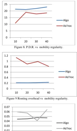
Fig.8. shows graph of packet delivery ratio vs mobility regularity. It is observed that MAZCT algorithm achives higher packet delivery ratio than Adhoc algorithm.
Our result in Fig 9shows that MAZCT achieves lower routing overhead. And the graph of delay vs mobility regularity in Fig 10 shows that MAZCT requires less delay as compaired to Adhoc one.
Figure 8. P.D.R. vs mobility regularity.
Figure 9 Routing overhead vs mobility regularity.
Figure 10 Delay vs mobility regularity.
V.CONCLUSION
In this paper, we have proposed a scheme that exploits the regularity to improve the data delivery ratio in ZigBee WSNs. The scheme deploys the network nodes and constructs the tree topology by using the mobility regularity imposed by the physical environment. In a ZigBee network, packets are forwarded to mobile end devices through routers. The primary objective of the proposed approach is to deploy the routers and construct a tree topology that enables mobile end devices to move with high probability in the direction of the routing paths. The proposed ZigBee routing tree topology deployment and construction framework incorporates the mobility information, and algorithms are developed to implement the framework. Compared to existing approaches, our framework achieves higher data delivery ratios and much lower routing overhead.
0 5 10 15 20 25
10 20 30 40
Algo Ad hoc
0 0.2 0.4 0.6 0.8 1 1.2
10 20 30 40
Algo Ad hoc
0 0.01 0.02 0.03 0.04 0.05 0.06 0.07
10 20 30 40
REFERENCES
[1] J.-S. Lee, Y.-W. Su, and C.-C. Shen, “A comparative study of wireless protocols: Bluetooth, UWB, ZigBee, and Wi-Fi,” in Proc.
IEEE IECON, 2007, pp. 46–51.
[2] T. Camp, J. Boleng, and V. Davies, “A survey of mobility models for adhoc network research,” Wireless Commun. Mobile Comput., vol. 2, no. 5,pp. 483–502, Aug. 2002.
[3] J. Ghosh, H. Q. Ngo, and C. Qiao, “Mobility profile based routing within intermittently connected mobile ad hoc networks (ICMAN),”
in Proc.IWCMC, 2006, pp. 551–556.
[4] H. Lee, M.Wicke, B. Kusy, and O. G. L. Guibas, “Data stashing: Energyefficient information delivery to mobile sinks through trajectory prediction,” in Proc. ACM/IEEE IPSN, 2010, pp. 291–302. [5] D. Tian and N. Georganas, “A coverage-preserving node scheduling scheme for large wireless sensor networks,” in Proc. ACM WSNA, 2002, pp. 32–41.
[6] S. Dhillon and K. Chakrabarty, “Sensor placement for effective coverage and surveillance in distributed sensor networks,” in Proc.
IEEE WCNC, 2003, pp. 1609–1614.
[7] W. Chung, P. Hsiu, Y. Shih, A. Pang, Y. Huang, and K. Hung, “Mobilityrobust tree construction in ZigBee wireless networks,” in
Proc. IEEE ICC, 2011, pp. 1–6.
[8] I. Akyildiz, W. Su, Y. Sankarasubramaniam, and E. Cayirci, “A survey on sensor networks,” IEEE Commun. Mag., vol. 40, no. 8, pp.
102–114, Aug. 2002.
[9] L. Chen, T. Sun, and N. Liang, “An evaluation study of mobility support in ZigBee networks,” J. Signal Process. Syst., vol. 59, no. 1, pp. 111–122, Apr. 2010.
[10] Z. Alliance, ZigBee Specifications 2006. [Online]. Available: http://www. zigbee.org/
[11] Y. Fan, J. Zhang, and X. Shen, “Mobility-aware multipath forwarding scheme for wireless mesh networks,” in Proc. IEEE
WCNC, 2008, pp. 2337–2342.
[12] J. LeBrun, C.-N. Chuah, D. Ghosal, and M. Zhang, “Knowledge-based opportunistic forwarding in vehicular wireless ad hoc networks,” in Proc. IEEE VTC, 2005, vol. 4, pp. 2289–2293. [13] K. Akkaya and M. Younis, “A survey on routing protocols for
wireless sensor networks,” Ad Hoc Netw., vol. 3, no. 3, pp. 325–349, May 2005.
[14] C. Intanagonwiwat, R. Govindan, D. Estrin, J. Heidemann, and F. Silva, “Directed diffusion for wireless sensor networking,”
IEEE/ACM Trans. Netw., vol. 11, no. 1, pp. 2–16, Feb. 2003.
[15] A. Boukerche, R. Pazzi, and R. Araujo, “A fast and reliable protocol for wireless sensor networks in critical conditions monitoring applications,” in Proc. MSWiM, 2004, pp. 157–164.
[16] K. Chakrabarty, S. Iyengar, H. Qi, and E. Cho, “Grid coverage for surveillance and target location in distributed sensor networks,”