Decentralized Control Method for Load
Sharing and Circulating Current
Minimization in Stand-alone DC Microgrid
Jeneena Babu1, Bobin K Mathew2
M.Tech Student, Dept. of EEE, Amal Jyothi College of Engineering, Kanjirapally, Kottayam, Kerala, India1
Assistant Professor, Dept. of EEE, Amal Jyothi College of Engineering, Kanjirapally, Kottayam, Kerala, India2
ABSTRACT: The increasing trends of the usage of renewable sources faces challenges in the reliable operation and control. The main issues related with parallel connected dc-dc converters in DC microgrid are load current sharing and circulating current. Droop control method is common technique used for load current sharing and the drawbacks of conventional droop method are poor current sharing and drop in dc grid voltage. This paper describes a figure of merit called Droop Index(DI) which is used to improve the performance of dc microgrid, which is a function of normalized current sharing difference and losses in the output side of the converters. By using an instantaneous virtual resistance Rdroop, minimizes the circulating current and current sharing difference between the converters. The
MATLAB/Simulink model of control strategy using droop index is developed and compare with conventional droop control method and validate its theoretical results.
KEYWORDS: Parallel Converters, Load Sharing, Circulating Current, Droop Index, Droop Method.
I.INTRODUCTION
II. RELATED WORK
The different load sharing methods have been discussed in the literature [2]-[7] where the most popular schemes are active current sharing and droop control methods. The hierarchical control, as in AC MGs, applies for DC MGs too and can be divided in three levels: Primary control: This control deals with the load sharing among the DGs. The DC-DC power converters of the DGs are responsible for this mechanism. Secondary control: This control is responsible for voltage fluctuations regulation. It is also responsible for the synchronization process to re-connect seamlessly the microgrid to the upper grid. Tertiary control: It sets the power flow between the DC MG and the upper grid. It is also known as energy management system and it communicates with the distribution system operator.The primary control is divided into two, Passive load sharing methods and Activeload sharing methods. The passive load sharing methods are mainly decentralized control methods which control decision making is carried out locally with the partial information in the scope of the individual components independently with minimum requirement of communication. Droop control method is come under this category. The active load sharing methods are mainly centralized control method which relies on a central controller which carries out the regulation functionalities through real-time feedback signals from the controlled terminals through communication. Failure in communication links can degrade the system reliability.The active load sharing methods are mainly divided into centralized control, master slave control, average load sharing and circular chain control. In this paper, describes the parallel operation of two boost converters with designed closed loop controller and to maintain the stability of the system by load sharing. If the output voltages of two converters connected in parallel are different circulating current is obtained and our aim is to minimize the circulating current and current sharing difference between the converters. The effective load sharing among converters is also achieved,i.e., load is equally shared or depending upon DGs ratings or costs.
III.
ADAPTIVE DROOP CONTROL METHODIn this method, the virtual resistance is calculated instantaneously using droop index calculation. First step is that a closed loop controlled boost converter is designed, i.e., the output voltage of the boost converter is maintained constant irrespective of load variations. For this a closed loop controller is designed with an inner current loop and outer voltage loop. State space average modelling technique is used for the closed loop PI controller design. After that, two converters are connected in parallel and the circulating current generated is minimized using the instantaneously calculated virtual resistance and the load is shared equally or depending upon converter ratings or cost.
A) STATESPACEAVERAGEMODELINGANDCLOSEDLOOPCONTROLOFBOOSTCONVERTER
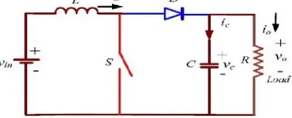
A DC - DC boost converter consists of an inductor, diode, MOSFET used as a switch, output filter capacitor and resistive load. When the switch is closed and supply voltage is given, inductor current increases. When the switch is opened, both inductor and supply voltage gets discharged through the load. Hence a higher voltage at the output is obtained than the given input voltage. Assumptions made are the components are ideal and lossless and converter is in continuous conduction mode. Fig.1 shows the boost converter.
Fig. 1 Boost Converter
When the main switch is ON,
When the switch is OFF,
(2)
Averaging the state equations over a switching cycle and introduce perturbation in state variables and take Laplace transforms, the control equations are obtained as,
Control to output transfer function
Control to input current transfer function
Current to output transfer function
Two control loops an inner current control loop (fast loop) and outer voltage control loop (slow loop) are used to regulate the output voltage. Setting the outer voltage loop bandwidth (BW) lower than the inner current loop makes the design of controller easier. The average input current should be controlled to be dc, which requires that bandwidths of voltage and current loops are separated with a slow voltage loop and a fast current loop. Fig.2 shows closed loop controlled boost converter with two controllers.
Fig.2 Closed Loop Controlled Boost Converter
B) CONTROLMETHOD
When converters are connected in parallel and if there is change in output power or load, this will cause mismatch in converter output voltage which will cause circulating current flows between the converters. Fig.3. shows the steady state equivalent circuit for the dc output side of two parallel connected dc-dc converters. In this figure, VDC1, VDC2, I1,
I2, and R1, R2represent output voltages, output currents, and cable resistances of converter-1 (Conv-1) and converter-2
(Conv-2), respectively. The output side of the converter can be represented as a voltage source in series with the cable resistance. If VDC1> VDC2, IC12is the circulating current component from Conv-1 to Conv-2 and I1’ the load component
Fig.3 Steady-state equivalent side of dc output side[1].
By applying Kirchoff's voltage law,
− − = 0 (6)
− − = 0 (7)
The circulating current can be expressed as,
= − = (8)
If R1 = R2, =
The virtual impedance method is used to implement Rdroop and the control diagram of parallel converter is shown in
Fig.4.This can be achieved by taking output currents feedback from Conv-1 and Conv-j, and multiplied with calculated Rdroop1 and Rdroopj, respectively. In parallel-connected system, the circulating current becomes zero if the current sharing
is proper. Simultaneously, insertion of the series resistor will cause the drop in the converter output voltage. Therefore, the proposed DI is taken as function of normalized current sharing difference and output power loss. The normalized power loss indirectly indicates the drop in the reference voltage. Calculation of minimum droop index is done by varying Rdroop and its maximum value will depend on the voltage regulation.
= min1
2[| − | + ] (9)
IV.SIMULATION RESULTS
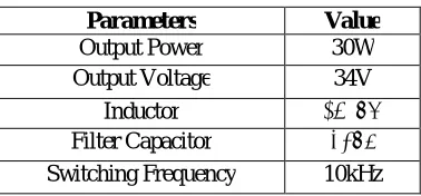
MATLAB/Simulink model of two parallel dc-dc boost converters with closed loop current and voltagecontrol are simulated. The output voltage should be maintained constantirrespective of load variations. The nominal parameters of boost converter are given in Table I.
TABLE I
NOMINAL PARAMETERS OF BOOST CONVERTER
Parameters Value
Output Power 30W
Output Voltage 34V
Inductor 481μH
Filter Capacitor 65μF
Switching Frequency 10kHz
A) Without any droop control method
Simulink model of parallel connected boost converters without any droop control is shown in Fig.5. The variation in the converter voltage is analysed, i.e. three cases both the converter output voltages are same,Converter 2 voltage is increased, Converter 2 voltage is decreased are analysed. The cable resistance of both the converters are assumed same.
Fig.5 Simulink model of parallel connected converters without any droop control
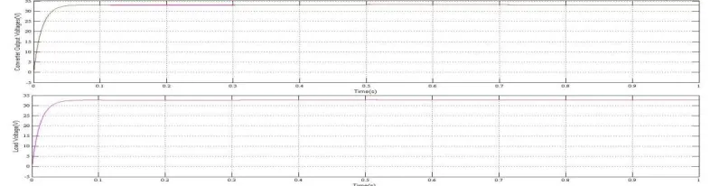
Fig.7 shows the load and converter voltages of parallel connected boost converter without any droop control. For the time 0-0.1s the converter 1 and converter 2 voltages are same. For the time 0.1-0.3s converter 1 voltage is greater than converter 2. Then again converter 1 and converter 2 output voltages are same for 0.3-0.5s and from 0.5-0.7s converter 2 output voltage is greater than converter 1.
Fig.7 Load and converter voltages of parallel connected boost converter without any droop control
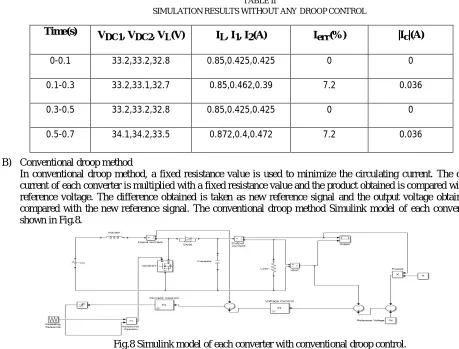
TABLE II
SIMULATION RESULTS WITHOUT ANY DROOP CONTROL
B) Conventional droop method
In conventional droop method, a fixed resistance value is used to minimize the circulating current. The output current of each converter is multiplied with a fixed resistance value and the product obtained is compared with the reference voltage. The difference obtained is taken as new reference signal and the output voltage obtained is compared with the new reference signal. The conventional droop method Simulink model of each converter is shown in Fig.8.
Fig.8 Simulink model of each converter with conventional droop control.
The load, converter currents and circulating current with conventional droop method are shown in Fig.9 and it shows that the circulating current is minimized into some extent. But in some cases, this method doesn't give better results.
Time(s) V
DC1, VDC2, VL(V) IL, I1, I2(A) Ierr(%) |Ic|(A)
0-0.1 33.2,33.2,32.8 0.85,0.425,0.425 0 0
0.1-0.3 33.2,33.1,32.7 0.85,0.462,0.39 7.2 0.036
0.3-0.5 33.2,33.2,32.8 0.85,0.425,0.425 0 0
Fig.9 Load, converter currents and circulating current of parallel connected boost converter with conventional droop control
Load and converter voltages are shown in Fig.10 and it is clear that compared to without any droop control method the voltage difference between the time 0.5-0.7s is smaller and therefore the circulating current during this period is minimized. The simulation results for different cases are given in Table III.
Fig.10 Load and converter voltages of parallel connected boost converter with conventional droop control
TABLE III
SIMULATION RESULTS WITH CONVENTIONAL DROOP CONTROL
Time(s) V
DC1, VDC2, VL(V) IL, I1, I2(A) Ierr(%) |Ic|(A)
0-0.1 33.2,33.2,32.8 0.85,0.425,0.425 0 0
0.1-0.3 33.2,33.1,32.7 0.85,0.459,0.386 7.2 0.036
0.3-0.5 33.2,33.2,32.8 0.85,0.425,0.425 0 0
0.5-0.7 33.1,33.2,32.75 0.85,0.421,0.43 0.9 0.0045
C) Adaptive Droop Control
In adaptive droop control method the virtual resistance value is calculated instantaneously by droop index calculation. The calculation of minimum DI is done by varying the droop resistance value and its maximum value will depend on the voltage regulation which means, the product of converter output current and Rdroop should not increase the
maximum allowable voltage deviation. If the rated voltage of dc grid is 34 ±5%V an each converter rated current is 0.44A, then the product of converter rated current and Rdroop should be less than the maximum deviation in the dc bus
Fig.11 Simulink model of parallel connected converters with adaptive droop control
The load, converter currents and circulating current are shown in Fig.12 and from the figure it is clear that the converter 1 and converter 2 are equally shared and the circulating current is negligible in all cases.
Fig.12 Load, converter currents and circulating current of parallel connected boost converter with adaptive droop control
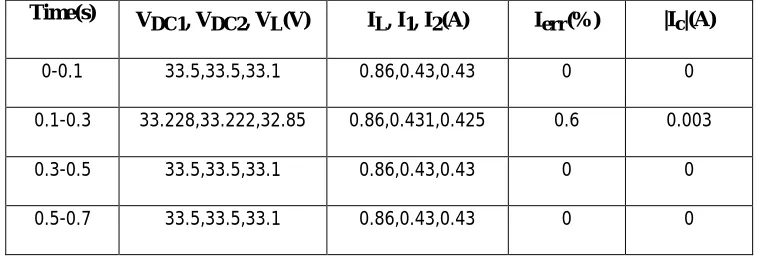
Load and converter voltages are shown in Fig.13 and both the converter voltages are equal in all cases.Table IV shows the simulation results of different cases with adaptive droop control strategy.
Fig.13 Load and converter voltages of parallel connected boost converter with adaptive droop control
TABLE IV
SIMULATION RESULTS WITH ADAPTIVEDROOP CONTROL
Time(s) V
DC1, VDC2, VL(V) IL, I1, I2(A) Ierr(%) |Ic|(A)
0-0.1 33.5,33.5,33.1 0.86,0.43,0.43 0 0
0.1-0.3 33.228,33.222,32.85 0.86,0.431,0.425 0.6 0.003
0.3-0.5 33.5,33.5,33.1 0.86,0.43,0.43 0 0
V.CONCLUSION
Adaptive droop control method calculates virtual resistance Rdrooppositive or negative values instantaneously based on
the converter output voltage mismatch. This improve the current sharing difference and decreases circulating current between the converters, in transient as well as in steady state condition and it improves the voltage regulation. The effects of converter cable resistances are taken into account to verify the performance of themethod. The dc-dc converter is controlled by closed loop controls which have an outer voltage loop and inner current control loop. The simulation results show that the circulating current is minimized and load is effectively shared with this decentralized method. This method is effectively implemented for the converters with different cable resistances and alsofor DGs having different ratings.
REFERENCES
[1] S. Augustine, M K. Mishra, N. Lakshminarasamma, “Adaptive Droop Control Strategy for Load Sharing and Circulating Current Minimization in Low-Voltage Standalone DC Microgrid", IEEE Transaction on Sustainable Energy, Vol. 6, pp. 132-141, January 2015. [2] Rodrigo A F, Ferreira1, Henrique A.C. Braga1, Andre A Ferreira1, Pedro G. Barbosa1, “ Analysis of Voltage Droop Control Method for dc
Microgrids with Simulink: Modelling and Simulation ", IEEE Transaction on Industrial Electronics, Vol. 60, no. 1, pp. 98-111, January 2013. [3] J. Guerrero, J. Vasquez, J. Matas, L. de Vicua, M. Castilla, “ Hierarchical control of droop-controlled ac and dc microgrids: A general
approach toward -standardization", IEEE Transaction on Industrial Electronics, Vol. 58 , no. 1, pp.158-172 , January 2011.
[4] J. Rajagopalan, K. Xing, Y. Guo, F. Lee, and B. Manners, “Modelling and dynamic analysis of paralleled dc/dc converters with master-slave current sharing control,” in Proc. IEEE 11th Annual APEC Conference, Vol.2, pp. 678-684, March 1996.
[5] J.-W. Kim, H.-S. Choi, and B. H. Cho, “ A novel droop method for converter parallel operation", IEEE Transaction on Power Electronics, Vol. 17, no. 1, pp. 25-32,January 2002.
[6] S. Luo, Z. Ye, R.-L. Lin, and F. Lee, “A classification and evaluation of paralleling methods for power supply modules", In Proceedings IEEE 30th Annual PESC Conference, Vol. 2, pp. 901-908, January 1999.
[7] B. Choi, “ Comparative study on paralleling schemes of converter modules for distributed power applications", IEEE Transaction on Industrial Electronics, Vol. 45, no. 2, pp. 194-199, April 1998.
[8] Konstantinos F. Krommydas, Antonio T. Alexandridis, “Design and Passivity-Based Stability Analysis of a PI Current-Mode Controller for dc/dc Boost Converters ", American Control Conference, Portland, USA, 2014.
[9] Evandro de C. Gomes, Ginalber L. O. Serra1, Jos Gomes de Matos, “ A Fuzzy PI Controller Application in Boost Converter", Electronics, Robotics and Automotive Mechanics Conference, March 2011.
[10] M. Elshaer, A. Mohammed O. Mohammed, “Smart Optimal Control of DC-DC Boost Converter in PV Systems", IEEE/PES Transmission and Distribution Conference and Exposition, Latin America, September 2010.